2007 TOYOTA SIENNA stop start
[x] Cancel search: stop startPage 1392 of 3000

U151E AUTOMATIC TRANSAXLE – AUTOMATIC TRANSAXLE SYSTEMAX–15
AX
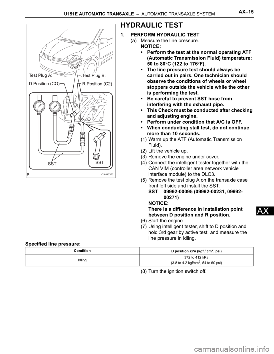
HYDRAULIC TEST
1. PERFORM HYDRAULIC TEST
(a) Measure the line pressure.
NOTICE:
• Perform the test at the normal operating ATF
(Automatic Transmission Fluid) temperature:
50 to 80
C (122 to 176F).
• The line pressure test should always be
carried out in pairs. One technician should
observe the conditions of wheels or wheel
stoppers outside the vehicle while the other
is performing the test.
• Be careful to prevent SST hose from
interfering with the exhaust pipe.
• This Check must be conducted after checking
and adjusting engine.
• Perform under condition that A/C is OFF.
• When conducting stall test, do not continue
more than 10 seconds.
(1) Warm up the ATF (Automatic Transmission
Fluid).
(2) Lift the vehicle up.
(3) Remove the engine under cover.
(4) Connect the intelligent tester together with the
CAN VIM (controller area network vehicle
interface module) to the DLC3.
(5) Remove the test plug A on the transaxle case
front left side and install the SST.
SST 09992-00095 (09992-00231, 09992-
00271)
NOTICE:
There is a difference in installation point
between D position and R position.
(6) Start the engine.
(7) Using intelligent tester, shift to D position and
hold 3rd gear by active test, and measure the
line pressure in idling.
Specified line pressure:
(8) Turn the ignition switch off.
C160153E01
Condition
D position kPa (kgf / cm2, psi)
Idling372 to 412 kPa
(3.8 to 4.2 kgf/cm
2, 54 to 60 psi)
Page 1399 of 3000

AX–22U151E AUTOMATIC TRANSAXLE – AUTOMATIC TRANSAXLE SYSTEM
AX
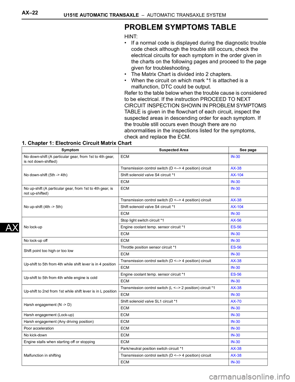
PROBLEM SYMPTOMS TABLE
HINT:
• If a normal code is displayed during the diagnostic trouble
code check although the trouble still occurs, check the
electrical circuits for each symptom in the order given in
the charts on the following pages and proceed to the page
given for troubleshooting.
• The Matrix Chart is divided into 2 chapters.
• When the circuit on which mark *1 is attached is a
malfunction, DTC could be output.
Refer to the table below when the trouble cause is considered
to be electrical. If the instruction PROCEED TO NEXT
CIRCUIT INSPECTION SHOWN IN PROBLEM SYMPTOMS
TABLE is given in the flowchart of each circuit, inspect the
suspected areas in descending order for each symptom. If
the trouble still occurs even though there are no
abnormalities in the inspections listed for the symptoms,
check and replace the ECM.
1. Chapter 1: Electronic Circuit Matrix Chart
Symptom Suspected Area See page
No down-shift (A particular gear, from 1st to 4th gear,
is not down-shifted)ECMIN-30
No down-shift (5th -> 4th)Transmission control switch (D <--> 4 position) circuitAX-38
Shift solenoid valve S4 circuit *1AX-104
ECMIN-30
No up-shift (A particular gear, from 1st to 4th gear, is
not up-shifted)ECMIN-30
No up-shift (4th -> 5th)Transmission control switch (D <--> 4 position) circuitAX-38
Shift solenoid valve S4 circuit *1AX-104
ECMIN-30
No lock-upStop light switch circuit *1AX-56
Engine coolant temp. sensor circuit *1ES-56
ECMIN-30
No lock-up off ECMIN-30
Shift point too high or too lowThrottle position sensor circuit *1ES-56
ECMIN-30
Up-shift to 5th from 4th while shift lever is in 4 positionTransmission control switch (D <--> 4 position) circuitAX-38
ECMIN-30
Up-shift to 5th from 4th while engine is coldEngine coolant temp. sensor circuit *1ES-56
ECMIN-30
Up-shift to 2nd from 1st while shift lever is in L positionTransmission control switch (L <--> 2 position) circuit *1AX-38
ECMIN-30
Harsh engagement (N -> D)Shift solenoid valve SL1 circuit *1AX-70
ECMIN-30
Harsh engagement (Lock-up) ECMIN-30
Harsh engagement (Any driving position) ECMIN-30
Poor acceleration ECMIN-30
No kick-down ECMIN-30
Engine stalls when starting off or stopping ECMIN-30
Malfunction in shiftingPark/neutral position switch circuit *1AX-38
Transmission control switch (D <--> 4 position) circuitAX-38
ECMIN-30
Page 1401 of 3000

AX–24U151E AUTOMATIC TRANSAXLE – AUTOMATIC TRANSAXLE SYSTEM
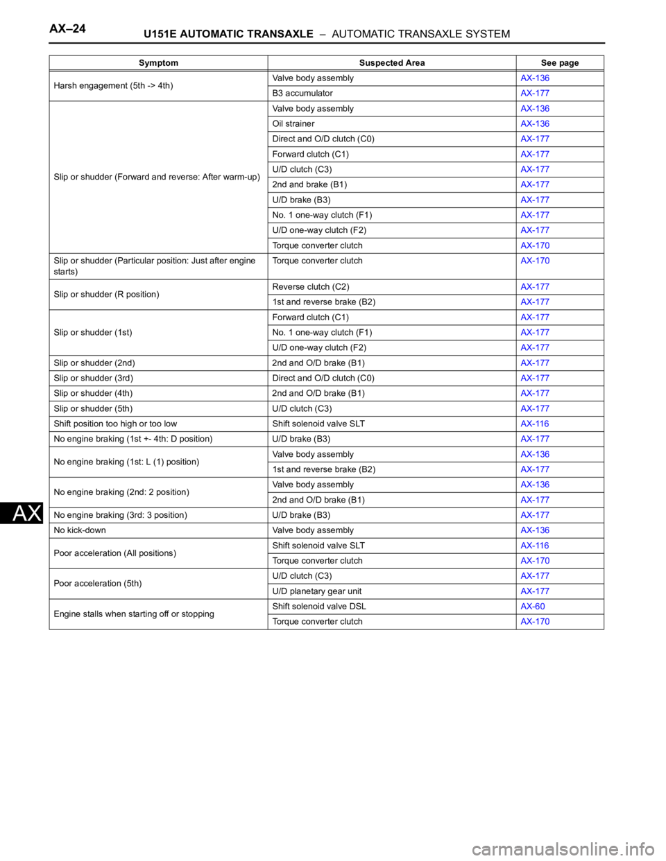
AX
Harsh engagement (5th -> 4th)Valve body assemblyAX-136
B3 accumulatorAX-177
Slip or shudder (Forward and reverse: After warm-up)Valve body assemblyAX-136
Oil strainerAX-136
Direct and O/D clutch (C0)AX-177
Forward clutch (C1)AX-177
U/D clutch (C3)AX-177
2nd and brake (B1)AX-177
U/D brake (B3)AX-177
No. 1 one-way clutch (F1)AX-177
U/D one-way clutch (F2)AX-177
Torque converter clutchAX-170
Slip or shudder (Particular position: Just after engine
starts)Torque converter clutchAX-170
Slip or shudder (R position)Reverse clutch (C2)AX-177
1st and reverse brake (B2)AX-177
Slip or shudder (1st)Forward clutch (C1)AX-177
No. 1 one-way clutch (F1)AX-177
U/D one-way clutch (F2)AX-177
Slip or shudder (2nd) 2nd and O/D brake (B1)AX-177
Slip or shudder (3rd) Direct and O/D clutch (C0)AX-177
Slip or shudder (4th) 2nd and O/D brake (B1)AX-177
Slip or shudder (5th) U/D clutch (C3)AX-177
Shift position too high or too low Shift solenoid valve SLTAX-116
No engine braking (1st +- 4th: D position) U/D brake (B3)AX-177
No engine braking (1st: L (1) position)Valve body assemblyAX-136
1st and reverse brake (B2)AX-177
No engine braking (2nd: 2 position)Valve body assemblyAX-136
2nd and O/D brake (B1)AX-177
No engine braking (3rd: 3 position) U/D brake (B3)AX-177
No kick-down Valve body assemblyAX-136
Poor acceleration (All positions)Shift solenoid valve SLTAX-116
Torque converter clutchAX-170
Poor acceleration (5th)U/D clutch (C3)AX-177
U/D planetary gear unitAX-177
Engine stalls when starting off or stoppingShift solenoid valve DSLAX-60
Torque converter clutchAX-170 Symptom Suspected Area See page
Page 1406 of 3000

AX–36U151E AUTOMATIC TRANSAXLE – AUTOMATIC TRANSAXLE SYSTEM
AX
FAIL-SAFE CHART
1. FAIL-SAFE
This function minimizes the loss of the ECT functions
when any malfunction occurs in a sensor or solenoid.
(a) ATF (Automatic Transmission Fluid) temperature
sensor:
When the ATF temperature sensor has a
malfunction, 5th upshift is prohibited.
(b) Counter gear speed sensor NC (Speed sensor NC):
When the counter gear speed sensor has a
malfunction, 5th upshift is prohibited.
(c) Shift solenoid valve DSL:
When the solenoid valve DSL has a malfunction, the
current to the solenoid valve is stopped.
This stops lock-up control, then fuel economy
decreases.
(d) Shift solenoid valve SL1, SL2, SL3 and S4:
Fail safe function:
If either of the shift solenoid valve circuits develops
an open or short, the ECM turns the other shift
solenoid "ON" and "OFF" in order to shift into the
gear positions shown in the table below.
Manual shifting as shown in the following table must
be done (In case of a short circuit, the ECM stops
sending the current to the short circuited solenoid).
Even if starting the engine in the fail-safe mode, the
gear position remains in the same position.
HINT:
FL: Flex Lock-up
NormalSolenoid ValveSL1 ON OFF ON OFF OFF
SL2 ON ON OFF FL FL
SL3 OFF OFF OFF ON ON
S4 OFF OFF OFF OFF ON
Gear Position 1st 2nd 3rd 4th 5th
SL1
Malfunction
(During driving
at 1st or 2nd)Solenoid ValveSL1 OFF
SL2 ON ON OFF to ON FL to ON FL to ON
SL3 OFF OFF OFF ON to OFF ON to OFF
S4 OFF OFF OFF OFF ON to OFF
Gear Position 1st to 2nd 2nd 3rd to 2nd 4th to 2nd 5th to 2nd
SL1
Malfunction
(During driving
at 3rd)Solenoid ValveSL1 OFF
SL2 ON to FL ON to FL OFF to FL FL FL
SL3 OFF OFF OFF ON to OFF ON to OFF
S4 OFF to ON OFF to ON OFF to ON OFF to ON ON
Gear Position 1st to 4th 2nd to 4th 3rd to 4th 4th 5th to 4th
SL1
Malfunction
(During driving
at 4th or 5th)Solenoid ValveSL1 OFF
SL2 ON to FL ON to FL OFF to FL FL FL
SL3 OFF to ON OFF to ON OFF to ON ON ON
S4 OFF OFF OFF OFF ON
Gear Position 1st to 4th 2nd to 4th 3rd to 4th 4th 5th to 4th
Page 1460 of 3000

AX–94U151E AUTOMATIC TRANSAXLE – AUTOMATIC TRANSAXLE SYSTEM
AX
DESCRIPTION
Shifting from 1st to 5th is performed in combination with "ON" and "OFF" operation of the shift solenoid
valves SL1, SL2, SL3, S4 and SR which are controlled by the ECM. If an open or short circuit occurs in
either of the shift solenoid valves, the ECM controls the remaining normal shift solenoid valves to allow
the vehicle to be operated smoothly (Fail safe function).
MONITOR DESCRIPTION
The ECM commands gear shifts by turning the shift solenoid valves "ON/OFF". When there is an open or
short circuit in any shift solenoid valve circuit, the ECM detects the problem and illuminates the MIL and
stores the DTC. And the ECM performs the fail-safe function and turns the other normal shift solenoid
valves "ON/OFF" (In case of an open or short circuit, the ECM stops sending current to the circuit.)
(See page AX-30).
MONITOR STRATEGY
TYPICAL ENABLING CONDITIONS
TYPICAL MALFUNCTION THRESHOLDS
COMPONENT OPERATING RANGE
DTC P0778Pressure Control Solenoid "B" Electrical (Shift
Solenoid Valve SL2)
DTC No. DTC Detection Condition Trouble Area
P0778ECM checks for an open or short circuit in shift solenoid
valves SL2 (1-trip detection logic)
Hybrid IC for solenoid indicates fail.• Open or short in shift solenoid valve SL2 circuit
• Shift solenoid valve SL2
•ECM
Related DTCs P0778: Shift solenoid valve SL2/Range check
Required sensors/Components Shift solenoid valve SL2
Frequency of operation Continuous
Duration 1 sec.
MIL operation Immediate
Sequence of operation None
The monitor will run whenever this DTC is not present. None
Solenoid current cut status Not cut
Battery voltage11 V or more
Ignition switchON
StarterOFF
CPU commanded duty ratio to SL2 19% or more
Solenoid status from IC Fail (Open or short)
Output signal dutyLess than 100%
Page 1480 of 3000

AX–114U151E AUTOMATIC TRANSAXLE – AUTOMATIC TRANSAXLE SYSTEM
AX
DESCRIPTION
Shifting from 1st to 5th is performed in combination with "ON" and "OFF" operation of the shift solenoid
valves SL1, SL2, SL3, S4 and SR which are controlled by the ECM. If an open or short circuit occurs in
either of the shift solenoid valves, the ECM controls the remaining normal shift solenoid valves to allow
the vehicle to be operated smoothly (Fail safe function).
MONITOR DESCRIPTION
The ECM commands gear shifts by turning the shift solenoid valves "ON/OFF". When there is an open or
short circuit in any shift solenoid valve circuit, the ECM detects the problem and illuminates the MIL and
stores the DTC. And the ECM performs the fail-safe function and turns the other normal shift solenoid
valves "ON/OFF" (In case of an open or short circuit, the ECM stops sending current to the circuit.)
(See page AX-30).
MONITOR STRATEGY
TYPICAL ENABLING CONDITIONS
P0985: Range check (Low resistance):
P0986: Range check (High resistance):
DTC P0985Shift Solenoid "E" Control Circuit Low (Shift
Solenoid Valve SR)
DTC P0986Shift Solenoid "E" Control Circuit High (Shift
Solenoid Valve SR)
DTC No. DTC Detection Condition Trouble Area
P0985ECM detects short in solenoid valve SR circuit 2 times
when solenoid valve SR is operated (1-trip detection
logic)• Short in shift solenoid valve SR circuit
• Shift solenoid valve SR
•ECM
P0986ECM detects open in solenoid valve SR circuit 2 times
when solenoid valve SR is not operated (1-trip
detection logic)• Open in shift solenoid valve SR circuit
• Shift solenoid valve SR
•ECM
Related DTCsP0985: Shift solenoid valve SR/Range check (Low resistance)
P0986: Shift solenoid valve SR/Range check (High resistance)
Required sensors/Components Shift solenoid valve SR
Frequency of operation Continuous
Duration 0.064 sec.
MIL operation Immediate
Sequence of operation None
The monitor will run whenever this DTC is not present. None
Shift solenoid valve SRON
Battery voltage8 V or more
Ignition switchON
StarterOFF
The monitor will run whenever this DTC is not present. None
Shift solenoid valve SROFF
Battery voltage8 V or more
Ignition switchON
StarterOFF
Page 1500 of 3000

U151E AUTOMATIC TRANSAXLE – AUTOMATIC TRANSAXLE SYSTEMAX–13
AX
MECHANICAL SYSTEM TESTS
1. PERFORM MECHANICAL SYSTEM TESTS
(a) Measure the stall speed.
The object of this test is to check the overall
performance of the transaxle and engine by
measuring the stall speeds in the D position.
NOTICE:
• Driving test should be done on a paved road
(a nonskid road).
• Perform the test at the normal operating ATF
(Automatic Transmission Fluid) temperature
50 to 80
C (122 to 176F).
• Do not continuously run this test for longer
than 10 seconds.
• To ensure safety, do this test in a wide, clear
level area which provides good traction.
• The stall test should always be carried out in
pairs. One technician should observe the
conditions of wheels or wheel stoppers
outside the vehicle while the other is doing
the test.
(1) Chock the 4 wheels.
(2) Connect the intelligent tester together with the
CAN VIM (controller area network vehicle
interface module) to the DLC3.
(3) Fully apply the parking brake.
(4) Keep your left foot pressed firmly on the brake
pedal.
(5) Start the engine.
(6) Shift into the D position. Press all the way down
on the accelerator pedal with your right foot.
(7) Quickly read the stall speed at this time.
Stall speed:
2,300 +- 150 rpm
Evaluation:
Problem Possible cause
(a) Stall engine speed is low in D position• Engine power output may be insufficient
• Stator one-way clutch not operating properly
HINT:
If the value is less than the specified value by 600 rpm or more, the
torque converter could be faulty.
(b) Stall engine speed is high in D position• Line pressure is too low
• Forward clutch slipping
• U/D (Underdrive) brake slipping
• U/D (Underdrive) one-way clutch is not operating properly
• No.1 one-way clutch not operating properly
• Improper fluid level
Page 1501 of 3000

AX–14U151E AUTOMATIC TRANSAXLE – AUTOMATIC TRANSAXLE SYSTEM
AX
(b) Measure the time lag.
(1) When the shift lever is shifted while the engine is
idling, there will be a certain time lapse or lag
before the shock can be felt. This is used for
checking the condition of the clutch and brake.
NOTICE:
• Perform the test at the normal operating
ATF (Automatic Transmission Fluid)
temperature: 50 to 80
C (122 to 176F).
• Be sure to allow 1 minute interval between
tests.
• Perform the test three times, and measure
the time lags. Calculate the average value
of the three time lags.
• When conducting stall test, do not
continue more than 10 seconds.
(2) Connect the intelligent tester together with the
CAN VIM (controller area network vehicle
interface module) to the DLC3.
(3) Fully apply the parking brake.
(4) Start and warm up the engine and check idle
speed.
Idle speed:
approx. 700 rpm (In N position and A/C
OFF)
(5) Shift the lever from N to D position. Using a stop
watch, measure the time from when the lever is
shifted until the shock is felt.
Time lag:
N
D less than 1.2 seconds
(6) In the same way, measure the time lag for N
R.
Time lag:
N
R less than 1.5 seconds
Evaluation (If N
D or N R time lag is longer than the specified):
Problem Possible cause
N
D time lag is longer• Line pressure is too low
• Forward clutch worn
• No.1 one-way clutch is not operating properly
• U/D (Underdrive) one-way clutch is not operating
• U/D (Underdrive) brake worn
N
R time lag is longer• Line pressure is too low
• Reverse clutch worn
• 1st and reverse brake worn
• U/D (Underdrive) brake worn