2007 TOYOTA SIENNA stop start
[x] Cancel search: stop startPage 832 of 3000
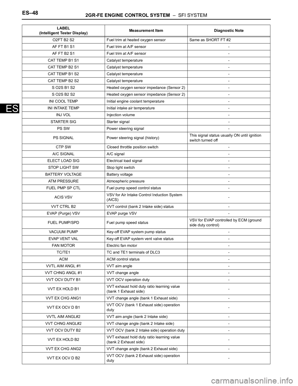
ES–482GR-FE ENGINE CONTROL SYSTEM – SFI SYSTEM
ES
O2FT B2 S2 Fuel trim at heated oxygen sensor Same as SHORT FT #2
AF FT B1 S1 Fuel trim at A/F sensor -
AF FT B2 S1 Fuel trim at A/F sensor -
CAT TEMP B1 S1 Catalyst temperature -
CAT TEMP B2 S1 Catalyst temperature -
CAT TEMP B1 S2 Catalyst temperature -
CAT TEMP B2 S2 Catalyst temperature -
S O2S B1 S2 Heated oxygen sensor impedance (Sensor 2) -
S O2S B2 S2 Heated oxygen sensor impedance (Sensor 2) -
INI COOL TEMP Initial engine coolant temperature -
INI INTAKE TEMP Initial intake air temperature -
INJ VOL Injection volume -
STARTER SIG Starter signal -
PS SW Power steering signal -
PS SIGNAL Power steering signal (history)This signal status usually ON until ignition
switch turned off
CTP SW Closed throttle position switch -
A/C SIGNAL A/C signal -
ELECT LOAD SIG Electrical load signal -
STOP LIGHT SW Stop light switch -
BATTERY VOLTAGE Battery voltage -
ATM PRESSURE Atmospheric pressure -
FUEL PMP SP CTL Fuel pump speed control status -
ACIS VSVVSV for Air Intake Control Induction System
(AICS)-
VVT CTRL B2 VVT control (bank 2 Intake side) status -
EVAP (Purge) VSV EVAP purge VSV -
FUEL PUMP/SPD Fuel pump speed statusVSV for EVAP controlled by ECM (ground
side duty control)
VACUUM PUMP Key-off EVAP system pump status -
EVAP VENT VAL Key-off EVAP system vent valve status -
FAN MOTOR Electric fan motor -
TC/TE1 TC and TE1 terminals of DLC3 -
ACM ACM control status -
VVTL AIM ANGL #1 VVT aim angle -
VVT CHNG ANGL #1 VVT change angle -
VVT OCV DUTY B1 VVT OCV operation duty -
VVT EX HOLD B1VVT exhaust hold duty ratio learning value
(bank 1 Exhaust side)-
VVT EX CHG ANG1 VVT change angle (bank 1 Exhaust side) -
VVT EX OCV D B1VVT OCV (bank 1 Exhaust side) operation
duty-
VVTL AIM ANGL#2 VVT aim angle (bank 2 Intake side) -
VVT CHNG ANGL#2 VVT change angle (bank 2 Intake side) -
VVT OCV DUTY B2 VVT OCV (bank 2 Intake side) operation duty -
VVT EX HOLD B2VVT exhaust hold duty ratio learning value
(bank 2 Exhaust side)-
VVT EX CHG ANG2 VVT change angle (bank 2 Exhaust side) -
VVT EX OCV D B2VVT OCV (bank 2 Exhaust side) operation
duty- LABEL
(Intelligent Tester Display)Measurement Item Diagnostic Note
Page 1118 of 3000
FU–82GR-FE FUEL – FUEL SYSTEM
FU
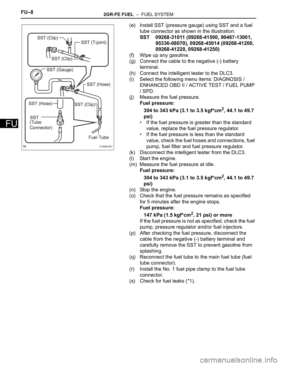
(e) Install SST (pressure gauge) using SST and a fuel
tube connector as shown in the illustration.
SST 09268-31011 (09268-41500, 90467-13001,
95336-08070), 09268-45014 (09268-41200,
09268-41220, 09268-41250)
(f) Wipe up any gasoline.
(g) Connect the cable to the negative (-) battery
terminal.
(h) Connect the intelligent tester to the DLC3.
(i) Select the following menu items: DIAGNOSIS /
ENHANCED OBD II / ACTIVE TEST / FUEL PUMP
/ SPD.
(j) Measure the fuel pressure.
Fuel pressure:
304 to 343 kPa (3.1 to 3.5 kgf*cm
2, 44.1 to 49.7
psi)
• If the fuel pressure is greater than the standard
value, replace the fuel pressure regulator.
• If the fuel pressure is less than the standard
value, check the fuel hoses and connections, fuel
pump, fuel filter and fuel pressure regulator.
(k) Disconnect the intelligent tester from the DLC3.
(l) Start the engine.
(m) Measure the fuel pressure at idle.
Fuel pressure:
304 to 343 kPa (3.1 to 3.5 kgf*cm
2, 44.1 to 49.7
psi)
(n) Stop the engine.
(o) Check that the fuel pressure remains as specified
for 5 minutes after the engine stops.
Fuel pressure:
147 kPa (1.5 kgf*cm
2, 21 psi) or more
If the fuel pressure is not as specified, check the fuel
pump, pressure regulator and/or fuel injectors.
(p) After checking the fuel pressure, disconnect the
cable from the negative (-) battery terminal and
carefully remove the SST to prevent gasoline from
splashing.
(q) Reconnect the fuel tube to the main fuel tube (fuel
tube connector).
(r) Install the No. 1 fuel pipe clamp to the fuel tube
connector.
(s) Check for fuel leaks (*1).
A129461E01
Page 1122 of 3000
2GR-FE FUEL – FUEL SYSTEMFU–1
FU
FUEL SYSTEM
PRECAUTION
1. PRECAUTION
(a) Before inspecting and repairing the fuel system,
disconnect the cable from the negative (-) battery
terminal.
(b) Do not smoke or work near fire when handling the
fuel system.
(c) Keep gasoline away from rubber or leather parts.
2. DISCHARGE FUEL SYSTEM PRESSURE (*1)
CAUTION:
• Perform the following procedures to prevent fuel
from spilling out before removing any fuel system
parts.
• Pressure will still remain in the fuel line even after
performing the following procedures. When
disconnecting the fuel line, cover it with a shop
rag or a piece of cloth to prevent fuel from
spraying or coming out.
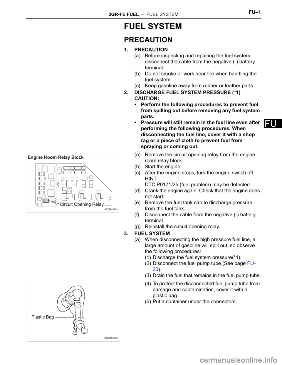
(a) Remove the circuit opening relay from the engine
room relay block.
(b) Start the engine.
(c) After the engine stops, turn the engine switch off.
HINT:
DTC P0171/25 (fuel problem) may be detected.
(d) Crank the engine again. Check that the engine does
not start.
(e) Remove the fuel tank cap to discharge pressure
from the fuel tank.
(f) Disconnect the cable from the negative (-) battery
terminal.
(g) Reinstall the circuit opening relay.
3. FUEL SYSTEM
(a) When disconnecting the high pressure fuel line, a
large amount of gasoline will spill out, so observe
the following procedures:
(1) Discharge the fuel system pressure(*1).
(2) Disconnect the fuel pump tube (See page FU-
30).
(3) Drain the fuel that remains in the fuel pump tube.
(4) To protect the disconnected fuel pump tube from
damage and contamination, cover it with a
plastic bag.
(5) Put a container under the connectors.
A075349E01
B000679E07
Page 1127 of 3000
FU–82GR-FE FUEL – FUEL SYSTEM
FU
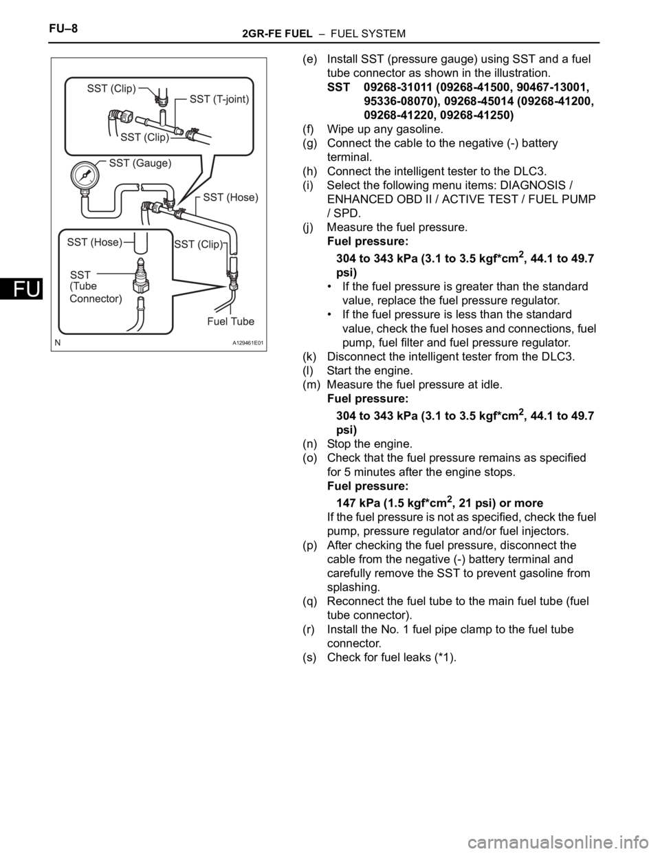
(e) Install SST (pressure gauge) using SST and a fuel
tube connector as shown in the illustration.
SST 09268-31011 (09268-41500, 90467-13001,
95336-08070), 09268-45014 (09268-41200,
09268-41220, 09268-41250)
(f) Wipe up any gasoline.
(g) Connect the cable to the negative (-) battery
terminal.
(h) Connect the intelligent tester to the DLC3.
(i) Select the following menu items: DIAGNOSIS /
ENHANCED OBD II / ACTIVE TEST / FUEL PUMP
/ SPD.
(j) Measure the fuel pressure.
Fuel pressure:
304 to 343 kPa (3.1 to 3.5 kgf*cm
2, 44.1 to 49.7
psi)
• If the fuel pressure is greater than the standard
value, replace the fuel pressure regulator.
• If the fuel pressure is less than the standard
value, check the fuel hoses and connections, fuel
pump, fuel filter and fuel pressure regulator.
(k) Disconnect the intelligent tester from the DLC3.
(l) Start the engine.
(m) Measure the fuel pressure at idle.
Fuel pressure:
304 to 343 kPa (3.1 to 3.5 kgf*cm
2, 44.1 to 49.7
psi)
(n) Stop the engine.
(o) Check that the fuel pressure remains as specified
for 5 minutes after the engine stops.
Fuel pressure:
147 kPa (1.5 kgf*cm
2, 21 psi) or more
If the fuel pressure is not as specified, check the fuel
pump, pressure regulator and/or fuel injectors.
(p) After checking the fuel pressure, disconnect the
cable from the negative (-) battery terminal and
carefully remove the SST to prevent gasoline from
splashing.
(q) Reconnect the fuel tube to the main fuel tube (fuel
tube connector).
(r) Install the No. 1 fuel pipe clamp to the fuel tube
connector.
(s) Check for fuel leaks (*1).
A129461E01
Page 1242 of 3000
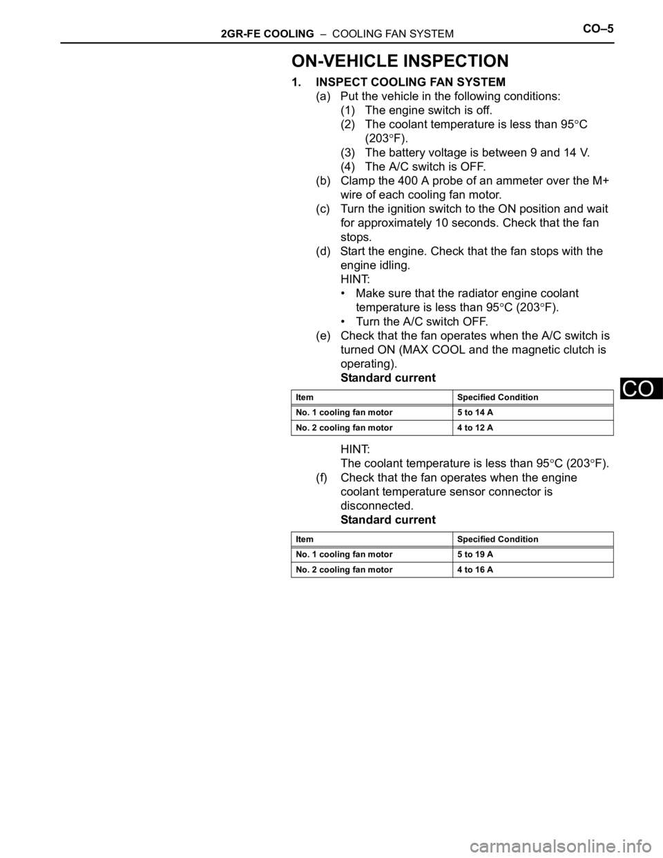
2GR-FE COOLING – COOLING FAN SYSTEMCO–5
CO
ON-VEHICLE INSPECTION
1. INSPECT COOLING FAN SYSTEM
(a) Put the vehicle in the following conditions:
(1) The engine switch is off.
(2) The coolant temperature is less than 95
C
(203
F).
(3) The battery voltage is between 9 and 14 V.
(4) The A/C switch is OFF.
(b) Clamp the 400 A probe of an ammeter over the M+
wire of each cooling fan motor.
(c) Turn the ignition switch to the ON position and wait
for approximately 10 seconds. Check that the fan
stops.
(d) Start the engine. Check that the fan stops with the
engine idling.
HINT:
• Make sure that the radiator engine coolant
temperature is less than 95
C (203F).
• Turn the A/C switch OFF.
(e) Check that the fan operates when the A/C switch is
turned ON (MAX COOL and the magnetic clutch is
operating).
Standard current
HINT:
The coolant temperature is less than 95
C (203F).
(f) Check that the fan operates when the engine
coolant temperature sensor connector is
disconnected.
Standard current
Item Specified Condition
No. 1 cooling fan motor 5 to 14 A
No. 2 cooling fan motor 4 to 12 A
Item Specified Condition
No. 1 cooling fan motor 5 to 19 A
No. 2 cooling fan motor 4 to 16 A
Page 1254 of 3000
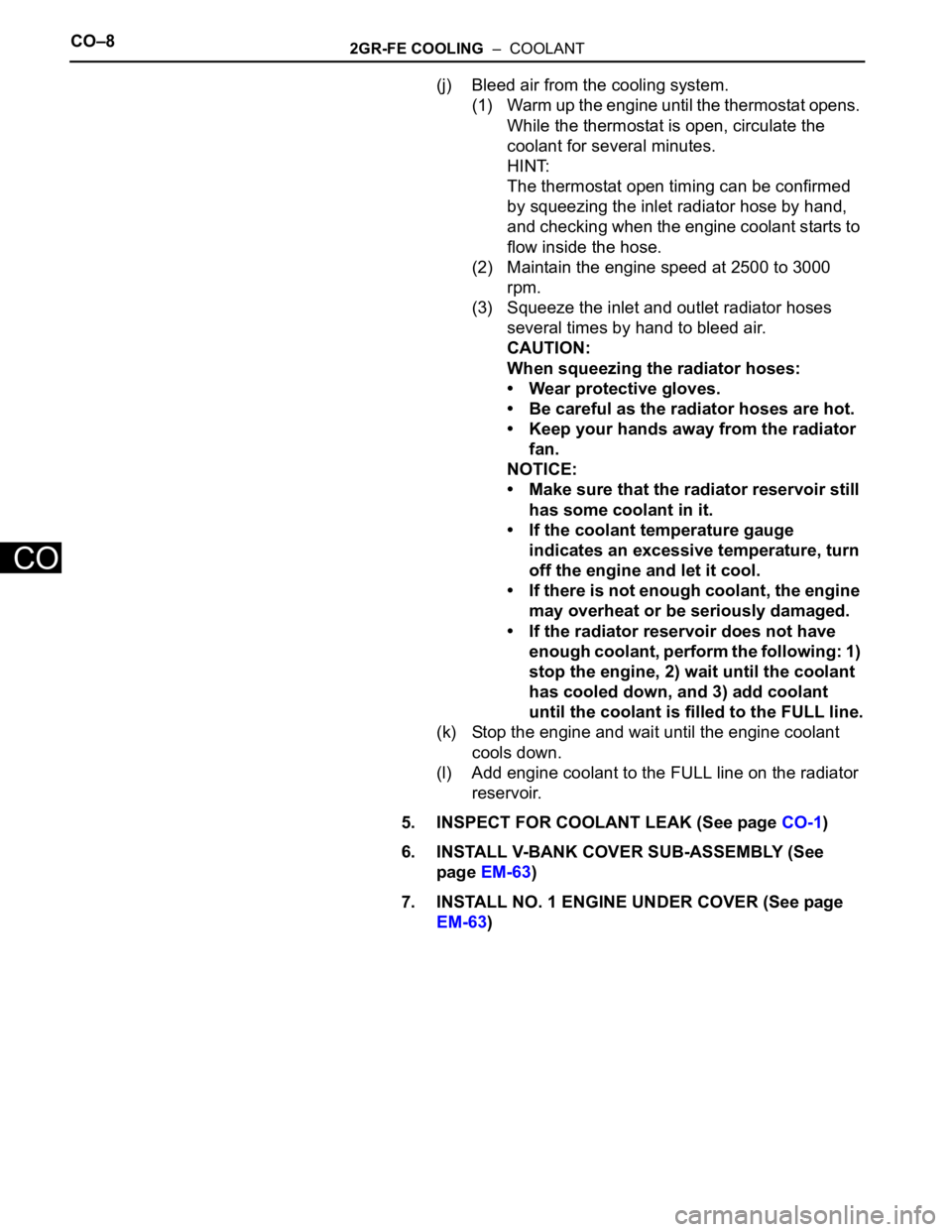
CO–82GR-FE COOLING – COOLANT
CO
(j) Bleed air from the cooling system.
(1) Warm up the engine until the thermostat opens.
While the thermostat is open, circulate the
coolant for several minutes.
HINT:
The thermostat open timing can be confirmed
by squeezing the inlet radiator hose by hand,
and checking when the engine coolant starts to
flow inside the hose.
(2) Maintain the engine speed at 2500 to 3000
rpm.
(3) Squeeze the inlet and outlet radiator hoses
several times by hand to bleed air.
CAUTION:
When squeezing the radiator hoses:
• Wear protective gloves.
• Be careful as the radiator hoses are hot.
• Keep your hands away from the radiator
fan.
NOTICE:
• Make sure that the radiator reservoir still
has some coolant in it.
• If the coolant temperature gauge
indicates an excessive temperature, turn
off the engine and let it cool.
• If there is not enough coolant, the engine
may overheat or be seriously damaged.
• If the radiator reservoir does not have
enough coolant, perform the following: 1)
stop the engine, 2) wait until the coolant
has cooled down, and 3) add coolant
until the coolant is filled to the FULL line.
(k) Stop the engine and wait until the engine coolant
cools down.
(l) Add engine coolant to the FULL line on the radiator
reservoir.
5. INSPECT FOR COOLANT LEAK (See page CO-1)
6. INSTALL V-BANK COVER SUB-ASSEMBLY (See
page EM-63)
7. INSTALL NO. 1 ENGINE UNDER COVER (See page
EM-63)
Page 1390 of 3000
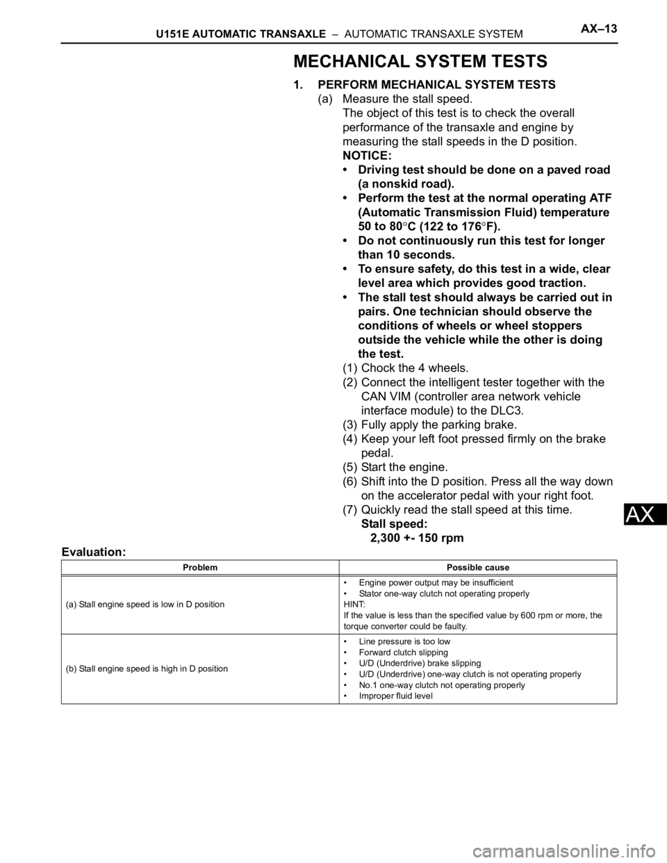
U151E AUTOMATIC TRANSAXLE – AUTOMATIC TRANSAXLE SYSTEMAX–13
AX
MECHANICAL SYSTEM TESTS
1. PERFORM MECHANICAL SYSTEM TESTS
(a) Measure the stall speed.
The object of this test is to check the overall
performance of the transaxle and engine by
measuring the stall speeds in the D position.
NOTICE:
• Driving test should be done on a paved road
(a nonskid road).
• Perform the test at the normal operating ATF
(Automatic Transmission Fluid) temperature
50 to 80
C (122 to 176F).
• Do not continuously run this test for longer
than 10 seconds.
• To ensure safety, do this test in a wide, clear
level area which provides good traction.
• The stall test should always be carried out in
pairs. One technician should observe the
conditions of wheels or wheel stoppers
outside the vehicle while the other is doing
the test.
(1) Chock the 4 wheels.
(2) Connect the intelligent tester together with the
CAN VIM (controller area network vehicle
interface module) to the DLC3.
(3) Fully apply the parking brake.
(4) Keep your left foot pressed firmly on the brake
pedal.
(5) Start the engine.
(6) Shift into the D position. Press all the way down
on the accelerator pedal with your right foot.
(7) Quickly read the stall speed at this time.
Stall speed:
2,300 +- 150 rpm
Evaluation:
Problem Possible cause
(a) Stall engine speed is low in D position• Engine power output may be insufficient
• Stator one-way clutch not operating properly
HINT:
If the value is less than the specified value by 600 rpm or more, the
torque converter could be faulty.
(b) Stall engine speed is high in D position• Line pressure is too low
• Forward clutch slipping
• U/D (Underdrive) brake slipping
• U/D (Underdrive) one-way clutch is not operating properly
• No.1 one-way clutch not operating properly
• Improper fluid level
Page 1391 of 3000
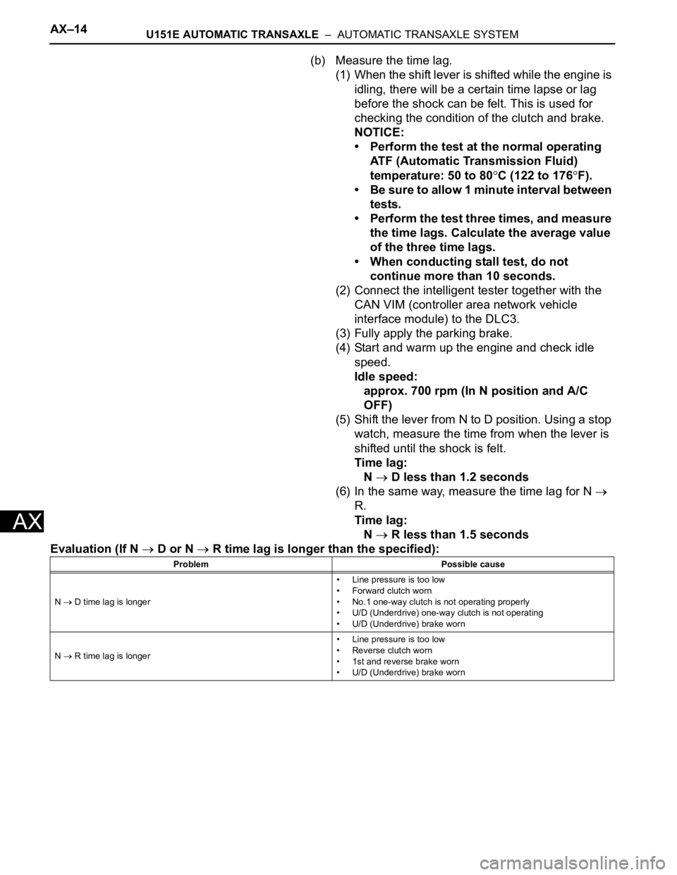
AX–14U151E AUTOMATIC TRANSAXLE – AUTOMATIC TRANSAXLE SYSTEM
AX
(b) Measure the time lag.
(1) When the shift lever is shifted while the engine is
idling, there will be a certain time lapse or lag
before the shock can be felt. This is used for
checking the condition of the clutch and brake.
NOTICE:
• Perform the test at the normal operating
ATF (Automatic Transmission Fluid)
temperature: 50 to 80
C (122 to 176F).
• Be sure to allow 1 minute interval between
tests.
• Perform the test three times, and measure
the time lags. Calculate the average value
of the three time lags.
• When conducting stall test, do not
continue more than 10 seconds.
(2) Connect the intelligent tester together with the
CAN VIM (controller area network vehicle
interface module) to the DLC3.
(3) Fully apply the parking brake.
(4) Start and warm up the engine and check idle
speed.
Idle speed:
approx. 700 rpm (In N position and A/C
OFF)
(5) Shift the lever from N to D position. Using a stop
watch, measure the time from when the lever is
shifted until the shock is felt.
Time lag:
N
D less than 1.2 seconds
(6) In the same way, measure the time lag for N
R.
Time lag:
N
R less than 1.5 seconds
Evaluation (If N
D or N R time lag is longer than the specified):
Problem Possible cause
N
D time lag is longer• Line pressure is too low
• Forward clutch worn
• No.1 one-way clutch is not operating properly
• U/D (Underdrive) one-way clutch is not operating
• U/D (Underdrive) brake worn
N
R time lag is longer• Line pressure is too low
• Reverse clutch worn
• 1st and reverse brake worn
• U/D (Underdrive) brake worn