2007 TOYOTA SIENNA stop start
[x] Cancel search: stop startPage 599 of 3000
ES–3062GR-FE ENGINE CONTROL SYSTEM – SFI SYSTEM
ES
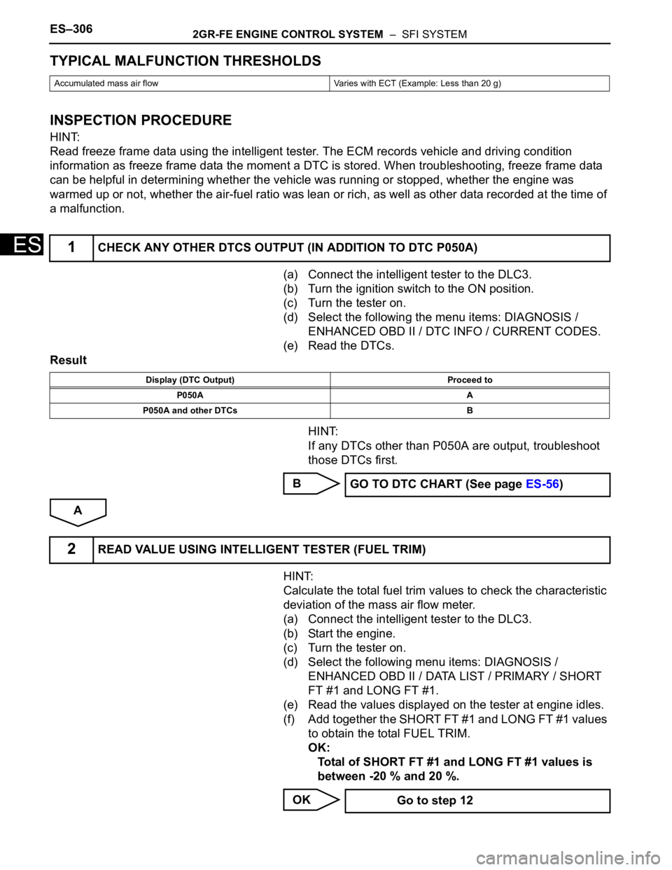
TYPICAL MALFUNCTION THRESHOLDS
INSPECTION PROCEDURE
HINT:
Read freeze frame data using the intelligent tester. The ECM records vehicle and driving condition
information as freeze frame data the moment a DTC is stored. When troubleshooting, freeze frame data
can be helpful in determining whether the vehicle was running or stopped, whether the engine was
warmed up or not, whether the air-fuel ratio was lean or rich, as well as other data recorded at the time of
a malfunction.
(a) Connect the intelligent tester to the DLC3.
(b) Turn the ignition switch to the ON position.
(c) Turn the tester on.
(d) Select the following the menu items: DIAGNOSIS /
ENHANCED OBD II / DTC INFO / CURRENT CODES.
(e) Read the DTCs.
Result
HINT:
If any DTCs other than P050A are output, troubleshoot
those DTCs first.
B
A
HINT:
Calculate the total fuel trim values to check the characteristic
deviation of the mass air flow meter.
(a) Connect the intelligent tester to the DLC3.
(b) Start the engine.
(c) Turn the tester on.
(d) Select the following menu items: DIAGNOSIS /
ENHANCED OBD II / DATA LIST / PRIMARY / SHORT
FT #1 and LONG FT #1.
(e) Read the values displayed on the tester at engine idles.
(f) Add together the SHORT FT #1 and LONG FT #1 values
to obtain the total FUEL TRIM.
OK:
Total of SHORT FT #1 and LONG FT #1 values is
between -20 % and 20 %.
OK
Accumulated mass air flow Varies with ECT (Example: Less than 20 g)
1CHECK ANY OTHER DTCS OUTPUT (IN ADDITION TO DTC P050A)
Display (DTC Output) Proceed to
P050A A
P050A and other DTCs B
GO TO DTC CHART (See page ES-56)
2READ VALUE USING INTELLIGENT TESTER (FUEL TRIM)
Go to step 12
Page 605 of 3000
ES–3122GR-FE ENGINE CONTROL SYSTEM – SFI SYSTEM
ES
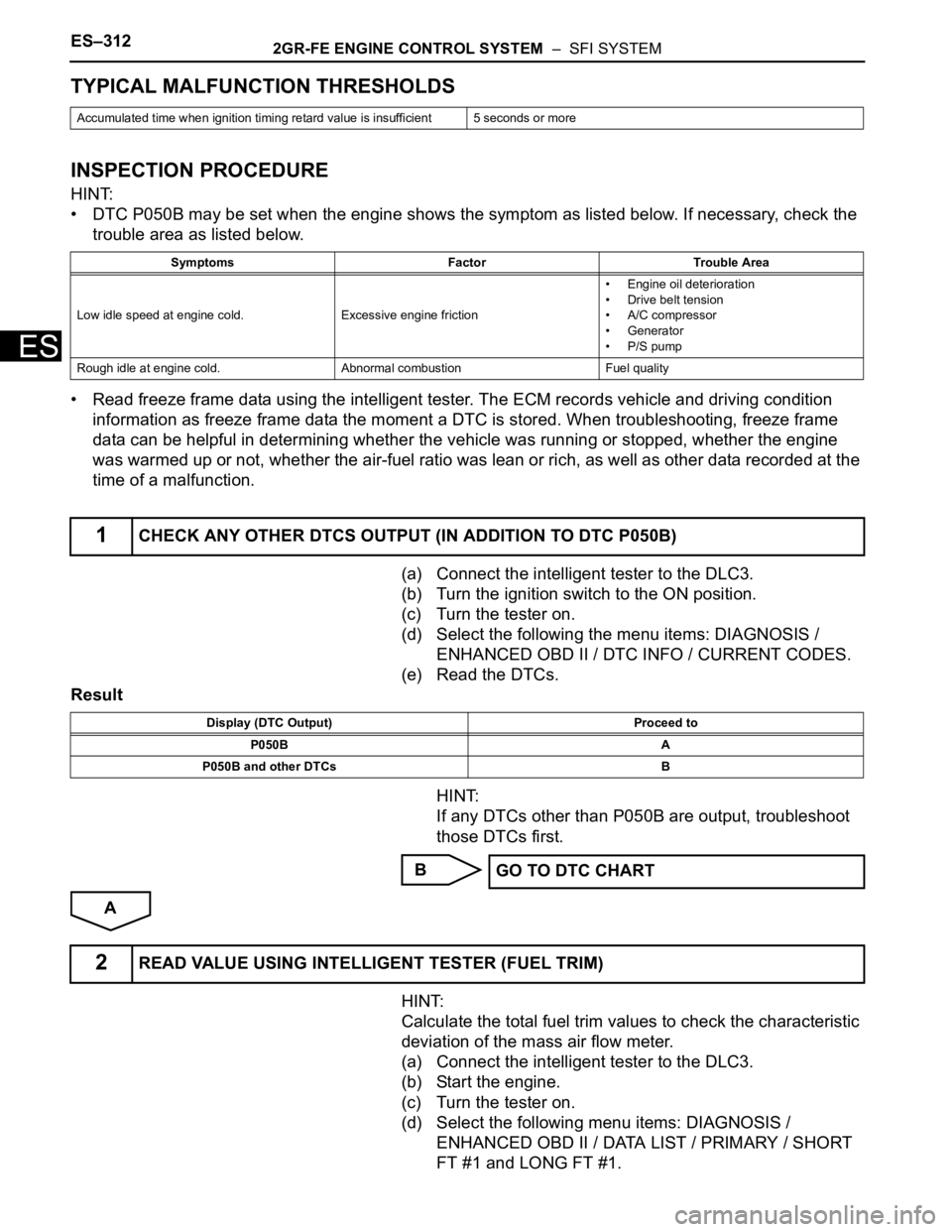
TYPICAL MALFUNCTION THRESHOLDS
INSPECTION PROCEDURE
HINT:
• DTC P050B may be set when the engine shows the symptom as listed below. If necessary, check the
trouble area as listed below.
• Read freeze frame data using the intelligent tester. The ECM records vehicle and driving condition
information as freeze frame data the moment a DTC is stored. When troubleshooting, freeze frame
data can be helpful in determining whether the vehicle was running or stopped, whether the engine
was warmed up or not, whether the air-fuel ratio was lean or rich, as well as other data recorded at the
time of a malfunction.
(a) Connect the intelligent tester to the DLC3.
(b) Turn the ignition switch to the ON position.
(c) Turn the tester on.
(d) Select the following the menu items: DIAGNOSIS /
ENHANCED OBD II / DTC INFO / CURRENT CODES.
(e) Read the DTCs.
Result
HINT:
If any DTCs other than P050B are output, troubleshoot
those DTCs first.
B
A
HINT:
Calculate the total fuel trim values to check the characteristic
deviation of the mass air flow meter.
(a) Connect the intelligent tester to the DLC3.
(b) Start the engine.
(c) Turn the tester on.
(d) Select the following menu items: DIAGNOSIS /
ENHANCED OBD II / DATA LIST / PRIMARY / SHORT
FT #1 and LONG FT #1.
Accumulated time when ignition timing retard value is insufficient 5 seconds or more
Symptoms Factor Trouble Area
Low idle speed at engine cold.Excessive engine friction• Engine oil deterioration
• Drive belt tension
• A/C compressor
• Generator
• P/S pump
Rough idle at engine cold. Abnormal combustion Fuel quality
1CHECK ANY OTHER DTCS OUTPUT (IN ADDITION TO DTC P050B)
Display (DTC Output) Proceed to
P050B A
P050B and other DTCs B
GO TO DTC CHART
2READ VALUE USING INTELLIGENT TESTER (FUEL TRIM)
Page 617 of 3000
ES–3242GR-FE ENGINE CONTROL SYSTEM – SFI SYSTEM
ES
(a) Connect the intelligent tester to the DLC3.
(b) Turn the ignition switch to the ON position.
(c) Turn the tester on.
(d) Clear the DTC.
(e) Turn the ignition switch off.
(f) Disconnect the battery negative terminal and wait for 1
minute.
(g) Connect the battery negative terminal.
(h) Start the engine.
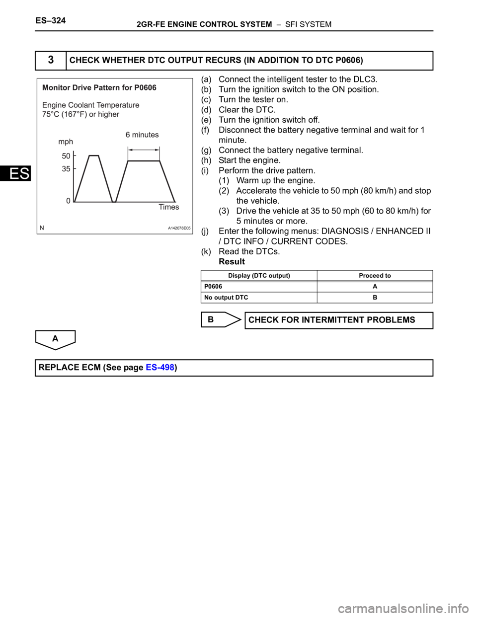
(i) Perform the drive pattern.
(1) Warm up the engine.
(2) Accelerate the vehicle to 50 mph (80 km/h) and stop
the vehicle.
(3) Drive the vehicle at 35 to 50 mph (60 to 80 km/h) for
5 minutes or more.
(j) Enter the following menus: DIAGNOSIS / ENHANCED II
/ DTC INFO / CURRENT CODES.
(k) Read the DTCs.
Result
B
A
3CHECK WHETHER DTC OUTPUT RECURS (IN ADDITION TO DTC P0606)
A142078E05
Display (DTC output) Proceed to
P0606 A
No output DTC B
CHECK FOR INTERMITTENT PROBLEMS
REPLACE ECM (See page ES-498)
Page 622 of 3000
2GR-FE ENGINE CONTROL SYSTEM – SFI SYSTEMES–329
ES
• Read freeze frame data using the intelligent tester. The ECM records vehicle and driving condition
information as freeze frame data the moment a DTC is stored. When troubleshooting, freeze frame
data can be helpful in determining whether the vehicle was running or stopped, whether the engine
was warmed up or not, whether the air-fuel ratio was lean or rich, as well as other data recorded at the
time of a malfunction.
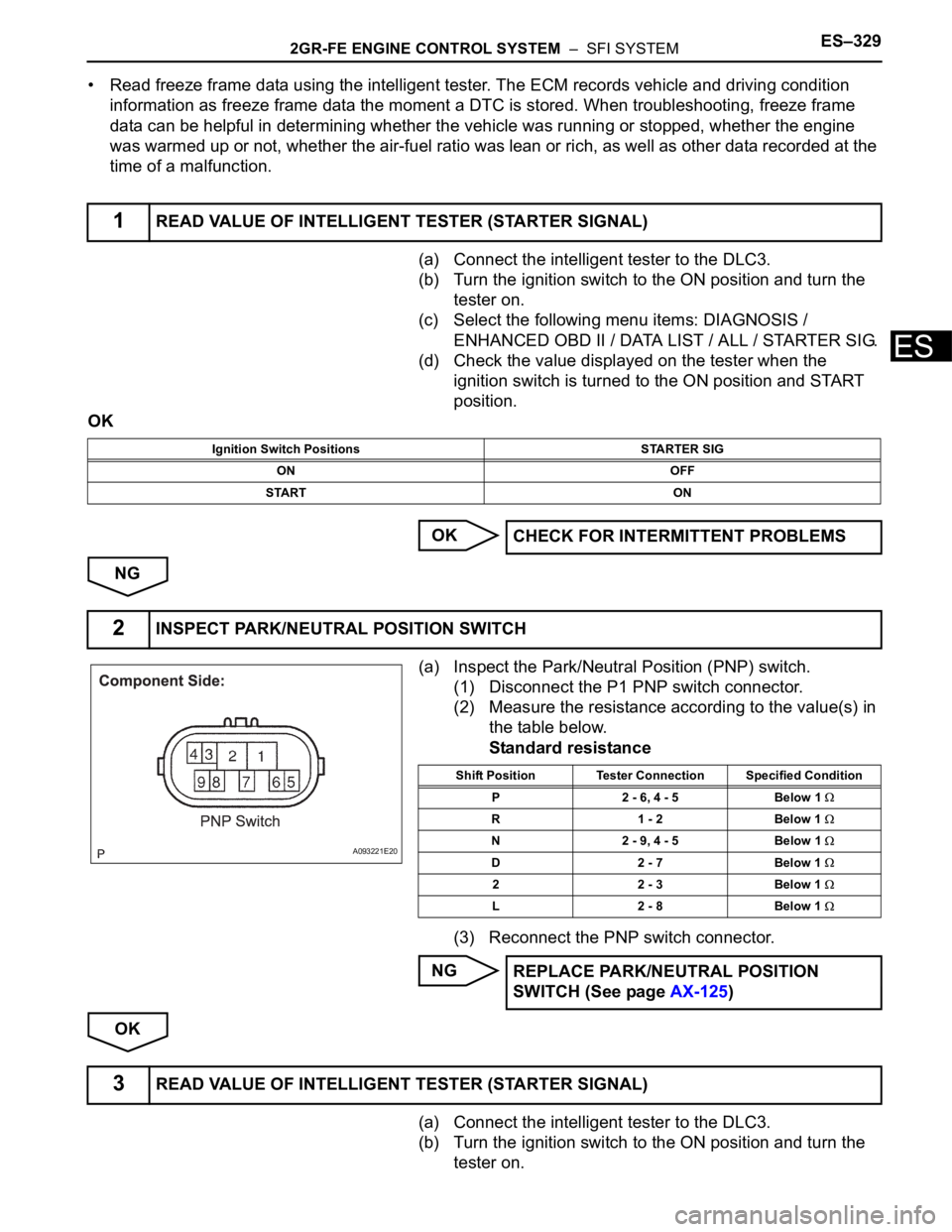
(a) Connect the intelligent tester to the DLC3.
(b) Turn the ignition switch to the ON position and turn the
tester on.
(c) Select the following menu items: DIAGNOSIS /
ENHANCED OBD II / DATA LIST / ALL / STARTER SIG.
(d) Check the value displayed on the tester when the
ignition switch is turned to the ON position and START
position.
OK
OK
NG
(a) Inspect the Park/Neutral Position (PNP) switch.
(1) Disconnect the P1 PNP switch connector.
(2) Measure the resistance according to the value(s) in
the table below.
Standard resistance
(3) Reconnect the PNP switch connector.
NG
OK
(a) Connect the intelligent tester to the DLC3.
(b) Turn the ignition switch to the ON position and turn the
tester on.
1READ VALUE OF INTELLIGENT TESTER (STARTER SIGNAL)
Ignition Switch Positions STARTER SIG
ON OFF
START ON
CHECK FOR INTERMITTENT PROBLEMS
2INSPECT PARK/NEUTRAL POSITION SWITCH
A093221E20
Shift Position Tester Connection Specified Condition
P 2 - 6, 4 - 5 Below 1
R 1 - 2 Below 1
N 2 - 9, 4 - 5 Below 1
D 2 - 7 Below 1
2 2 - 3 Below 1
L 2 - 8 Below 1
REPLACE PARK/NEUTRAL POSITION
SWITCH (See page AX-125)
3READ VALUE OF INTELLIGENT TESTER (STARTER SIGNAL)
Page 686 of 3000

2GR-FE ENGINE CONTROL SYSTEM – SFI SYSTEMES–393
ES
MONITOR DESCRIPTION
5 hours after the ignition switch is turned off, the soak timer activates the ECM to begin the EVAP system
monitor. While the engine is running, the ECM monitors the synchronization of the soak timer and the
CPU clock. If these two are not synchronized, the ECM interprets this as a malfunction, illuminates the
MIL and sets the DTC (2 trip detection logic).
MONITOR STRATEGY
TYPICAL ENABLING CONDITIONS
TYPICAL MALFUNCTION THRESHOLDS
INSPECTION PROCEDURE
HINT:
• DTC P2610 is set if an internal ECM problem is detected. Diagnostic procedures are not required.
ECM replacement is required.
• Read freeze frame data using the intelligent tester. The ECM records vehicle and driving condition
information as freeze frame data the moment a DTC is stored. When troubleshooting, freeze frame
data can be helpful in determining whether the vehicle was running or stopped, whether the engine
was warmed up or not, whether the air-fuel ratio was lean or rich, as well as other data recorded at the
time of a malfunction.
(a) Replace the ECM (See page ES-498).
NEXT
(a) Connect the intelligent tester to the DLC3.
(b) Turn the ignition switch to the ON position.
(c) Clear the DTCs (See page ES-39).
(d) Start the engine and wait for 10 minutes or more.
Required Sensors / Components ECM
Frequency of Operation Once per driving cycle
Duration 10 minutes
MIL Operation 2 driving cycles
Sequence of Operation None
The monitor will run whenever these DTCs are not
presentNone
Ignition switch ON
Engine Running
Battery voltage 8 V or more
Sta r t e r OF F
Soak timer measurement when ECM CPU clock counts
10 minutesLess than 7 minutes or more than 13 minutes
1REPLACE ECM
2CHECK WHETHER DTC OUTPUT RECURS
Page 725 of 3000
2GR-FE ENGINE CONTROL SYSTEM – SFI SYSTEMES–439
ES
A
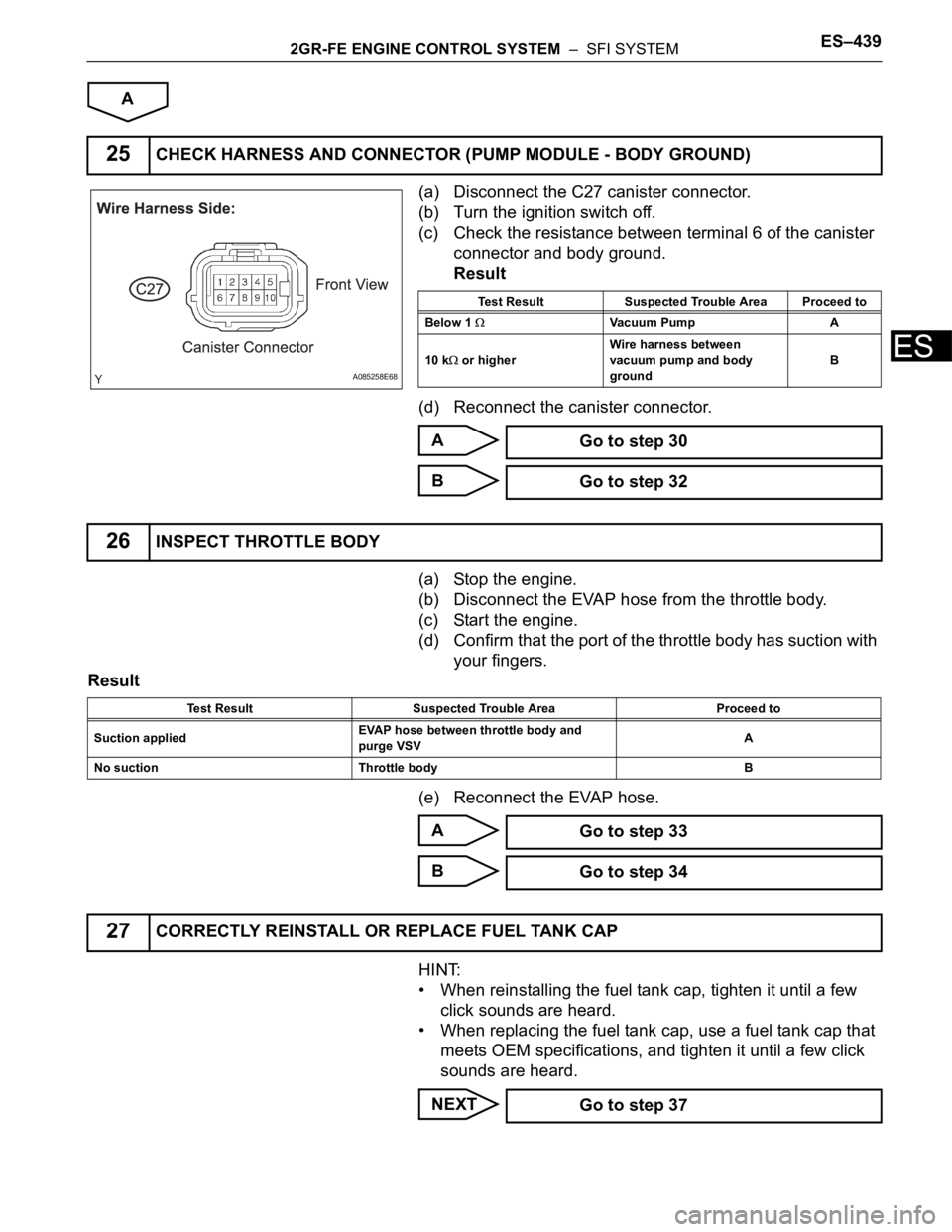
(a) Disconnect the C27 canister connector.
(b) Turn the ignition switch off.
(c) Check the resistance between terminal 6 of the canister
connector and body ground.
Result
(d) Reconnect the canister connector.
A
B
(a) Stop the engine.
(b) Disconnect the EVAP hose from the throttle body.
(c) Start the engine.
(d) Confirm that the port of the throttle body has suction with
your fingers.
Result
(e) Reconnect the EVAP hose.
A
B
HINT:
• When reinstalling the fuel tank cap, tighten it until a few
click sounds are heard.
• When replacing the fuel tank cap, use a fuel tank cap that
meets OEM specifications, and tighten it until a few click
sounds are heard.
NEXT
25CHECK HARNESS AND CONNECTOR (PUMP MODULE - BODY GROUND)
A085258E68
Test Result Suspected Trouble Area Proceed to
Below 1
Vacuum Pump A
10 k
or higherWire harness between
vacuum pump and body
groundB
Go to step 30
Go to step 32
26INSPECT THROTTLE BODY
Test Result Suspected Trouble Area Proceed to
Suction appliedEVAP hose between throttle body and
purge VSVA
No suction Throttle body B
Go to step 33
Go to step 34
27CORRECTLY REINSTALL OR REPLACE FUEL TANK CAP
Go to step 37
Page 777 of 3000

2GR-FE ENGINE CONTROL SYSTEM – SFI SYSTEMES–15
ES
BASIC INSPECTION
When a malfunction is not confirmed by the DTC check,
troubleshooting should be carried out in all circuits
considered to be possible causes of the problem. In many
cases, by carrying out the basic engine check shown in the
following flowchart, the location of the problem can be found
quickly and efficiently. Therefore, using this check is essential
when engine troubleshooting.
NOTICE:
Carry out this check with the engine stopped and ignition
switch off.
Result
NG
OK
NG
OK
NG
OK
(a) Visually check that the air filter is not excessively
contaminated with dirt or oil.
NG
OK
(a) Check the idling speed (See page EM-2).
1CHECK BATTERY VOLTAGE
Result Proceed to
11 V or more OK
Below 11 V NG
CHARGE OR REPLACE BATTERY
2CHECK WHETHER ENGINE CRANKS
PROCEED TO PROBLEM SYMPTOMS
TA B L E
3CHECK WHETHER ENGINE STARTS
GO TO STEP 6
4CHECK AIR FILTER
REPLACE AIR FILTER
5CHECK IDLING SPEED
Page 812 of 3000
ES–5042GR-FE ENGINE CONTROL SYSTEM – MASS AIR FLOW METER
ES
ON-VEHICLE INSPECTION
1. INSPECT MASS AIR FLOW METER
NOTICE:
• Perform the mass air flow (MAF) meter inspection
by following the procedures below.
• Only replace the MAF meter when the MAF value
in the DATA LIST (with the engine stopped) are
not within the normal operating range or there is
foreign matter on the MAF meter platinum hot
wire (heater).
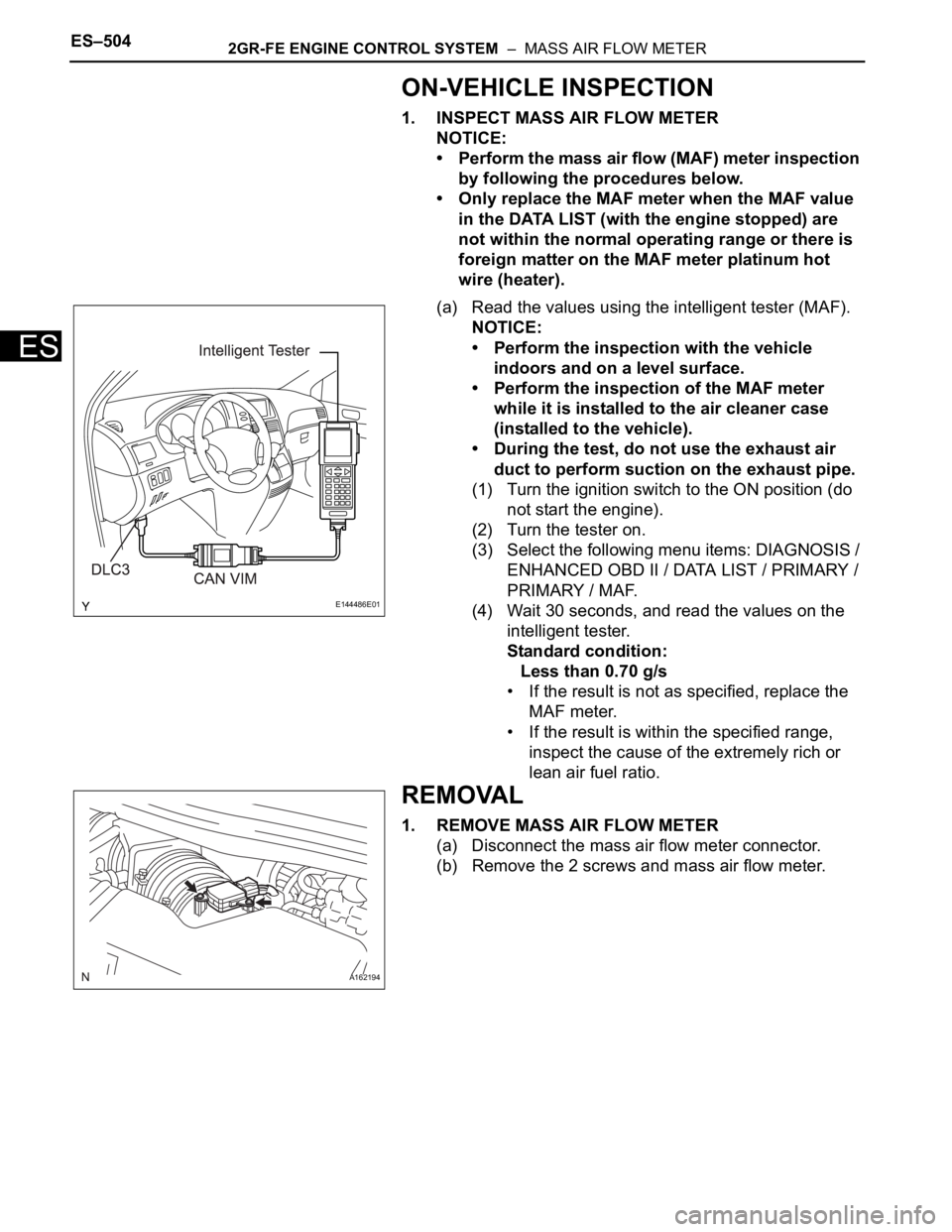
(a) Read the values using the intelligent tester (MAF).
NOTICE:
• Perform the inspection with the vehicle
indoors and on a level surface.
• Perform the inspection of the MAF meter
while it is installed to the air cleaner case
(installed to the vehicle).
• During the test, do not use the exhaust air
duct to perform suction on the exhaust pipe.
(1) Turn the ignition switch to the ON position (do
not start the engine).
(2) Turn the tester on.
(3) Select the following menu items: DIAGNOSIS /
ENHANCED OBD II / DATA LIST / PRIMARY /
PRIMARY / MAF.
(4) Wait 30 seconds, and read the values on the
intelligent tester.
Standard condition:
Less than 0.70 g/s
• If the result is not as specified, replace the
MAF meter.
• If the result is within the specified range,
inspect the cause of the extremely rich or
lean air fuel ratio.
REMOVAL
1. REMOVE MASS AIR FLOW METER
(a) Disconnect the mass air flow meter connector.
(b) Remove the 2 screws and mass air flow meter.
E144486E01
A162194