2007 TOYOTA SIENNA stop start
[x] Cancel search: stop startPage 453 of 3000

2GR-FE ENGINE CONTROL SYSTEM – SFI SYSTEMES–147
ES
DESCRIPTION
Refer to DTC P0115 (See page ES-133).
MONITOR DESCRIPTION
The ECT sensor is used to monitor the ECT. The ECT sensor has a built-in thermistor with a resistance
that varies according to the temperature of the engine coolant. When the ECT becomes low, the
resistance of the thermistor increases. When the temperature becomes high, the resistance drops. These
variations in the resistance are reflected in the voltage output from the ECT sensor.
The ECM monitors the sensor voltage and uses this value to calculate the ECT. If the sensor voltage
output deviates from the normal operating range, the ECM interprets this deviation as a malfunction in the
ECT sensor and sets the DTC.
Examples:
• Upon starting the engine, the ECT is between 35
C and 60C (95F and 140F). If the ECT remains
within 3
C (5.4F) of the stating temperature after driving for 250 seconds, the DTC is set (2 trip
detection logic).
• Upon starting the engine, the ECT is over 60
C (140F). If the ECT remains within 1C (1.8F) of the
starting temperature after driving for 250 seconds, the DTC is set (6 trip detection logic).
MONITOR STRATEGY
DTC P0116Engine Coolant Temperature Circuit Range /
Performance Problem
DTC No. DTC Detection Condition Trouble Area
P0116ECTs as listed below are nearly same (2 trip detection
logic):
– ECT when engine is started at lower than 60
C
(140
F) of ECT
– ECT when engine is warmed up
•Thermostat
• ECT sensor ECTs as listed below are nearly same when engine is
started at higher than 60
C (140F) of ECT (2 trip
detection logic)
– ECT when engine is stopped after driving
– ECT when engine is started at lower than 60
C
(140F) of ECT
When either of following conditions is met (2 trip
detection logic):
• When cold engine started and engine warmed up,
Engine Coolant Temperature (ECT) sensor value
does not change
• After engine is warmed up, ECT sensor value does
not change when engine stopped and then next
cold engine start is performed
Related DTCsP0116: Engine coolant temperature sensor output stuck at low engine coolant
temperature
P0116: Engine coolant temperature sensor output stuck at high engine coolant
temperature
Required Sensors / Components (Main) Engine Coolant Temperature (ECT) sensor
Required Sensors / Components (Related) Crankshaft position sensor, intake air temperature sensor and mass air flow meter
Frequency of Operation Continuous
Duration 5 hours
MIL Operation 2 driving cycles
Sequence of Operation None
Page 454 of 3000

ES–1482GR-FE ENGINE CONTROL SYSTEM – SFI SYSTEM
ES
TYPICAL ENABLING CONDITIONS
All:
ECT sensor cold start monitor:
ECT sensor soak monitor:
TYPICAL MALFUNCTION THRESHOLDS
ECT sensor cold start monitor:
ECT sensor soak monitor:
COMPONENT OPERATING RANGE
INSPECTION PROCEDURE
HINT:
• If any of DTC P0115, P0117, P0118 or P0125 are set simultaneously with DTC P0116, the ECT sensor
may have an open or a short circuit. Troubleshoot those DTCs first.
• Read freeze frame data using the intelligent tester. The ECM records vehicle and driving condition
information as freeze frame data the moment a DTC is stored. When troubleshooting, freeze frame
data can be helpful in determining whether the vehicle was running or stopped, whether the engine
was warmed up or not, whether the air-fuel ratio was lean or rich, as well as other data recorded at the
time of a malfunction.
(a) Connect the intelligent tester to the DLC3.
(b) Turn the ignition switch to the ON position.
(c) Turn the tester on.
(d) Enter the following menus: DIAGNOSIS / ENHANCED II
/ DTC INFO / CURRENT CODES.
(e) Read the DTC.
Monitor will run whenever these DTCs are not present. P0100, P0102, P0103 (MAF Sensor)
Battery voltage 10.5 V or more
Time after engine start 1 second or more
ECT at engine start Less than 60
C (140F)
IAT sensor circuit OK
Soak time 5 hours or more
Accumulated MAF 1421.2 g or more
Engine Running
Fuel cut OFF
Difference between ECT at engine start and IAT Less than 40
C (72F)
Battery voltage 10.5 V or more
Engine Running
Soak time 5 hours or more
ECT at engine start 60
C (140F) or more
Accumulated MAF 3298.1 g or more
ECT sensor value change Less than 5
C (9F)
ECT sensor value change Less than 5
C (9F)
Engine coolant temperature Varies with actual engine coolant temperature
1CHECK ANY OTHER DTCS OUTPUT (IN ADDITION TO DTC P0166)
Page 472 of 3000

ES–1662GR-FE ENGINE CONTROL SYSTEM – SFI SYSTEM
ES
TYPICAL ENABLING CONDITIONS
TYPICAL MALFUNCTION THRESHOLDS
INSPECTION PROCEDURE
HINT:
Read freeze frame data using the intelligent tester. The ECM records vehicle and driving condition
information as freeze frame data the moment a DTC is stored. When troubleshooting, freeze frame data
can be helpful in determining whether the vehicle was running or stopped, whether the engine was
warmed up or not, whether the air-fuel ratio was lean or rich, as well as other data recorded at the time of
a malfunction.
(a) Connect the intelligent tester to the DLC3.
(b) Turn the ignition switch to the ON position.
(c) Turn the tester on.
(d) Select the following menu items: DIAGNOSIS /
ENHANCED OBD II / DTC INFO / CURRENT CODES.
(e) Read the DTCs.
Required Sensors / Components (Related)Engine Coolant Temperature (ECT) sensor, Intake Air Temperature (IAT) sensor,
Vehicle speed sensor
Frequency of Operation Once per driving cycle
Duration 900 seconds
MIL Operation 2 driving cycles
Sequence of Operation None
The monitor will run whenever these DTCs are not
presentP0010, P0020 (VVT VSV 1, 2), P0011, P0012 (VVT System 1-Advance, Retard),
P0021, P0022 (VVT System 2-Adavance, Retard), P0031, P0032, P0051, P0052 (A/
F Sensor Heater Sensor 1), P0100, P0101, P0102, P0103 (MAF Sensor), P0110,
P0112, P0113 (IAT Sensor), P0115, P0116, P0117, P0118 (ECT Sensor), P0125
(Insufficient ECT for Closed Loop), P0136, P0156 (O2 Sensor 2), P0171, P0172
(Fuel System), P0300, P0301, P0302, P0303, P0304, P0305, P0306 (Misfire),
P0335 (CKP Sensor), P0340 (CMP sensor), P0345 (VVT sensor), P0351, P0352,
P0353, P0354, P0355, P0356 (Ignitor), P0500 (VSS), P2196, P2198(A/F Sensor
(Rationality)), P2A00, P2A03 (A/F Sensor (Slow Response))
Battery voltage 11 V or more
Either of following conditions is met: Condition 1 or 2
1. All of following conditions are met: Conditions (a), (b) and (c)
(a) ECT at engine start - IAT at engine start -15 to 7
C (5 to 45F)
(b) ECT at engine start -10 to 56
C (14 to 133F)
(c) IAT at engine start -10 to 56
C (14 to 133F)
2. All of following conditions are met: Conditions (d), (e) and (f)
(d) ECT at engine start - IAT at engine start More than 7
C (45F)
(e) ECT at engine start 56
C (133F) or less
(f) IAT at engine start -10
C (14F) or more
Accumulated time that vehicle speed is 80 mph (128
km/h) or moreLess than 20 seconds
Duration that all of the following conditions 1 and 2 are
met5 seconds or more
1. Estimated ECT 75
C (167F) or more
2. ECT sensor output Less than 75
C (167F)
1CHECK ANY OTHER DTCS OUTPUT (IN ADDITION TO DTC P0128)
Page 487 of 3000

2GR-FE ENGINE CONTROL SYSTEM – SFI SYSTEMES–181
ES
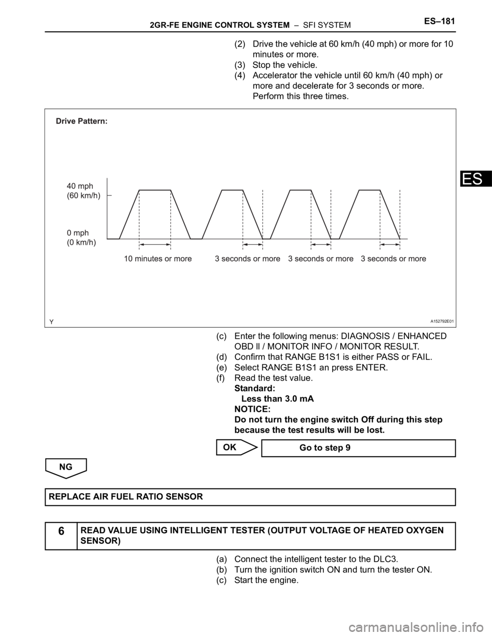
(2) Drive the vehicle at 60 km/h (40 mph) or more for 10
minutes or more.
(3) Stop the vehicle.
(4) Accelerator the vehicle until 60 km/h (40 mph) or
more and decelerate for 3 seconds or more.
Perform this three times.
(c) Enter the following menus: DIAGNOSIS / ENHANCED
OBD ll / MONITOR INFO / MONITOR RESULT.
(d) Confirm that RANGE B1S1 is either PASS or FAIL.
(e) Select RANGE B1S1 an press ENTER.
(f) Read the test value.
Standard:
Less than 3.0 mA
NOTICE:
Do not turn the engine switch Off during this step
because the test results will be lost.
OK
NG
(a) Connect the intelligent tester to the DLC3.
(b) Turn the ignition switch ON and turn the tester ON.
(c) Start the engine.
A152792E01
Go to step 9
REPLACE AIR FUEL RATIO SENSOR
6READ VALUE USING INTELLIGENT TESTER (OUTPUT VOLTAGE OF HEATED OXYGEN
SENSOR)
Page 516 of 3000

ES–2102GR-FE ENGINE CONTROL SYSTEM – SFI SYSTEM
ES
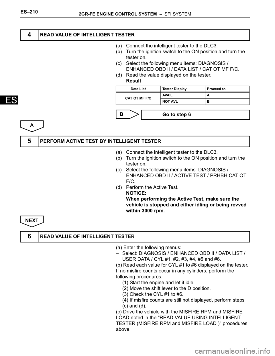
(a) Connect the intelligent tester to the DLC3.
(b) Turn the ignition switch to the ON position and turn the
tester on.
(c) Select the following menu items: DIAGNOSIS /
ENHANCED OBD II / DATA LIST / CAT OT MF F/C.
(d) Read the value displayed on the tester.
Result
B
A
(a) Connect the intelligent tester to the DLC3.
(b) Turn the ignition switch to the ON position and turn the
tester on.
(c) Select the following menu items: DIAGNOSIS /
ENHANCED OBD II / ACTIVE TEST / PRHBH CAT OT
F/C.
(d) Perform the Active Test.
NOTICE:
When performing the Active Test, make sure the
vehicle is stopped and either idling or being revved
within 3000 rpm.
NEXT
(a) Enter the following menus:
– Select: DIAGNOSIS / ENHANCED OBD II / DATA LIST /
USER DATA / CYL #1, #2, #3, #4, #5 and #6.
(b) Read each value for CYL #1 to #6 displayed on the tester.
If no misfire counts occur in any cylinders, perform the
following procedures:
(1) Start the engine and let it idle.
(2) Move the shift lever to the D position.
(3) Check the CYL #1 to #6.
(4) If misfire counts are still not displayed, perform steps
(c) and (d).
(c) Drive the vehicle with the MISFIRE RPM and MISFIRE
LOAD noted in the "READ VALUE USING INTELLIGENT
TESTER (MISFIRE RPM and MISFIRE LOAD )" procedures
above.
4READ VALUE OF INTELLIGENT TESTER
Data List Tester Display Proceed to
CAT OT MF F/CAVA I L A
NOT AVL B
Go to step 6
5PERFORM ACTIVE TEST BY INTELLIGENT TESTER
6READ VALUE OF INTELLIGENT TESTER
Page 537 of 3000

2GR-FE ENGINE CONTROL SYSTEM – SFI SYSTEMES–231
ES
INSPECTION PROCEDURE
HINT:
• If no problem is found by this diagnostic troubleshooting procedure, troubleshoot the engine
mechanical systems.
• Check the engine speed. The engine speed can be checked by using the intelligent tester. Perform the
following procedure:
(a) Connect the intelligent tester to the DLC3.
(b) Start the engine.
(c) Turn the tester on.
(d) Select the following menu items: DIAGNOSIS / ENHANCED OBD II / DATA LIST / PRIMARY /
ENGINE SPD.
The engine speed may be indicated as zero despite the engine revolving normally. This is caused
by a lack of NE signals from the Crankshaft Position (CKP) sensor. Alternatively, the engine speed
may be indicated as lower than the actual engine speed, if the CKP sensor voltage output is
insufficient.
• Read freeze frame data using the intelligent tester. The ECM records vehicle and driving condition
information as freeze frame data the moment a DTC is stored. When troubleshooting, freeze frame
data can be helpful in determining whether the vehicle was running or stopped, whether the engine
was warmed up or not, whether the air-fuel ratio was lean or rich, as well as other data recorded at the
time of a malfunction.
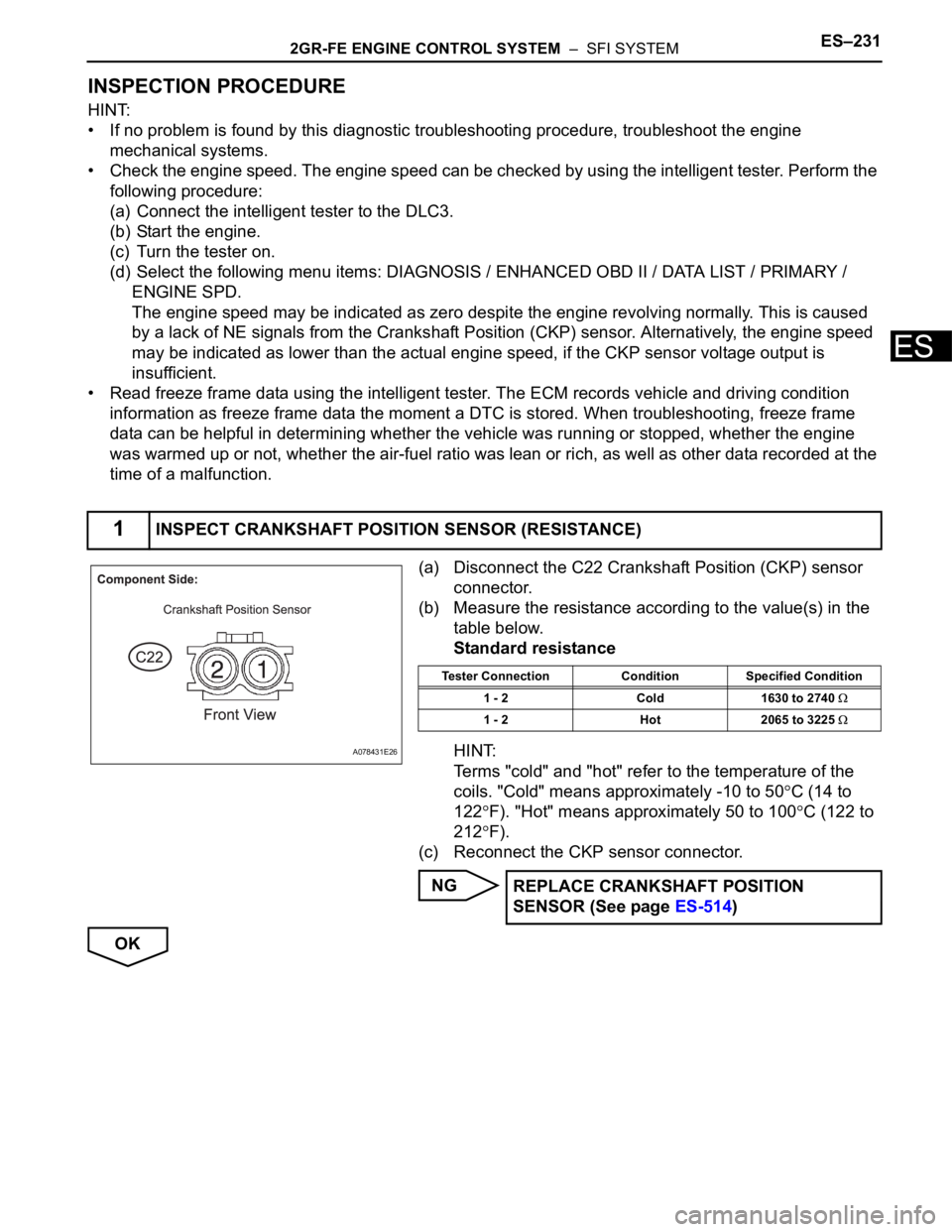
(a) Disconnect the C22 Crankshaft Position (CKP) sensor
connector.
(b) Measure the resistance according to the value(s) in the
table below.
Standard resistance
HINT:
Terms "cold" and "hot" refer to the temperature of the
coils. "Cold" means approximately -10 to 50
C (14 to
122
F). "Hot" means approximately 50 to 100C (122 to
212
F).
(c) Reconnect the CKP sensor connector.
NG
OK
1INSPECT CRANKSHAFT POSITION SENSOR (RESISTANCE)
A078431E26
Tester Connection Condition Specified Condition
1 - 2 Cold 1630 to 2740
1 - 2 Hot 2065 to 3225
REPLACE CRANKSHAFT POSITION
SENSOR (See page ES-514)
Page 585 of 3000

ES–2922GR-FE ENGINE CONTROL SYSTEM – SFI SYSTEM
ES
TYPICAL MALFUNCTION THRESHOLDS
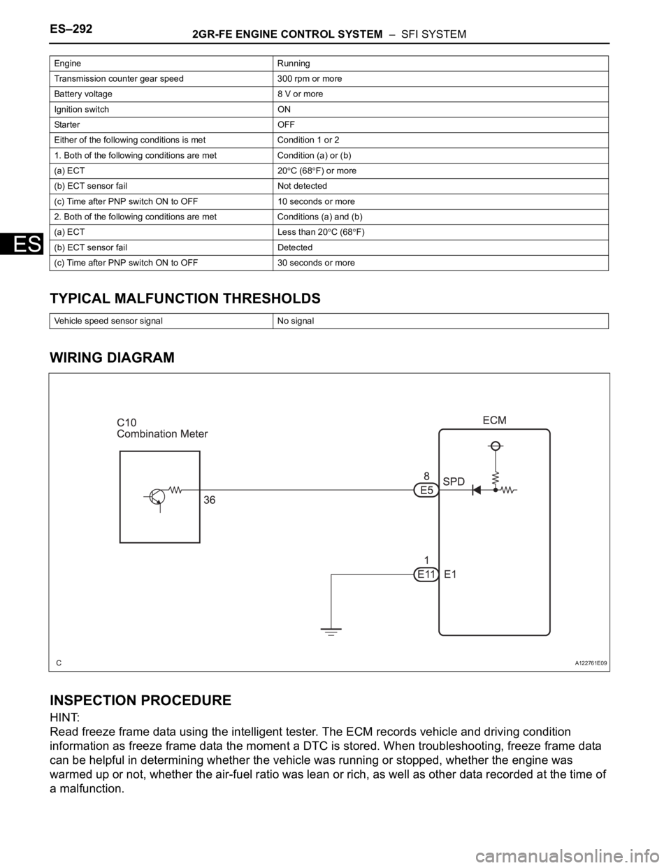
WIRING DIAGRAM
INSPECTION PROCEDURE
HINT:
Read freeze frame data using the intelligent tester. The ECM records vehicle and driving condition
information as freeze frame data the moment a DTC is stored. When troubleshooting, freeze frame data
can be helpful in determining whether the vehicle was running or stopped, whether the engine was
warmed up or not, whether the air-fuel ratio was lean or rich, as well as other data recorded at the time of
a malfunction.
Engine Running
Transmission counter gear speed 300 rpm or more
Battery voltage 8 V or more
Ignition switch ON
Starter OFF
Either of the following conditions is met Condition 1 or 2
1. Both of the following conditions are met Condition (a) or (b)
(a) ECT 20
C (68F) or more
(b) ECT sensor fail Not detected
(c) Time after PNP switch ON to OFF 10 seconds or more
2. Both of the following conditions are met Conditions (a) and (b)
(a) ECT Less than 20
C (68F)
(b) ECT sensor fail Detected
(c) Time after PNP switch ON to OFF 30 seconds or more
Vehicle speed sensor signal No signal
A122761E09
Page 589 of 3000

ES–2962GR-FE ENGINE CONTROL SYSTEM – SFI SYSTEM
ES
DESCRIPTION
The stop light switch is a duplex system that transmits two signals: STP and ST1-. These two signals are
used by the ECM to monitor whether or not the brake system is working properly. If the signals, which
indicate the brake pedal is being depressed or released, are detected simultaneously, the ECM interprets
this as a malfunction in the stop light switch and sets the DTC.
HINT:
The normal conditions are as shown in the table below. The signals can be read using the intelligent
tester.
MONITOR DESCRIPTION
This DTC indicates that the stop light switch remains on. When the stop light switch remains ON during
"stop and go" driving, the ECM interprets this as a fault in the stop light switch and the MIL comes on and
the ECM stores the DTC. The vehicle must stop (less than 2 mph (3 km/h)) and go (19 mph (30 km/h) or
more) 5 times for two driving cycles in order to detect a malfunction.
MONITOR STRATEGY
TYPICAL ENABLING CONDITIONS
DTC P0504 Brake Switch "A" / "B" Correlation
DTC P0724 Brake Switch "B" Circuit High
Signals Brake Pedal Released In Transition Brake Pedal Depressed
STP OFF ON ON
ST1- ON ON OFF
DTC No. DTC Detection Condition Trouble Area
P0504Conditions (a), (b) and (c) continue for 0.5 seconds or
more (1 trip detection logic):
(a) Ignition switch in the ON position
(b) Brake pedal released
(c) STP signal OFF when ST1- signal OFF• Short in stop light switch signal circuit
• STOP fuse
• Stop light switch
•ECM
P0724The stop light switch remains ON even when the
vehicle is driven in a STOP (less than 2 mph (3 km/h))
and GO (19 mph (30 km/h) or more) fashion 5 times. (2
trip detection logic)• Short in stop light switch signal circuit
• Stop light switch
•ECM
Related DTCs P0724: Stop light switch/Rationality
Required sensors/Components Stop light switch, Vehicle speed sensor
Frequency of operation Continuous
Duration GO and STOP 5 times
MIL operation 2 driving cycles
Sequence of operation None
The monitor will run whenever this DTC is not present None
Ignition switch ON
Starter OFF
Battery voltage 8 V or more
GO (Vehicle speed is 18.65 mph (30 km/h) or more) Once
STOP (Vehicle speed is less than 1.86 mph (3 km/h)) Once