2007 TOYOTA SIENNA stop start
[x] Cancel search: stop startPage 2439 of 3000
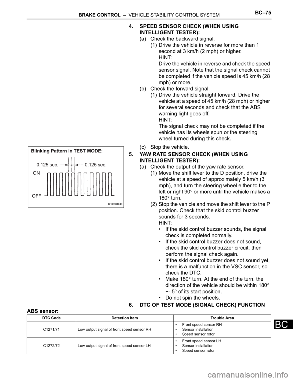
BRAKE CONTROL – VEHICLE STABILITY CONTROL SYSTEMBC–75
BC
4. SPEED SENSOR CHECK (WHEN USING
INTELLIGENT TESTER):
(a) Check the backward signal.
(1) Drive the vehicle in reverse for more than 1
second at 3 km/h (2 mph) or higher.
HINT:
Drive the vehicle in reverse and check the speed
sensor signal. Note that the signal check cannot
be completed if the vehicle speed is 45 km/h (28
mph) or more.
(b) Check the forward signal.
(1) Drive the vehicle straight forward. Drive the
vehicle at a speed of 45 km/h (28 mph) or higher
for several seconds and check that the ABS
warning light goes off.
HINT:
The signal check may not be completed if the
vehicle has its wheels spun or the steering
wheel turned during this check.
(c) Stop the vehicle.
5. YAW RATE SENSOR CHECK (WHEN USING
INTELLIGENT TESTER):
(a) Check the output of the yaw rate sensor.
(1) Move the shift lever to the D position, drive the
vehicle at a speed of approximately 5 km/h (3
mph), and turn the steering wheel either to the
left or right 90
or more until the vehicle makes a
180
turn.
(2) Stop the vehicle and move the shift lever to the P
position. Check that the skid control buzzer
sounds for 3 seconds.
HINT:
• If the skid control buzzer sounds, the signal
check is completed normally.
• If the skid control buzzer does not sound,
check the skid control buzzer circuit, then
perform the signal check again.
• If the skid control buzzer does not sound yet,
there is a malfunction in the VSC sensor, so
check the DTC.
• Make 180
turn. At the end of the turn, the
direction of the vehicle should be within 180
+- 5
of its start position.
• Do not spin the wheels.
6. DTC OF TEST MODE (SIGNAL CHECK) FUNCTION
ABS sensor:
BR03904E40
DTC Code Detection Item Trouble Area
C1271/71 Low output signal of front speed sensor RH• Front speed sensor RH
• Sensor installation
• Speed sensor rotor
C1272/72 Low output signal of front speed sensor LH• Front speed sensor LH
• Sensor installation
• Speed sensor rotor
Page 2442 of 3000

BC–78BRAKE CONTROL – VEHICLE STABILITY CONTROL SYSTEM
BC
9. SPEED SENSOR CHECK (WHEN USING SST CHECK
WIRE):
(a) Check the speed sensor signal.
(1) Drive the vehicle straight forward. Drive the
vehicle at a speed of 45 km/h (28 mph) or higher
for several seconds and check that the ABS
warning light goes off.
HINT:
The signal check may not be completed if the
vehicle has its wheels spun or the steering
wheel turned during this check.
(b) Stop the vehicle.
NOTICE:
• Before performing the speed sensor signal
check, complete the deceleration sensor and
master cylinder pressure sensor checks.
• The speed sensor signal check may not be
completed if the speed sensor signal check is
started while turning the steering wheel or
spinning the wheels.
• After the ABS warning light goes off, if
vehicle speed exceeds 80 km/h (50 mph), a
signal check code will be stored again.
Decelerate or stop the vehicle before the
speed reaches 80 km/h (50 mph).
• If the signal check has not been completed,
the ABS warning light blinks while driving
and the ABS system does not operate.
HINT:
When the signal check has been completed, the
ABS warning light goes off while driving and blinks
in the test mode pattern while stationary.
10. YAW RATE SENSOR CHECK (WHEN USING SST
CHECK WIRE):
(a) Check the zero point voltage of the yaw rate sensor.
(1) Keep the vehicle in a stationary condition on a
level surface for 1 second or more.
(b) Check the output of the yaw rate sensor.
(1) Move the shift lever to the D position, drive the
vehicle at a speed of approximately 3 mph (5
km/h), and turn the steering wheel either to the
left or right 90
or more until the vehicle makes
180
turn.
(2) Stop the vehicle and move the shift lever to the
position. Check that the skid control buzzer
sounds for 3 seconds.
HINT:
• If the skid control buzzer sounds, the signal
check is completed normally.
• If the skid control buzzer does not sound,
check the skid control buzzer circuit, then
perform the signal check again.
Page 2443 of 3000

BRAKE CONTROL – VEHICLE STABILITY CONTROL SYSTEMBC–79
BC
• If the skid control buzzer does not sound yet,
there is a malfunction in the yaw rate sensor,
so check the DTC.
• Make a 180
turn. At the end of the turn, the
direction of the vehicle should be within 180
+- 5
of its start position.
• Do not spin the wheels.
11. DTC OF TEST MODE (SIGNAL CHECK) FUNCTION
ABS sensor:
VSC sensor:
HINT:
The codes in this table are output only in Test Mode
(signal check).
DTC Code Detection Item Trouble Area
C1271/71 Low output signal of front speed sensor RH• Front speed sensor RH
• Sensor installation
• Speed sensor rotor
C1272/72 Low output signal of front speed sensor LH• Front speed sensor LH
• Sensor installation
• Speed sensor rotor
C1273/73 Low output signal of rear speed sensor RH• Rear speed sensor RH
• Sensor installation
• Speed sensor rotor
C1274/74 Low output signal of rear speed sensor LH• Rear speed sensor LH
• Sensor installation
• Speed sensor rotor
C1275/75Abnormal change in output signal of front speed sensor
RHSpeed sensor rotor
C1276/76Abnormal change in output signal of front speed sensor
LHSpeed sensor rotor
C1277/77Abnormal change in output signal of rear speed sensor
RHSpeed sensor rotor
C1278/78Abnormal change in output signal of rear speed sensor
LHSpeed sensor rotor
C1279/79 Acceleration sensor output voltage malfunction• Yaw rate and deceleration sensor
• Sensor installation
C1281/81 Master cylinder pressure sensor output malfunction• Stop light switch
• Master cylinder pressure sensor
DTC Code Detection Item Trouble Area
C0371/71 Yaw rate sensor Yaw rate and deceleration sensor
Page 2493 of 3000

BRAKE CONTROL – VEHICLE STABILITY CONTROL SYSTEMBC–131
BC
DESCRIPTION
Master cylinder pressure sensor is connected to the skid control ECU in the actuator.
INSPECTION PROCEDURE
(a) Connect the intelligent tester to the DLC3.
(b) Start the engine.
(c) Select the DATA LIST mode on the intelligent tester.
ABS / VSC:
(d) Check that the brake fluid pressure value of the master
cylinder pressure sensor indicated on the intelligent
tester, changes when the brake pedal is depressed.
OK:
Brake fluid pressure value should change.
NOTICE:
When replacing the brake actuator assembly,
perform zero point calibration (See page BC-70).
NG
OK
DTC C1246/46 Master Cylinder Pressure Sensor Malfunction
DTC Code DTC Detection Condition Trouble Area
C1246/46When any of the following is detected:
1. When the vehicle speed is 7 km/h (4 mph) or more
and PMC terminal voltage of skid control ECU
exceeds 0.86 V, the condition that the voltage does
not change by 0.005 V or more continues for 30
sec.
2. Noise in terminal PMC of skid control ECU occurs 7
times or more within 5 sec.
3. When the stop light switch is off, the condition that
PMC terminal voltage of skid control ECU is 0.86 V
or more, or less than 0.3 V continues for 5 sec. or
more.
4. When IG1 terminal voltage is between 9.5 and 17.2
V, the condition that the VCM terminal voltage of
skid control ECU is out of the range from 4.4 to 5.6
V continues for 1.2 sec. or more.
5. When VCM terminal voltage of skid control ECU is
between 4.4 and 5.6 V, the condition that the PMC
terminal voltage of skid control ECU is out of the
range from 0.14 to 4.85 V continues for 1.2 sec. or
more.• Master cylinder pressure sensor
• Master cylinder pressure sensor circuit
1READ VALUE ON INTELLIGENT TESTER (MASTER CYLINDER PRESSURE SENSOR)
Tester Display Measurement Item/Range Normal Condition
MAS CYL PRS 1Master cylinder pressure sensor 1 reading /
min.: 0 V, max.: 5 VWhen brake pedal is released : 0.3 to 0.9 V
Go to step 2
REPLACE BRAKE ACTUATOR ASSEMBLY
Page 2568 of 3000
BC–32BRAKE CONTROL – ANTI-LOCK BRAKE SYSTEM
BC
(a) Clear the DTCs (See page BC-10).
(b) Start the engine.
(c) Drive the vehicle at the speed of 4 mph (6 km/h) or more.
(d) Check that the same DTCs are recorded (See page BC-
10).
HINT:
If a speed signal of 4 mph (6 km/h) or more is input to the
skid control ECU, with the ignition switch on and the stop
light switch off, the ECU performs self-diagnosis of the
motor and solenoid circuits.
Result
HINT:
• If any DTCs are output while jiggling a connector or
wire harness of the brake actuator (skid control ECU),
inspect and repair the connector or wire harness.
• If the normal system code is output, slightly jiggle the
connectors, wire harnesses, and fuses of the brake
actuator assembly. Make sure that no DTCs are
output.
• These DTCs may be stored due to a malfunction in
the connector terminal connection, etc.
B
A
Condition Proceed to
DTCs (C0226/21, C0236/22, C0246/23 and C0256/24) are output A
DTCs (C0226/21, C0236/22, C0246/23 and C0256/24) are not
outputB
END
REPLACE BRAKE ACTUATOR ASSEMBLY
Page 2573 of 3000
BRAKE CONTROL – ANTI-LOCK BRAKE SYSTEMBC–35
BC
(f) Check operating sound of the ABS motor when
operating it with the intelligent tester.
OK:
The operating sound of the ABS motor is heard.
NG
OK
(a) Clear the DTCs (See page BC-10).
(b) Start the engine.
(c) Drive the vehicle at the speed of 6 km/h (4 mph) or more.
(d) Check that the same DTCs are recorded (See page BC-
10).
HINT:
• Reinstall the sensors, connectors, etc. and restore the
vehicle to its prior condition before rechecking for
DTCs.
• If a speed signal of 6 km/h (4 mph) or more is input to
the skid control ECU, with the ignition switch on and
the stop light switch off, the ECU performs self-
diagnosis of the motor and solenoid circuits.
Result
HINT:
• If any DTCs are output while jiggling a connector or
wire harness of the brake actuator (skid control ECU),
inspect and repair the connector or wire harness.
• If the normal system code is output, slightly jiggle the
connectors, wire harnesses, and fuses of the brake
actuator assembly. Make sure that no DTCs are
output.
• These DTCs may be stored due to a malfunction in
the connector terminal connection, etc.
B
AREPLACE BRAKE ACTUATOR ASSEMBLY
5RECONFIRM DTC
Condition Proceed to
DTCs (C0273/13 and C0274/14) are output A
DTCs (C0273/13 and C0274/14) are not output B
END
REPLACE BRAKE ACTUATOR ASSEMBLY
Page 2577 of 3000
BRAKE CONTROL – ANTI-LOCK BRAKE SYSTEMBC–37
BC
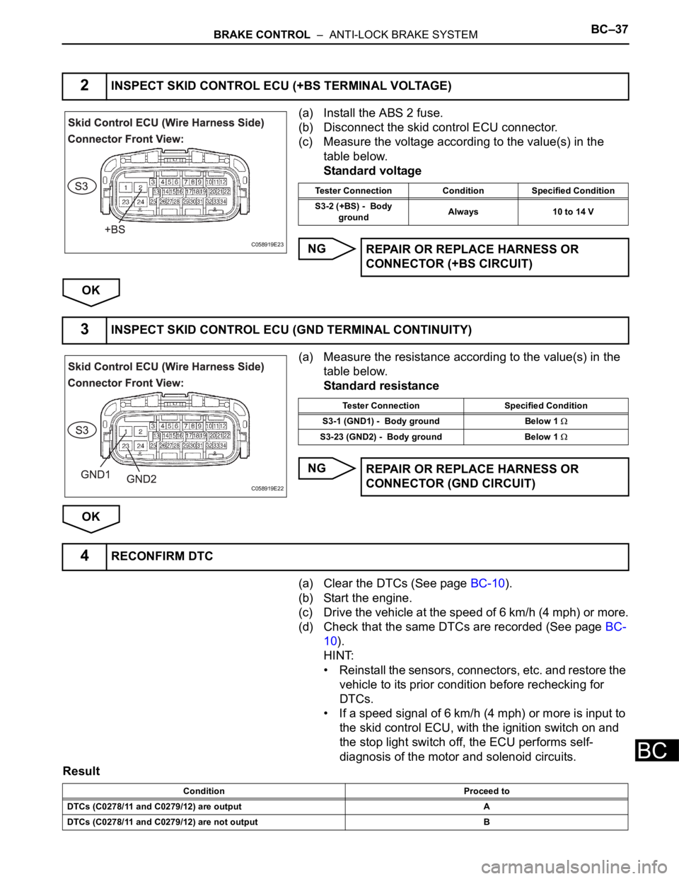
(a) Install the ABS 2 fuse.
(b) Disconnect the skid control ECU connector.
(c) Measure the voltage according to the value(s) in the
table below.
Standard voltage
NG
OK
(a) Measure the resistance according to the value(s) in the
table below.
Standard resistance
NG
OK
(a) Clear the DTCs (See page BC-10).
(b) Start the engine.
(c) Drive the vehicle at the speed of 6 km/h (4 mph) or more.
(d) Check that the same DTCs are recorded (See page BC-
10).
HINT:
• Reinstall the sensors, connectors, etc. and restore the
vehicle to its prior condition before rechecking for
DTCs.
• If a speed signal of 6 km/h (4 mph) or more is input to
the skid control ECU, with the ignition switch on and
the stop light switch off, the ECU performs self-
diagnosis of the motor and solenoid circuits.
Result
2INSPECT SKID CONTROL ECU (+BS TERMINAL VOLTAGE)
C058919E23
Tester Connection Condition Specified Condition
S3-2 (+BS) - Body
groundAlways 10 to 14 V
REPAIR OR REPLACE HARNESS OR
CONNECTOR (+BS CIRCUIT)
3INSPECT SKID CONTROL ECU (GND TERMINAL CONTINUITY)
C058919E22
Tester Connection Specified Condition
S3-1 (GND1) - Body ground Below 1
S3-23 (GND2) - Body ground Below 1
REPAIR OR REPLACE HARNESS OR
CONNECTOR (GND CIRCUIT)
4RECONFIRM DTC
Condition Proceed to
DTCs (C0278/11 and C0279/12) are output A
DTCs (C0278/11 and C0279/12) are not output B
Page 2596 of 3000
BR–4BRAKE – BRAKE FLUID
BR
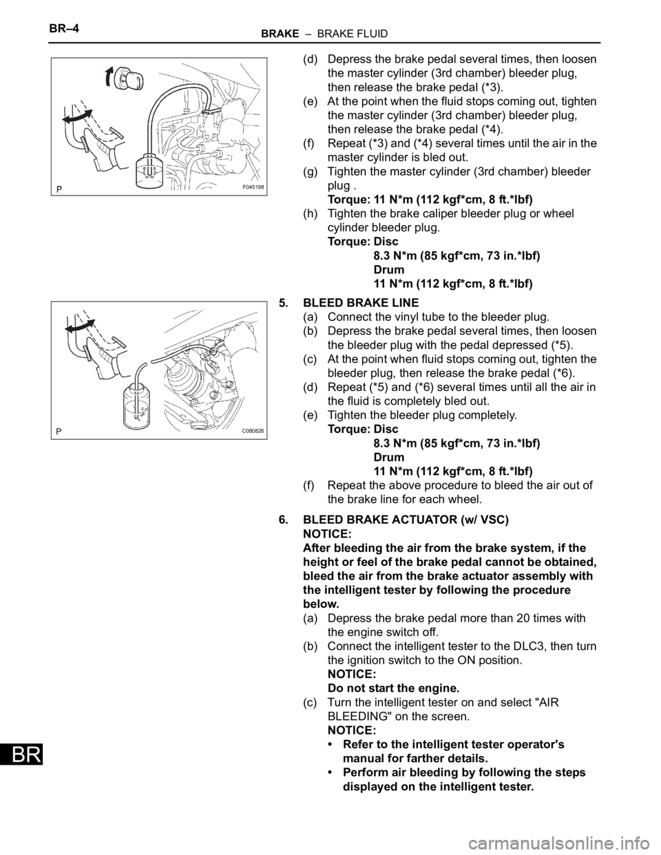
(d) Depress the brake pedal several times, then loosen
the master cylinder (3rd chamber) bleeder plug,
then release the brake pedal (*3).
(e) At the point when the fluid stops coming out, tighten
the master cylinder (3rd chamber) bleeder plug,
then release the brake pedal (*4).
(f) Repeat (*3) and (*4) several times until the air in the
master cylinder is bled out.
(g) Tighten the master cylinder (3rd chamber) bleeder
plug .
Torque: 11 N*m (112 kgf*cm, 8 ft.*lbf)
(h) Tighten the brake caliper bleeder plug or wheel
cylinder bleeder plug.
Torque: Disc
8.3 N*m (85 kgf*cm, 73 in.*lbf)
Drum
11 N*m (112 kgf*cm, 8 ft.*lbf)
5. BLEED BRAKE LINE
(a) Connect the vinyl tube to the bleeder plug.
(b) Depress the brake pedal several times, then loosen
the bleeder plug with the pedal depressed (*5).
(c) At the point when fluid stops coming out, tighten the
bleeder plug, then release the brake pedal (*6).
(d) Repeat (*5) and (*6) several times until all the air in
the fluid is completely bled out.
(e) Tighten the bleeder plug completely.
Torque: Disc
8.3 N*m (85 kgf*cm, 73 in.*lbf)
Drum
11 N*m (112 kgf*cm, 8 ft.*lbf)
(f) Repeat the above procedure to bleed the air out of
the brake line for each wheel.
6. BLEED BRAKE ACTUATOR (w/ VSC)
NOTICE:
After bleeding the air from the brake system, if the
height or feel of the brake pedal cannot be obtained,
bleed the air from the brake actuator assembly with
the intelligent tester by following the procedure
below.
(a) Depress the brake pedal more than 20 times with
the engine switch off.
(b) Connect the intelligent tester to the DLC3, then turn
the ignition switch to the ON position.
NOTICE:
Do not start the engine.
(c) Turn the intelligent tester on and select "AIR
BLEEDING" on the screen.
NOTICE:
• Refer to the intelligent tester operator's
manual for farther details.
• Perform air bleeding by following the steps
displayed on the intelligent tester.
F045198
C080826