2007 TOYOTA SIENNA transmission
[x] Cancel search: transmissionPage 789 of 3000
2GR-FE ENGINE CONTROL SYSTEM – THROTTLE BODYES–493
ES
ON-VEHICLE INSPECTION
1. INSPECT THROTTLE BODY
(a) Listen to the throttle control motor operating sounds.
(1) Turn the ignition switch to the ON position.
(2) When pressing the accelerator pedal position
sensor lever, listen to the running motor. Make
sure that no friction noise comes from the
motor.
If friction noise exists, replace the throttle body.
(b) Inspect the throttle position sensor.
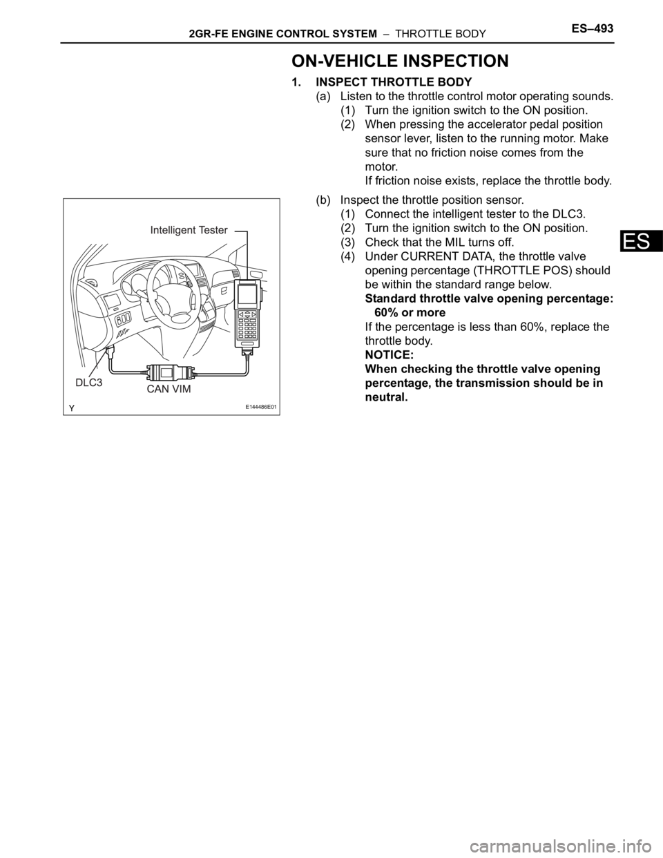
(1) Connect the intelligent tester to the DLC3.
(2) Turn the ignition switch to the ON position.
(3) Check that the MIL turns off.
(4) Under CURRENT DATA, the throttle valve
opening percentage (THROTTLE POS) should
be within the standard range below.
Standard throttle valve opening percentage:
60% or more
If the percentage is less than 60%, replace the
throttle body.
NOTICE:
When checking the throttle valve opening
percentage, the transmission should be in
neutral.
E144486E01
Page 804 of 3000

ES–282GR-FE ENGINE CONTROL SYSTEM – SFI SYSTEM
ES
• Vehicle was driven in the city area (or on free-
way) for 10 minutes or more.
(b) Monitor Conditions
(1) Turn the ignition switch off and wait for 6 hours.
HINT:
Do not start the engine until checking Readiness
Monitor status. If the engine is started, the step
described above must be repeated.
(c) Monitor Status
(1) Connect an intelligent tester to the DLC3.
(2) Turn the ignition switch to the ON position.
(3) Turn the tester or scan tool ON.
(4) Check the Readiness Monitor status displayed
on the tester or scan tool.
If the status does not switch to COMPL
(complete), restart the engine, make sure that
the preconditions have been met, and then
perform the Monitor Conditions again.
4. A/F SENSOR AND HO2S MONITORS
(a) Preconditions
The monitor will not run unless:
• 2 minutes or more have elapsed since the engine
was started.
• The Engine Coolant Temperature (ECT) is 75
C
(167
F) or more.
• Cumulative driving time at a vehicle speed of 30
mph (48 km/h) or more exceeds 6 minutes.
• Air-fuel ratio feedback control is performed.
• Fuel-cut control is performed for 8 seconds or
more (for the Rear HO2 Sensor Monitor).
(b) Drive Pattern for front A/F sensor and HO2 sensor.
(1) Connect an intelligent tester to the DLC3.
(2) Turn the ignition switch to the ON position.
(3) Turn the tester ON.
(4) Clear the DTCs.
(5) Start the engine, and warm it up until the ECT
reaches 75
C (167F) or higher.
(6) Drive the vehicle at 38 mph (60 km/h) or more
for at least 10 minutes.
(7) Change the transmission to the 2nd gear.
(8) Accelerate the vehicle to 40 mph (64 km/h) or
more by depressing the accelerator pedal for at
least 10 seconds (Procedure "A").
(9) Soon after performing procedure "A" above,
release the accelerator pedal for at least 4
seconds without depressing the brake pedal, in
order to execute fuel-cut control (Procedure "B").
(10) Allow the vehicle to decelerate until the vehicle
speed declines to less than 6 mph (10 km/h)
(Procedure "C").
(11) Repeat procedures from "A" through "C" above
at least 3 times in one driving cycle.
Page 824 of 3000
ES–422GR-FE ENGINE CONTROL SYSTEM – SFI SYSTEM
ES
In order to enhance OBD function on vehicles and
develop the Off-Board diagnosis system, CAN
communication is introduced in this system (CAN:
Controller Area Network). It minimizes a gap
between technician skills and vehicle technology.
CAN is a network, which uses a pair of data
transmission lines, spanning multiple computers
and sensors. It allows a high speed communication
between the systems and to simplify the wire
harness connection.
Since this system is equipped with the CAN
communication, connecting the CAN VIM (VIM:
Vehicle Interface Module) with an intelligent tester is
necessary to display any information from the ECM.
(Also the communication between the intelligent
tester and the ECM uses CAN communication
signal.) When confirming the DTCs and any data of
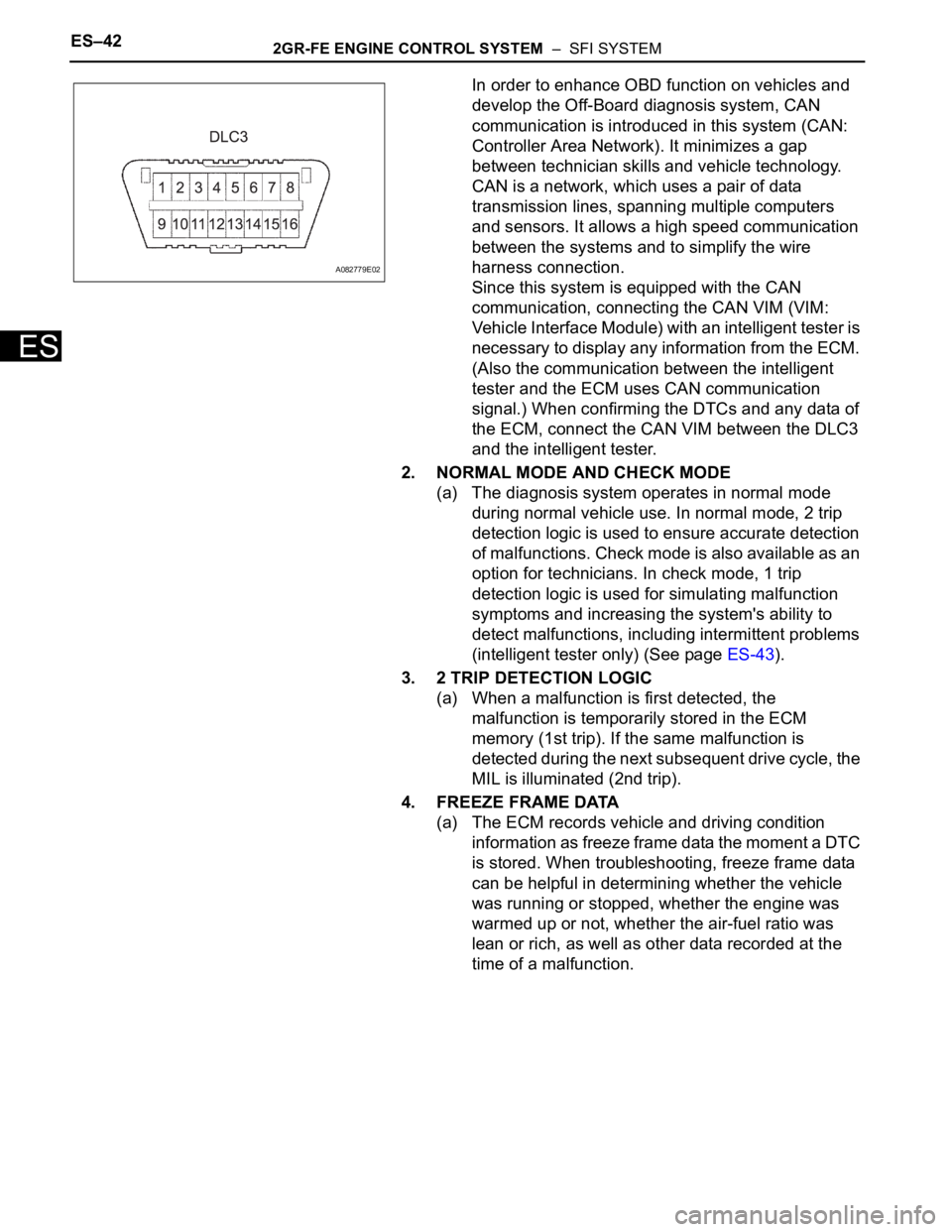
the ECM, connect the CAN VIM between the DLC3
and the intelligent tester.
2. NORMAL MODE AND CHECK MODE
(a) The diagnosis system operates in normal mode
during normal vehicle use. In normal mode, 2 trip
detection logic is used to ensure accurate detection
of malfunctions. Check mode is also available as an
option for technicians. In check mode, 1 trip
detection logic is used for simulating malfunction
symptoms and increasing the system's ability to
detect malfunctions, including intermittent problems
(intelligent tester only) (See page ES-43).
3. 2 TRIP DETECTION LOGIC
(a) When a malfunction is first detected, the
malfunction is temporarily stored in the ECM
memory (1st trip). If the same malfunction is
detected during the next subsequent drive cycle, the
MIL is illuminated (2nd trip).
4. FREEZE FRAME DATA
(a) The ECM records vehicle and driving condition
information as freeze frame data the moment a DTC
is stored. When troubleshooting, freeze frame data
can be helpful in determining whether the vehicle
was running or stopped, whether the engine was
warmed up or not, whether the air-fuel ratio was
lean or rich, as well as other data recorded at the
time of a malfunction.
A082779E02
Page 825 of 3000
2GR-FE ENGINE CONTROL SYSTEM – SFI SYSTEMES–43
ES
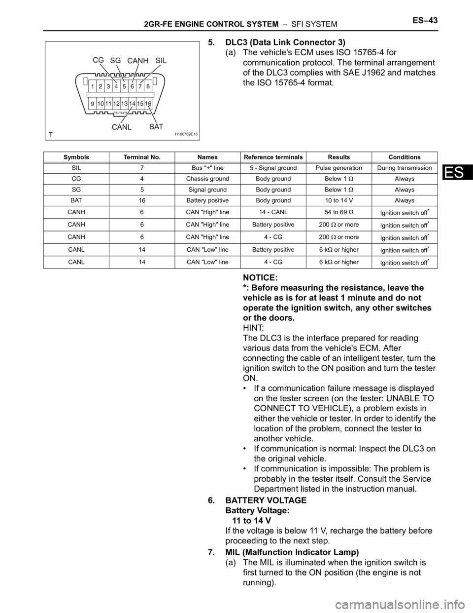
5. DLC3 (Data Link Connector 3)
(a) The vehicle's ECM uses ISO 15765-4 for
communication protocol. The terminal arrangement
of the DLC3 complies with SAE J1962 and matches
the ISO 15765-4 format.
NOTICE:
*: Before measuring the resistance, leave the
vehicle as is for at least 1 minute and do not
operate the ignition switch, any other switches
or the doors.
HINT:
The DLC3 is the interface prepared for reading
various data from the vehicle's ECM. After
connecting the cable of an intelligent tester, turn the
ignition switch to the ON position and turn the tester
ON.
• If a communication failure message is displayed
on the tester screen (on the tester: UNABLE TO
CONNECT TO VEHICLE), a problem exists in
either the vehicle or tester. In order to identify the
location of the problem, connect the tester to
another vehicle.
• If communication is normal: Inspect the DLC3 on
the original vehicle.
• If communication is impossible: The problem is
probably in the tester itself. Consult the Service
Department listed in the instruction manual.
6. BATTERY VOLTAGE
Battery Voltage:
11 to 14 V
If the voltage is below 11 V, recharge the battery before
proceeding to the next step.
7. MIL (Malfunction Indicator Lamp)
(a) The MIL is illuminated when the ignition switch is
first turned to the ON position (the engine is not
running).
H100769E16
Symbols Terminal No. Names Reference terminals Results Conditions
SIL 7 Bus "+" line 5 - Signal ground Pulse generation During transmission
CG 4 Chassis ground Body ground Below 1
Always
SG 5 Signal ground Body ground Below 1
Always
BAT 16 Battery positive Body ground 10 to 14 V Always
CANH 6 CAN "High" line 14 - CANL 54 to 69
Ignition switch off*
CANH 6 CAN "High" line Battery positive 200 or more
Ignition switch off*
CANH 6 CAN "High" line 4 - CG 200 or more
Ignition switch off*
CANL 14 CAN "Low" line Battery positive 6 k or higher
Ignition switch off*
CANL 14 CAN "Low" line 4 - CG 6 k or higher
Ignition switch off*
Page 872 of 3000
2GR-FE ENGINE MECHANICAL – ENGINE ASSEMBLYEM–55
EM
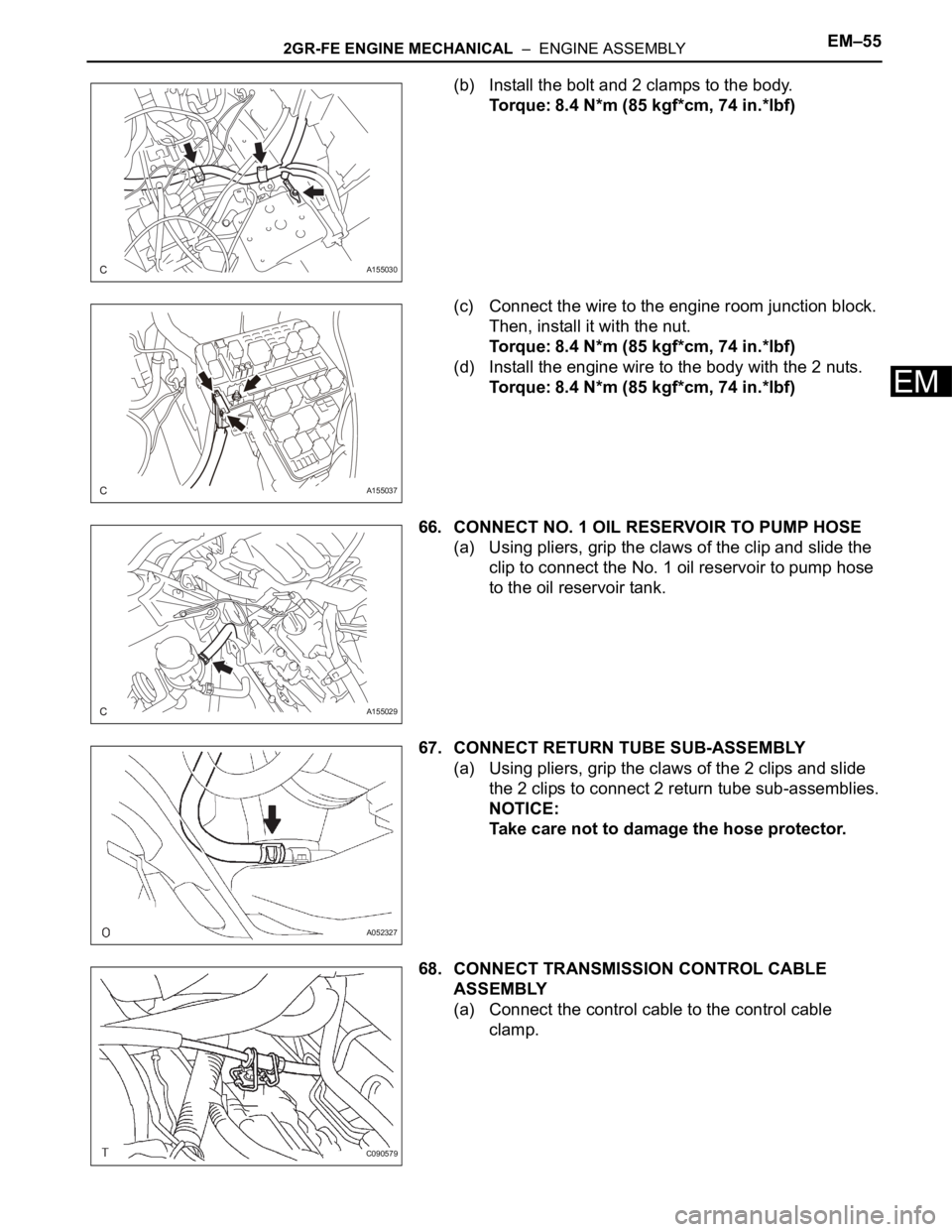
(b) Install the bolt and 2 clamps to the body.
Torque: 8.4 N*m (85 kgf*cm, 74 in.*lbf)
(c) Connect the wire to the engine room junction block.
Then, install it with the nut.
Torque: 8.4 N*m (85 kgf*cm, 74 in.*lbf)
(d) Install the engine wire to the body with the 2 nuts.
Torque: 8.4 N*m (85 kgf*cm, 74 in.*lbf)
66. CONNECT NO. 1 OIL RESERVOIR TO PUMP HOSE
(a) Using pliers, grip the claws of the clip and slide the
clip to connect the No. 1 oil reservoir to pump hose
to the oil reservoir tank.
67. CONNECT RETURN TUBE SUB-ASSEMBLY
(a) Using pliers, grip the claws of the 2 clips and slide
the 2 clips to connect 2 return tube sub-assemblies.
NOTICE:
Take care not to damage the hose protector.
68. CONNECT TRANSMISSION CONTROL CABLE
ASSEMBLY
(a) Connect the control cable to the control cable
clamp.
A155030
A155037
A155029
A052327
C090579
Page 873 of 3000
EM–562GR-FE ENGINE MECHANICAL – ENGINE ASSEMBLY
EM
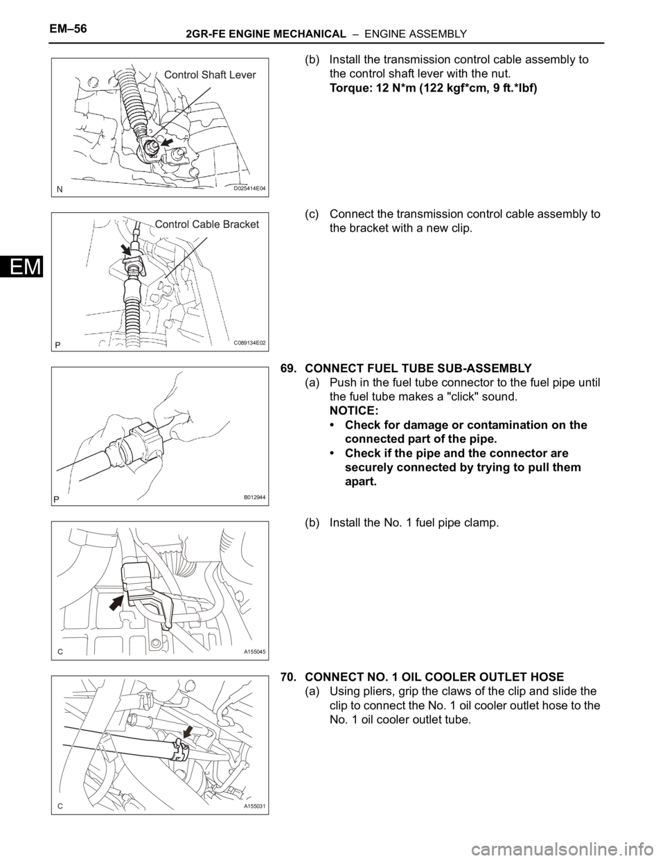
(b) Install the transmission control cable assembly to
the control shaft lever with the nut.
Torque: 12 N*m (122 kgf*cm, 9 ft.*lbf)
(c) Connect the transmission control cable assembly to
the bracket with a new clip.
69. CONNECT FUEL TUBE SUB-ASSEMBLY
(a) Push in the fuel tube connector to the fuel pipe until
the fuel tube makes a "click" sound.
NOTICE:
• Check for damage or contamination on the
connected part of the pipe.
• Check if the pipe and the connector are
securely connected by trying to pull them
apart.
(b) Install the No. 1 fuel pipe clamp.
70. CONNECT NO. 1 OIL COOLER OUTLET HOSE
(a) Using pliers, grip the claws of the clip and slide the
clip to connect the No. 1 oil cooler outlet hose to the
No. 1 oil cooler outlet tube.
D025414E04
C089134E02
B012944
A155045
A155031
Page 932 of 3000
EM–22GR-FE ENGINE MECHANICAL – ENGINE
EM
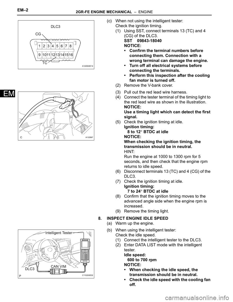
(c) When not using the intelligent tester:
Check the ignition timing.
(1) Using SST, connect terminals 13 (TC) and 4
(CG) of the DLC3.
SST 09843-18040
NOTICE:
• Confirm the terminal numbers before
connecting them. Connection with a
wrong terminal can damage the engine.
• Turn off all electrical systems before
connecting the terminals.
• Perform this inspection after the cooling
fan motor is turned off.
(2) Remove the V-bank cover.
(3) Pull out the red lead wire harness.
(4) Connect the tester terminal of the timing light to
the red lead wire as shown in the illustration.
NOTICE:
Use a timing light which can detect the first
signal.
(5) Check the ignition timing at idle.
Ignition timing:
8 to 12
BTDC at idle
NOTICE:
When checking the ignition timing, the
transmission should be in neutral.
HINT:
Run the engine at 1000 to 1300 rpm for 5
seconds, and then check that the engine rpm
returns to idle speed.
(6) Disconnect terminals 13 (TC) and 4 (CG) of the
DLC3.
(7) Check the ignition timing at idle.
Ignition timing:
7 to 24
BTDC at idle
(8) Confirm that the ignition timing moves to the
advanced angle side when the engine rpm is
increased.
(9) Remove the timing light.
8. INSPECT ENGINE IDLE SPEED
(a) Warm up the engine.
(b) When using the intelligent tester:
Check the idle speed.
(1) Connect the intelligent tester to the DLC3.
(2) Enter DATA LIST mode with the intelligent
tester.
Idle speed:
600 to 700 rpm
NOTICE:
• When checking the idle speed, the
transmission should be in neutral.
• Check the idle speed with the cooling fan
off.
A122830E14
A132997
C110200E02
Page 990 of 3000
2GR-FE ENGINE MECHANICAL – ENGINE ASSEMBLYEM–31
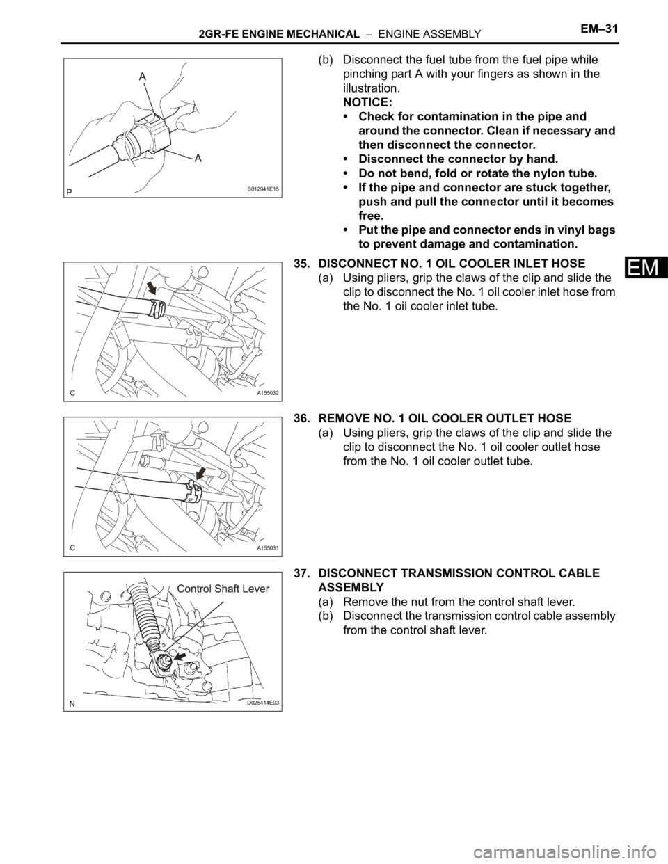
EM
(b) Disconnect the fuel tube from the fuel pipe while
pinching part A with your fingers as shown in the
illustration.
NOTICE:
• Check for contamination in the pipe and
around the connector. Clean if necessary and
then disconnect the connector.
• Disconnect the connector by hand.
• Do not bend, fold or rotate the nylon tube.
• If the pipe and connector are stuck together,
push and pull the connector until it becomes
free.
• Put the pipe and connector ends in vinyl bags
to prevent damage and contamination.
35. DISCONNECT NO. 1 OIL COOLER INLET HOSE
(a) Using pliers, grip the claws of the clip and slide the
clip to disconnect the No. 1 oil cooler inlet hose from
the No. 1 oil cooler inlet tube.
36. REMOVE NO. 1 OIL COOLER OUTLET HOSE
(a) Using pliers, grip the claws of the clip and slide the
clip to disconnect the No. 1 oil cooler outlet hose
from the No. 1 oil cooler outlet tube.
37. DISCONNECT TRANSMISSION CONTROL CABLE
ASSEMBLY
(a) Remove the nut from the control shaft lever.
(b) Disconnect the transmission control cable assembly
from the control shaft lever.
B012941E15
A155032
A155031
D025414E03