2007 TOYOTA SIENNA transmission
[x] Cancel search: transmissionPage 2352 of 3000

TW–34TIRE AND WHEEL – TIRE PRESSURE WARNING SYSTEM
TW
DIAGNOSIS SYSTEM
1. CHECK BATTERY VOLTAGE
Standard voltage:
11 to 14 V
If the voltage is below 11 V, recharge the battery before
proceeding.
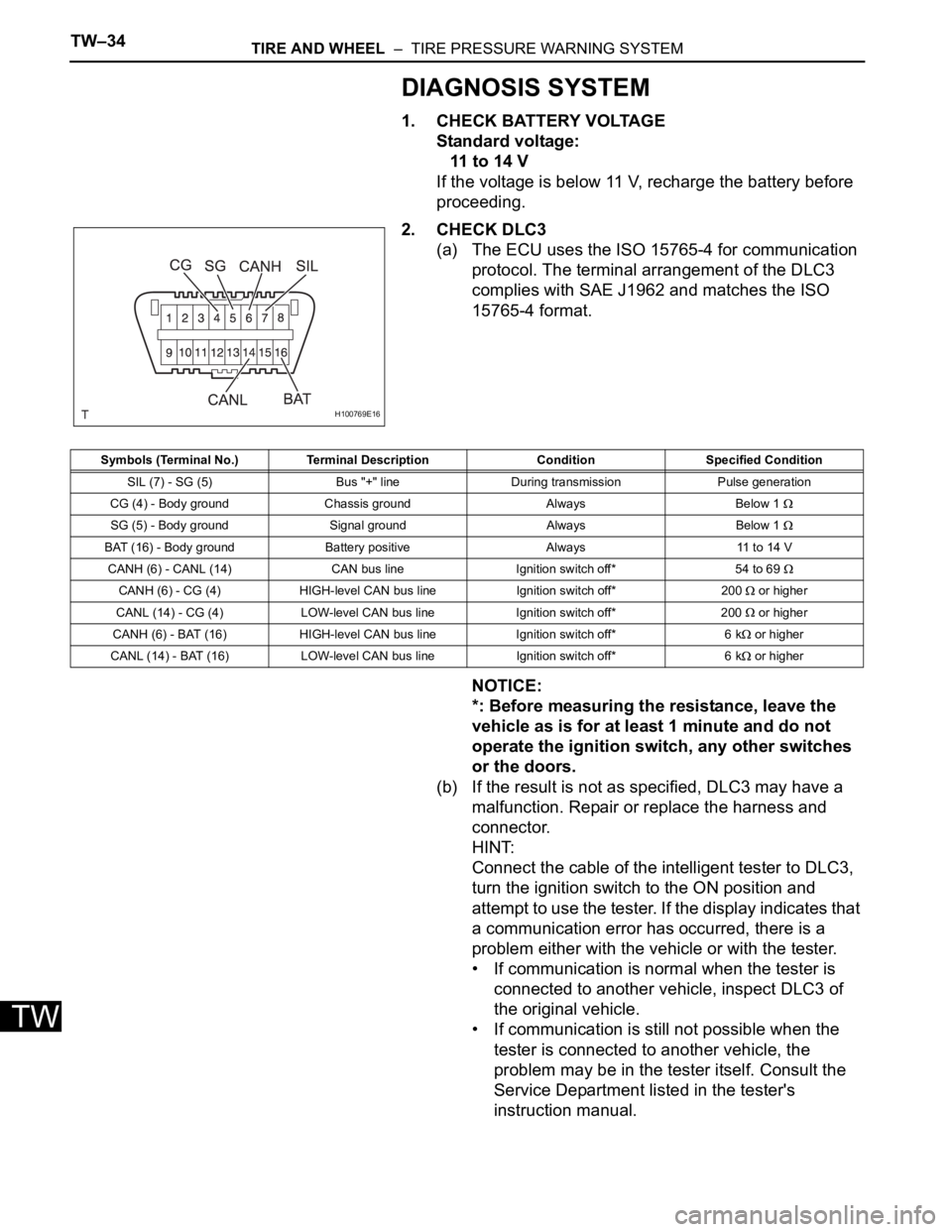
2. CHECK DLC3
(a) The ECU uses the ISO 15765-4 for communication
protocol. The terminal arrangement of the DLC3
complies with SAE J1962 and matches the ISO
15765-4 format.
NOTICE:
*: Before measuring the resistance, leave the
vehicle as is for at least 1 minute and do not
operate the ignition switch, any other switches
or the doors.
(b) If the result is not as specified, DLC3 may have a
malfunction. Repair or replace the harness and
connector.
HINT:
Connect the cable of the intelligent tester to DLC3,
turn the ignition switch to the ON position and
attempt to use the tester. If the display indicates that
a communication error has occurred, there is a
problem either with the vehicle or with the tester.
• If communication is normal when the tester is
connected to another vehicle, inspect DLC3 of
the original vehicle.
• If communication is still not possible when the
tester is connected to another vehicle, the
problem may be in the tester itself. Consult the
Service Department listed in the tester's
instruction manual.
H100769E16
Symbols (Terminal No.) Terminal Description Condition Specified Condition
SIL (7) - SG (5) Bus "+" line During transmission Pulse generation
CG (4) - Body ground Chassis ground Always Below 1
SG (5) - Body ground Signal ground Always Below 1
BAT (16) - Body ground Battery positive Always 11 to 14 V
CANH (6) - CANL (14) CAN bus line Ignition switch off* 54 to 69
CANH (6) - CG (4) HIGH-level CAN bus line Ignition switch off* 200 or higher
CANL (14) - CG (4) LOW-level CAN bus line Ignition switch off* 200
or higher
CANH (6) - BAT (16) HIGH-level CAN bus line Ignition switch off* 6 k
or higher
CANL (14) - BAT (16) LOW-level CAN bus line Ignition switch off* 6 k
or higher
Page 2356 of 3000

TW–38TIRE AND WHEEL – TIRE PRESSURE WARNING SYSTEM
TW
DATA LIST / ACTIVE TEST
1. DATA LIST
HINT:
Using the intelligent tester to read the DATA LIST allows
the values or states of switches, sensor, actuators and
other items to be read without removing any parts. This
non-intrusive inspection can be very useful because
intermittent conditions or signals may be discovered
before parts or wiring is disturbed. Reading the DATA
LIST information early in troubleshooting is one way to
save diagnostic time.
NOTICE:
In the table below, the values listed under "Normal
Condition" are reference values. Do not depend
solely on these reference values when deciding
whether a part is faulty or not.
(a) Make sure that the ignition switch is off.
(b) Connect the intelligent tester to DLC3.
(c) Turn the ignition switch to the ON position.
(d) Following the display on the intelligent tester, read
"DATA LIST".
Tester Display Measurement Item/Range Normal Condition Diagnostic Note
MODE STATUSTire pressure warning system mode/NORMAL
or REG 2nd or REG M or TESTNORMAL: Normal mode
TEST: Test mode-
MAIN TIRENumber of main tire ID to be registered/0, 1, 2,
3, 40 to 4 should be displayed -
VEHICLE SPDVehicle speed reading/min.: 0 km/h (0 mph),
max.: 255 km/h (158 mph)Actual vehicle speedSpeed indicated on the
combination meter
REGIT ID1 CODE
Registered ID1 code/min.: 0, max.: FFFFFFF
*1The ID No. registered in the
transmitter ID1 is displayed-
REGIT ID2 CODE
Registered ID2 code/min.: 0, max.: FFFFFFF
*1The ID No. registered in the
transmitter ID2 is displayed-
REGIT ID3 CODE
Registered ID3 code/min.: 0, max.: FFFFFFF
*1The ID No. registered in the
transmitter ID3 is displayed-
REGIT ID4 CODE
Registered ID4 code/min.: 0, max.: FFFFFFF
*1The ID No. registered in the
transmitter ID4 is displayed-
TRANS STATUS ID code transmission status/FINISH or NOW FINISH or NOW -
INITIAL SW Tire pressure warning reset switch/ON, OFFON: Switch on
OFF: Switch off-
TIREPRESS1ID1 tire inflation pressure (Absolute pressure) /
min.: 100 kPa (1 kgf/cm
2, 14 psi)
max.: 449.35 kPa (4.5 kgf/cm2, 63 psi)Actual tire inflation pressureIf 100 kPa (1 kgf/cm
2, 14 psi)
for absolute pressure is
displayed, the data has not
been received.
*2
TIREPRESS2ID2 tire inflation pressure (Absolute pressure) /
min.: 100 kPa (1 kgf/cm2, 14 psi)
max.: 449.35 kPa (4.5 kgf/cm2, 63 psi)Actual tire inflation pressureIf 100 kPa (1 kgf/cm
2, 14 psi)
for absolute pressure is
displayed, the data has not
been received.
*2
TIREPRESS3ID3 tire inflation pressure (Absolute pressure) /
min.: 100 kPa (1 kgf/cm2, 14 psi)
max.: 449.35 kPa (4.5 kgf/cm2, 63 psi)Actual tire inflation pressureIf 100 kPa (1 kgf/cm
2, 14 psi)
for absolute pressure is
displayed, the data has not
been received.
*2
TIREPRESS4ID4 tire inflation pressure (Absolute pressure) /
min.: 100 kPa (1 kgf/cm2, 14 psi)
max.: 449.35 kPa (4.5 kgf/cm2, 63 psi)Actual tire inflation pressureIf 100 kPa (1 kgf/cm
2, 14 psi)
for absolute pressure is
displayed, the data has not
been received.
*2
Page 2368 of 3000

BC–4BRAKE CONTROL – ANTI-LOCK BRAKE SYSTEM
BC
TEST MODE PROCEDURE
1. SPEED SENSOR SIGNAL CHECK (WHEN USING SST
CHECK WIRE):
HINT:
• If the ignition switch is turned from the ON to the ACC
or LOCK position during Test Mode, the DTCs of the
signal check function will be erased.
(a) Turn the ignition switch off.
(b) Check that the steering wheel is in the straight-
ahead position and move the shift lever to the P
position (Automatic Transmission) or apply the
parking brake (Manual Transmission).
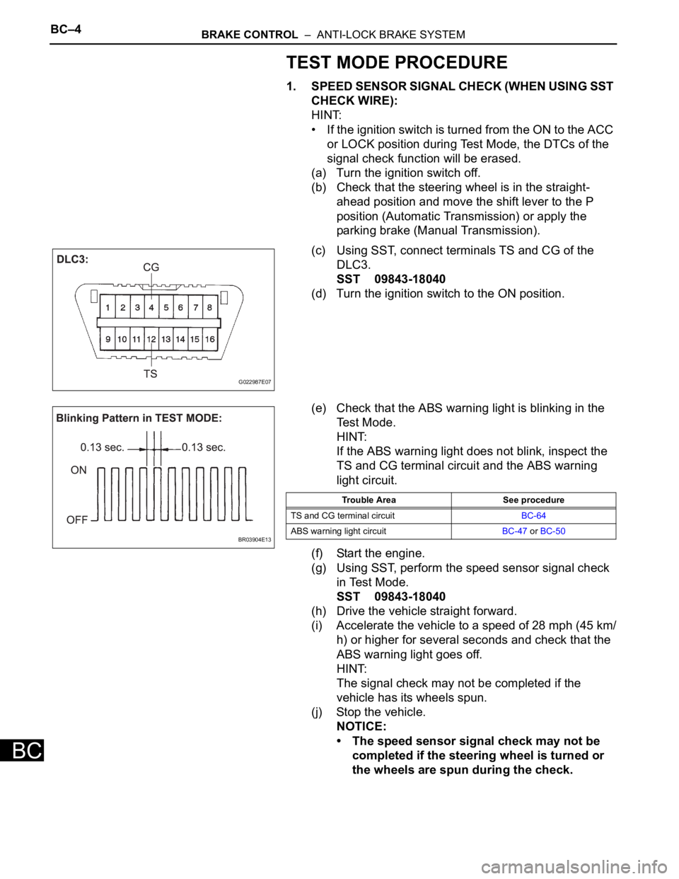
(c) Using SST, connect terminals TS and CG of the
DLC3.
SST 09843-18040
(d) Turn the ignition switch to the ON position.
(e) Check that the ABS warning light is blinking in the
Test Mode.
HINT:
If the ABS warning light does not blink, inspect the
TS and CG terminal circuit and the ABS warning
light circuit.
(f) Start the engine.
(g) Using SST, perform the speed sensor signal check
in Test Mode.
SST 09843-18040
(h) Drive the vehicle straight forward.
(i) Accelerate the vehicle to a speed of 28 mph (45 km/
h) or higher for several seconds and check that the
ABS warning light goes off.
HINT:
The signal check may not be completed if the
vehicle has its wheels spun.
(j) Stop the vehicle.
NOTICE:
• The speed sensor signal check may not be
completed if the steering wheel is turned or
the wheels are spun during the check.
G022987E07
BR03904E13
Trouble Area See procedure
TS and CG terminal circuitBC-64
ABS warning light circuitBC-47 or BC-50
Page 2903 of 3000

AC–14AIR CONDITIONING – AIR CONDITIONING SYSTEM (for Automatic Air Conditioning Sys-
tem)
AC
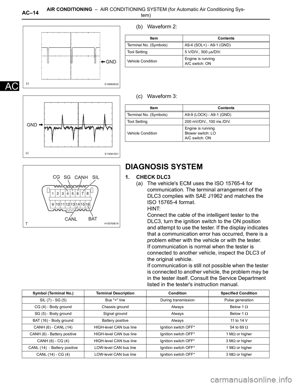
(b) Waveform 2:
(c) Waveform 3:
DIAGNOSIS SYSTEM
1. CHECK DLC3
(a) The vehicle's ECM uses the ISO 15765-4 for
communication. The terminal arrangement of the
DLC3 complies with SAE J1962 and matches the
ISO 15765-4 format.
HINT:
Connect the cable of the intelligent tester to the
DLC3, turn the ignition switch to the ON position
and attempt to use the tester. If the display indicates
that a communication error has occurred, there is a
problem either with the vehicle or with the tester.
If communication is normal when the tester is
connected to another vehicle, inspect the DLC3 of
the original vehicle.
If communication is still not possible when the tester
is connected to another vehicle, the problem may be
in the tester itself. Consult the Service Department
listed in the tester's instruction manual.
E106664E02
Item Contents
Terminal No. (Symbols) A9-4 (SOL+) - A9-1 (GND)
Tool Setting 5 V/DIV., 500
s/DIV.
Vehicle ConditionEngine is running
A/C switch: ON
E116941E01
Item Contents
Terminal No. (Symbols) A9-9 (LOCK) - A9-1 (GND)
Tool Setting 200 mV/DIV., 100 ms./DIV.
Vehicle ConditionEngine is running
Blower switch: LO
A/C switch: ON
H100769E16
Symbol (Terminal No.) Terminal Description Condition Specified Condition
SIL (7) - SG (5) Bus "+" line During transmission Pulse generation
CG (4) - Body ground Chassis ground Always Below 1
SG (5) - Body ground Signal ground Always Below 1
BAT (16) - Body ground Battery positive Always 11 to 14 V
CANH (6) - CANL (14) HIGH-level CAN bus line Ignition switch OFF*54 to 69
CANH (6) - Battery positive HIGH-level CAN bus line Ignition switch OFF* 1 M or higher
CANH (6) - CG (4) HIGH-level CAN bus line Ignition switch OFF* 3 M
or higher
CANL (14) - Battery positive LOW-level CAN bus line Ignition switch OFF* 1 M
or higher
CANL (14) - CG (4) LOW-level CAN bus line Ignition switch OFF* 3 M
or higher
Page 2927 of 3000

AIR CONDITIONING – AIR CONDITIONING UNITAC–183
AC
11. DISCONNECT HEATER WATER OUTLET HOSE A
(FROM HEATER UNIT)
(a) Using pliers, grip the claws of the clip and slide the
clip to disconnect the heater water outlet hose A
(from heater unit).
12. REMOVE HEATER WATER INLET HOSE A
HINT:
Disconnection of the heater water inlet hose A is the
same way as the heater water outlet hose A (from heater
unit).
13. REMOVE INSTRUMENT PANEL SUB-ASSEMBLY
WITH PASSENGER AIRBAG ASSEMBLY
HINT:
Refer to the instructions for removal of the instrument
panel sub-assembly with passenger airbag assembly
(See page IP-5).
14. REMOVE SPIRAL CABLE (See page RS-434)
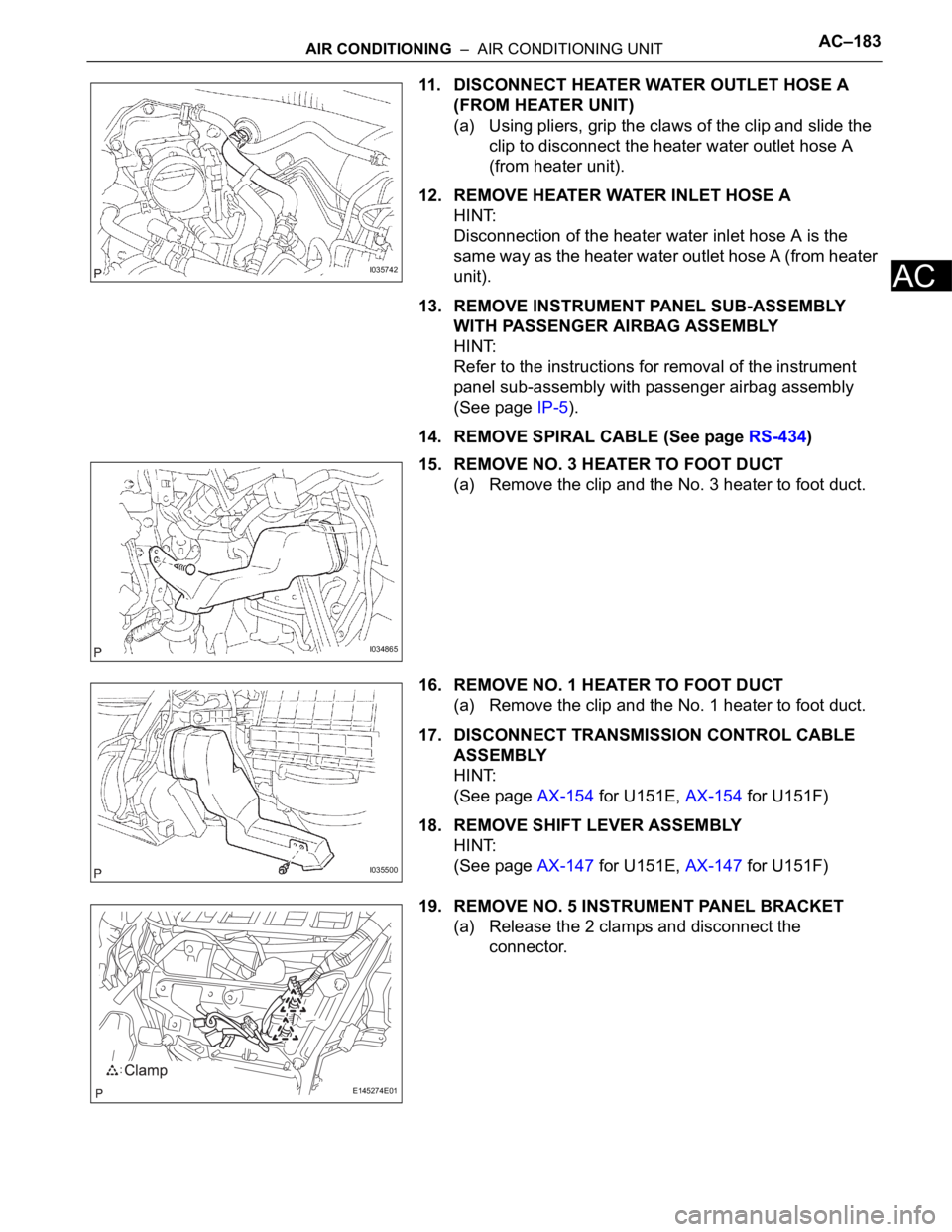
15. REMOVE NO. 3 HEATER TO FOOT DUCT
(a) Remove the clip and the No. 3 heater to foot duct.
16. REMOVE NO. 1 HEATER TO FOOT DUCT
(a) Remove the clip and the No. 1 heater to foot duct.
17. DISCONNECT TRANSMISSION CONTROL CABLE
ASSEMBLY
HINT:
(See page AX-154 for U151E, AX-154 for U151F)
18. REMOVE SHIFT LEVER ASSEMBLY
HINT:
(See page AX-147 for U151E, AX-147 for U151F)
19. REMOVE NO. 5 INSTRUMENT PANEL BRACKET
(a) Release the 2 clamps and disconnect the
connector.
I035742
I034865
I035500
E145274E01