2007 TOYOTA SIENNA Fuel System
[x] Cancel search: Fuel SystemPage 1406 of 3000

AX–36U151E AUTOMATIC TRANSAXLE – AUTOMATIC TRANSAXLE SYSTEM
AX
FAIL-SAFE CHART
1. FAIL-SAFE
This function minimizes the loss of the ECT functions
when any malfunction occurs in a sensor or solenoid.
(a) ATF (Automatic Transmission Fluid) temperature
sensor:
When the ATF temperature sensor has a
malfunction, 5th upshift is prohibited.
(b) Counter gear speed sensor NC (Speed sensor NC):
When the counter gear speed sensor has a
malfunction, 5th upshift is prohibited.
(c) Shift solenoid valve DSL:
When the solenoid valve DSL has a malfunction, the
current to the solenoid valve is stopped.
This stops lock-up control, then fuel economy
decreases.
(d) Shift solenoid valve SL1, SL2, SL3 and S4:
Fail safe function:
If either of the shift solenoid valve circuits develops
an open or short, the ECM turns the other shift
solenoid "ON" and "OFF" in order to shift into the
gear positions shown in the table below.
Manual shifting as shown in the following table must
be done (In case of a short circuit, the ECM stops
sending the current to the short circuited solenoid).
Even if starting the engine in the fail-safe mode, the
gear position remains in the same position.
HINT:
FL: Flex Lock-up
NormalSolenoid ValveSL1 ON OFF ON OFF OFF
SL2 ON ON OFF FL FL
SL3 OFF OFF OFF ON ON
S4 OFF OFF OFF OFF ON
Gear Position 1st 2nd 3rd 4th 5th
SL1
Malfunction
(During driving
at 1st or 2nd)Solenoid ValveSL1 OFF
SL2 ON ON OFF to ON FL to ON FL to ON
SL3 OFF OFF OFF ON to OFF ON to OFF
S4 OFF OFF OFF OFF ON to OFF
Gear Position 1st to 2nd 2nd 3rd to 2nd 4th to 2nd 5th to 2nd
SL1
Malfunction
(During driving
at 3rd)Solenoid ValveSL1 OFF
SL2 ON to FL ON to FL OFF to FL FL FL
SL3 OFF OFF OFF ON to OFF ON to OFF
S4 OFF to ON OFF to ON OFF to ON OFF to ON ON
Gear Position 1st to 4th 2nd to 4th 3rd to 4th 4th 5th to 4th
SL1
Malfunction
(During driving
at 4th or 5th)Solenoid ValveSL1 OFF
SL2 ON to FL ON to FL OFF to FL FL FL
SL3 OFF to ON OFF to ON OFF to ON ON ON
S4 OFF OFF OFF OFF ON
Gear Position 1st to 4th 2nd to 4th 3rd to 4th 4th 5th to 4th
Page 1543 of 3000

AX–30U151E AUTOMATIC TRANSAXLE – AUTOMATIC TRANSAXLE SYSTEM
AX
(g) Freeze frame data records the engine conditions
(fuel system, calculated load, engine coolant
temperature, fuel trim, engine speed, vehicle speed,
etc.) when a malfunction is detected. When
troubleshooting, freeze frame data can help
determine if the vehicle was running or stopped, if
the engine was warmed up or not, if the air/fuel ratio
was Lean or Rich, and other data from the time the
malfunction occurred.
(h) The intelligent tester records freeze frame data in
five different instance: 1) 3 times before the DTC is
set, 2) once when the DTC is set, and 3) once after
the DTC is set. These data can be used to simulate
the vehicle's condition around the time when the
malfunction occurred. The data may help find the
cause of the malfunction, or judge if the DTC is
being caused by temporary malfunction or not.
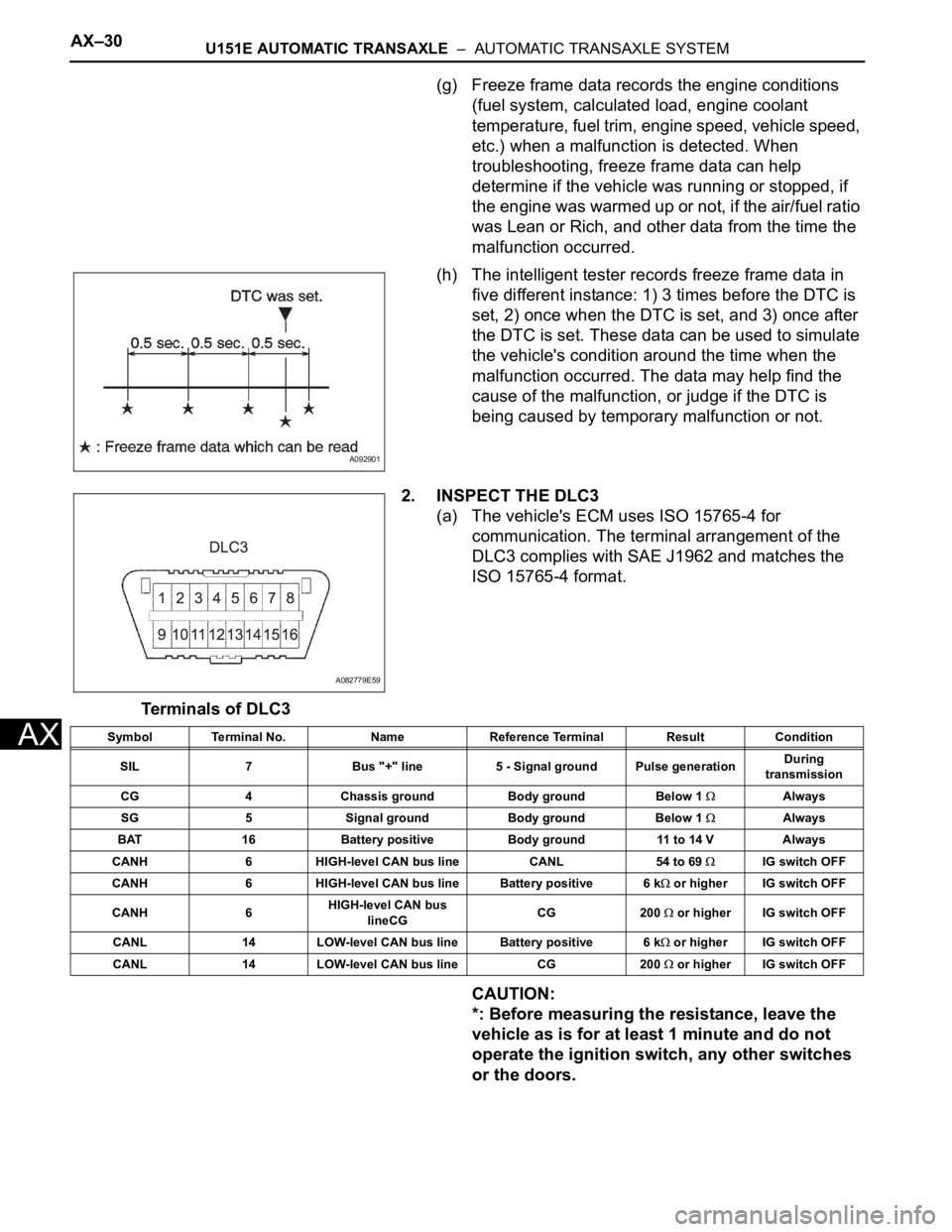
2. INSPECT THE DLC3
(a) The vehicle's ECM uses ISO 15765-4 for
communication. The terminal arrangement of the
DLC3 complies with SAE J1962 and matches the
ISO 15765-4 format.
Terminals of DLC3
CAUTION:
*: Before measuring the resistance, leave the
vehicle as is for at least 1 minute and do not
operate the ignition switch, any other switches
or the doors.
A092901
A082779E59
Symbol Terminal No. Name Reference Terminal Result Condition
SIL 7 Bus "+" line 5 - Signal ground Pulse generationDuring
transmission
CG 4 Chassis ground Body ground Below 1
Always
SG 5 Signal ground Body ground Below 1
Always
BAT 16 Battery positive Body ground 11 to 14 V Always
CANH 6 HIGH-level CAN bus line CANL 54 to 69
IG switch OFF
CANH 6 HIGH-level CAN bus line Battery positive 6 k
or higher IG switch OFF
CANH 6HIGH-level CAN bus
lineCGCG 200
or higher IG switch OFF
CANL 14 LOW-level CAN bus line Battery positive 6 k
or higher IG switch OFF
CANL 14 LOW-level CAN bus line CG 200
or higher IG switch OFF
Page 1686 of 3000

AX–6U151F AUTOMATIC TRANSAXLE – AUTOMATIC TRANSAXLE SYSTEM
AX
SYSTEM DESCRIPTION
1. SYSTEM DESCRIPTION
(a) The ECT (Electronic controlled automatic
transmission/transaxle) is an automatic
transmission/transaxle that electronically controls
shift timing using the ECM. The ECM detects
electrical signals that indicate engine and driving
conditions, and controls the shift point, based on
driver habits and road conditions. As a result, fuel
efficiency and power transmission performance are
improved.
Shift shock has been reduced by controlling the
engine and transmission simultaneously.
In addition, the ECT has features such as follows:
• Diagnostic function.
• Fail-safe function when a malfunction occurs.
Page 1712 of 3000

AX–36U151F AUTOMATIC TRANSAXLE – AUTOMATIC TRANSAXLE SYSTEM
AX
FAIL-SAFE CHART
1. FAIL-SAFE
This function minimizes the loss of the ECT functions
when any malfunction occurs in a sensor or solenoid.
(a) ATF (Automatic Transmission Fluid) temperature
sensor:
When the ATF temperature sensor has a
malfunction, 5th upshift is prohibited.
(b) Counter gear speed sensor NC (Speed sensor NC):
When the counter gear speed sensor has a
malfunction, 5th upshift is prohibited.
(c) Shift solenoid valve DSL:
When the solenoid valve DSL has a malfunction, the
current to the solenoid valve is stopped.
This stops lock-up control, then fuel economy
decreases.
(d) Shift solenoid valve SL1, SL2, SL3 and S4:
Fail safe function:
If either of the shift solenoid valve circuits develops
an open or short, the ECM turns the other shift
solenoid "ON" and "OFF" in order to shift into the
gear positions shown in the table below.
Manual shifting as shown in the following table must
be done (In case of a short circuit, the ECM stops
sending the current to the short circuited solenoid).
Even if starting the engine in the fail-safe mode, the
gear position remains in the same position.
HINT:
FL: Flex Lock-up
NormalSolenoid ValveSL1 ON OFF ON OFF OFF
SL2 ON ON OFF FL FL
SL3 OFF OFF OFF ON ON
S4 OFF OFF OFF OFF ON
Gear Position 1st 2nd 3rd 4th 5th
SL1
Malfunction
(During driving
at 1st or 2nd)Solenoid ValveSL1 OFF
SL2 ON ON OFF to ON FL to ON FL to ON
SL3 OFF OFF OFF ON to OFF ON to OFF
S4 OFF OFF OFF OFF ON to OFF
Gear Position 1st to 2nd 2nd 3rd to 2nd 4th to 2nd 5th to 2nd
SL1
Malfunction
(During driving
at 3rd)Solenoid ValveSL1 OFF
SL2 ON to FL ON to FL OFF to FL FL FL
SL3 OFF OFF OFF ON to OFF ON to OFF
S4 OFF to ON OFF to ON OFF to ON OFF to ON ON
Gear Position 1st to 4th 2nd to 4th 3rd to 4th 4th 5th to 4th
SL1
Malfunction
(During driving
at 4th or 5th)Solenoid ValveSL1 OFF
SL2 ON to FL ON to FL OFF to FL FL FL
SL3 OFF to ON OFF to ON OFF to ON ON ON
S4 OFF OFF OFF OFF ON
Gear Position 1st to 4th 2nd to 4th 3rd to 4th 4th 5th to 4th
Page 1846 of 3000

AX–30U151F AUTOMATIC TRANSAXLE – AUTOMATIC TRANSAXLE SYSTEM
AX
(g) Freeze frame data records the engine conditions
(fuel system, calculated load, engine coolant
temperature, fuel trim, engine speed, vehicle speed,
etc.) when a malfunction is detected. When
troubleshooting, freeze frame data can help
determine if the vehicle was running or stopped, if
the engine was warmed up or not, if the air/fuel ratio
was Lean or Rich, and other data from the time the
malfunction occurred.
(h) The intelligent tester records freeze frame data in
five different instance: 1) 3 times before the DTC is
set, 2) once when the DTC is set, and 3) once after
the DTC is set. These data can be used to simulate
the vehicle's condition around the time when the
malfunction occurred. The data may help find the
cause of the malfunction, or judge if the DTC is
being caused by temporary malfunction or not.
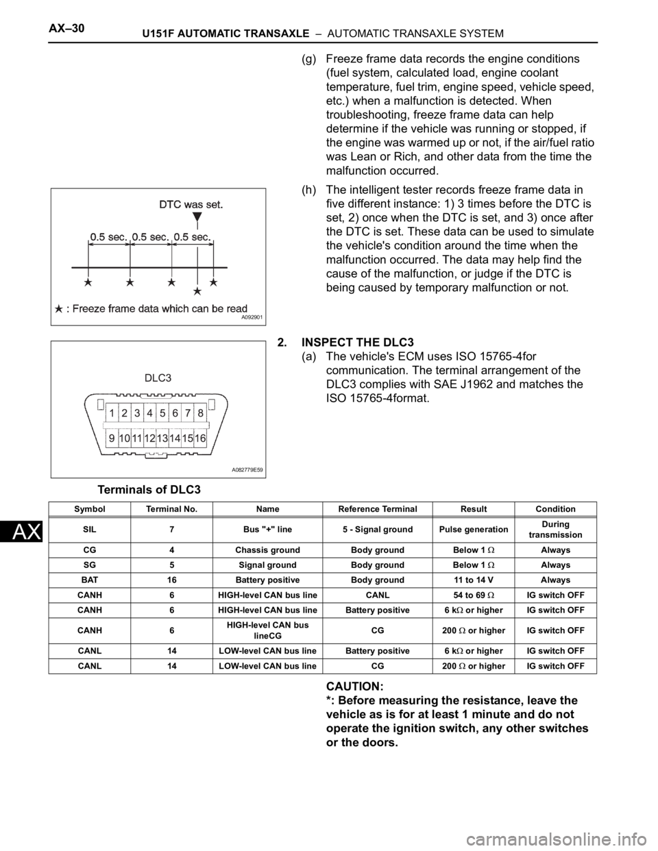
2. INSPECT THE DLC3
(a) The vehicle's ECM uses ISO 15765-4for
communication. The terminal arrangement of the
DLC3 complies with SAE J1962 and matches the
ISO 15765-4format.
Terminals of DLC3
CAUTION:
*: Before measuring the resistance, leave the
vehicle as is for at least 1 minute and do not
operate the ignition switch, any other switches
or the doors.
A092901
A082779E59
Symbol Terminal No. Name Reference Terminal Result Condition
SIL 7 Bus "+" line 5 - Signal ground Pulse generationDuring
transmission
CG 4 Chassis ground Body ground Below 1
Always
SG 5 Signal ground Body ground Below 1
Always
BAT 16 Battery positive Body ground 11 to 14 V Always
CANH 6 HIGH-level CAN bus line CANL 54 to 69
IG switch OFF
CANH 6 HIGH-level CAN bus line Battery positive 6 k
or higher IG switch OFF
CANH 6HIGH-level CAN bus
lineCGCG 200
or higher IG switch OFF
CANL 14 LOW-level CAN bus line Battery positive 6 k
or higher IG switch OFF
CANL 14 LOW-level CAN bus line CG 200
or higher IG switch OFF
Page 2231 of 3000

SP–48SUSPENSION – REAR COIL SPRING
SP
(b) Fully tighten the nut.
Torque: 115 N*m (1,173 kgf*cm, 85 ft.*lbf)
21. FULLY TIGHTEN SHOCK ABSORBER ASSEMBLY
REAR RH
HINT:
Fully tighten the RH side by same procedures as the LH
side.
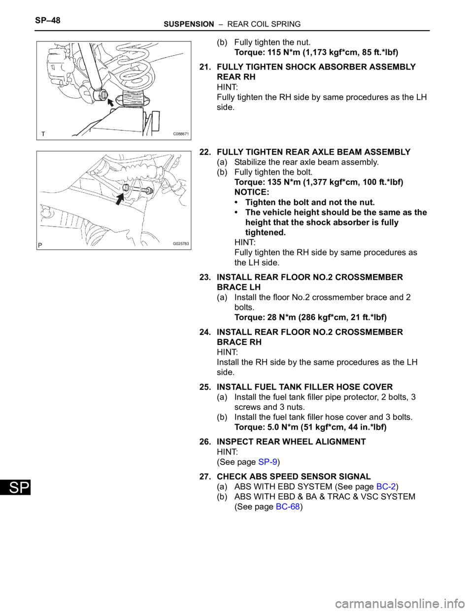
22. FULLY TIGHTEN REAR AXLE BEAM ASSEMBLY
(a) Stabilize the rear axle beam assembly.
(b) Fully tighten the bolt.
Torque: 135 N*m (1,377 kgf*cm, 100 ft.*lbf)
NOTICE:
• Tighten the bolt and not the nut.
• The vehicle height should be the same as the
height that the shock absorber is fully
tightened.
HINT:
Fully tighten the RH side by same procedures as
the LH side.
23. INSTALL REAR FLOOR NO.2 CROSSMEMBER
BRACE LH
(a) Install the floor No.2 crossmember brace and 2
bolts.
Torque: 28 N*m (286 kgf*cm, 21 ft.*lbf)
24. INSTALL REAR FLOOR NO.2 CROSSMEMBER
BRACE RH
HINT:
Install the RH side by the same procedures as the LH
side.
25. INSTALL FUEL TANK FILLER HOSE COVER
(a) Install the fuel tank filler pipe protector, 2 bolts, 3
screws and 3 nuts.
(b) Install the fuel tank filler hose cover and 3 bolts.
Torque: 5.0 N*m (51 kgf*cm, 44 in.*lbf)
26. INSPECT REAR WHEEL ALIGNMENT
HINT:
(See page SP-9)
27. CHECK ABS SPEED SENSOR SIGNAL
(a) ABS WITH EBD SYSTEM (See page BC-2)
(b) ABS WITH EBD & BA & TRAC & VSC SYSTEM
(See page BC-68)
C088671
G025783
Page 2247 of 3000

SUSPENSION – REAR AXLE BEAMSP–65
SP
45. INSTALL FUEL TANK FILLER HOSE COVER
HINT:
(See page SP-38)
46. INSPECT REAR WHEEL ALIGNMENT
HINT:
(See page SP-9)
47. CHECK ABS SPEED SENSOR SIGNAL
(a) ABS WITH EBD SYSTEM (See page BC-2)
(b) ABS WITH EBD & BA & TRAC & VSC SYSTEM
(See page BC-68)
Page 2992 of 3000

SUPPLEMENTAL RESTRAINT SYSTEM – AIRBAG SYSTEMRS–15
RS
SYSTEM DESCRIPTION
1. GENERAL
(a) In conjunction with impact absorbing structure for a
frontal collision, the SRS (Supplemental Restraint
System) driver airbag and front passenger airbag
were designed to supplement seat belts in the event
of a frontal collision in order to help reduce shock to
the head and chest. This system is a 3-sensor type
airbag system to detect the impact during a frontal
collision using the center airbag sensor assembly
and front airbag sensors. It also operates the airbag
system and seat belt pretensioner.
(b) In order to detect the extent of the collision during
the initial stages of the collision in further detail, the
front airbag sensors have been changed from
mechanical type to electrical type deceleration
sensors. Accordingly, the deployment of the driver
airbag and front passenger airbag is controlled in
two stages according to the severity of the impact.
(c) In conjunction with impact absorbing structure for a
side collision, the front seat side airbag and curtain
shield airbag were designed to help reduce shock to
the driver, front passenger, and rear outer
passengers in the event of a side collision or
rollover.
(d) RSCA (Roll Sensing of Curtain Shield Airbags) is
used in order to deploy the curtain shield airbags
and the seat belt pretensioner for the driver and
front passenger, in the event that the vehicle rolls
over.
(e) The curtain shield airbag that helps reduce shock to
the front and rear seat occupants with a single
curtain shield airbag has been adopted. In
conjunction with this system, the side airbag
sensors have been installed at the bottom of the
center pillars and the rear airbag sensors have been
installed at the bottom of the rear pillars
respectively.
(f) In this system, a front side collision is detected by
the side airbag sensors in order to deploy the front
seat side airbag and curtain shield airbag. A rear
side collision is detected by the rear airbag sensors
and the center airbag sensor assembly in order to
deploy the curtain shield airbag.
(g) The center airbag sensor assembly sends the
airbag deployment signal to the ECM through BEAN
(Body Electronics Area Network) and CAN
(Controller Area Network) to operate the fuel pump
control.
(h) The center airbag sensor assembly sends the
airbag deployment signal to the body ECU via a
discrete line to operate collision door lock release
control.