Page 1021 of 3000

EM–622GR-FE ENGINE MECHANICAL – ENGINE ASSEMBLY
EM
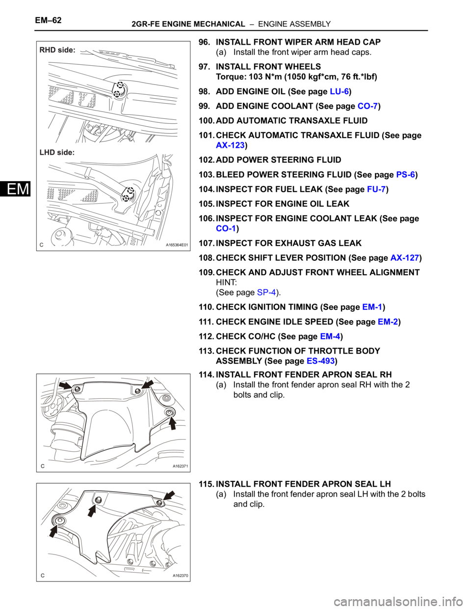
96. INSTALL FRONT WIPER ARM HEAD CAP
(a) Install the front wiper arm head caps.
97. INSTALL FRONT WHEELS
Torque: 103 N*m (1050 kgf*cm, 76 ft.*lbf)
98. ADD ENGINE OIL (See page LU-6)
99. ADD ENGINE COOLANT (See page CO-7)
100. ADD AUTOMATIC TRANSAXLE FLUID
101. CHECK AUTOMATIC TRANSAXLE FLUID (See page
AX-123)
102. ADD POWER STEERING FLUID
103. BLEED POWER STEERING FLUID (See page PS-6)
104. INSPECT FOR FUEL LEAK (See page FU-7)
105. INSPECT FOR ENGINE OIL LEAK
106. INSPECT FOR ENGINE COOLANT LEAK (See page
CO-1)
107. INSPECT FOR EXHAUST GAS LEAK
108. CHECK SHIFT LEVER POSITION (See page AX-127)
109. CHECK AND ADJUST FRONT WHEEL ALIGNMENT
HINT:
(See page SP-4).
110. CHECK IGNITION TIMING (See page EM-1)
111. CHECK ENGINE IDLE SPEED (See page EM-2)
112. CHECK CO/HC (See page EM-4)
113. CHECK FUNCTION OF THROTTLE BODY
ASSEMBLY (See page ES-493)
114. INSTALL FRONT FENDER APRON SEAL RH
(a) Install the front fender apron seal RH with the 2
bolts and clip.
115. INSTALL FRONT FENDER APRON SEAL LH
(a) Install the front fender apron seal LH with the 2 bolts
and clip.
A165364E01
A162371
A162370
Page 2209 of 3000
SUSPENSION – FRONT STABILIZER BAR (for 2WD)SP–31
SP
14. INSPECT STEERING WHEEL CENTER POINT
15. ADD POWER STEERING FLUID
16. BLEED POWER STEERING FLUID
HINT:
(See page SP-26)
17. CHECK POWER STEERING FLUID LEAKAGE
18. INSPECT AND ADJUST FRONT WHEEL ALIGNMENT
HINT:
(See page SP-4)
Page 2219 of 3000
SP–38SUSPENSION – FRONT STABILIZER BAR (for 4WD)
SP
13. INSTALL FRONT STABILIZER LINK ASSEMBLY LH
HINT:
(See page AH-4)
14. INSTALL FRONT STABILIZER LINK ASSEMBLY RH
HINT:
Install the RH side by the same procedures as the LH
side.
15. INSTALL FRONT WHEELS
16. INSPECT CENTER FRONT WHEEL
17. INSPECT STEERING WHEEL CENTER POINT
18. ADD POWER STEERING FLUID
19. BLEED POWER STEERING FLUID
HINT:
(See page PS-6)
20. CHECK POWER STEERING FLUID LEAKAGE
21. INSPECT AND ADJUST FRONT WHEEL ALIGNMENT
HINT:
(See page SP-4)
Page 2223 of 3000
SP–38SUSPENSION – FRONT STABILIZER BAR (for 4WD)
SP
13. INSTALL FRONT STABILIZER LINK ASSEMBLY LH
HINT:
(See page AH-4)
14. INSTALL FRONT STABILIZER LINK ASSEMBLY RH
HINT:
Install the RH side by the same procedures as the LH
side.
15. INSTALL FRONT WHEELS
16. INSPECT CENTER FRONT WHEEL
17. INSPECT STEERING WHEEL CENTER POINT
18. ADD POWER STEERING FLUID
19. BLEED POWER STEERING FLUID
HINT:
(See page PS-6)
20. CHECK POWER STEERING FLUID LEAKAGE
21. INSPECT AND ADJUST FRONT WHEEL ALIGNMENT
HINT:
(See page SP-4)
Page 2678 of 3000

SR–2STEERING COLUMN – STEERING SYSTEM
SR
PROBLEM SYMPTOMS TABLE
HINT:
Use the table below to help determine the cause of the
problem. Likely causes of the problem are indicated in
descending order. Check each suspected area in order.
Repair or replace the faulty parts or perform adjustments as
necessary.
STEERING SYSTEM
ON-VEHICLE INSPECTION
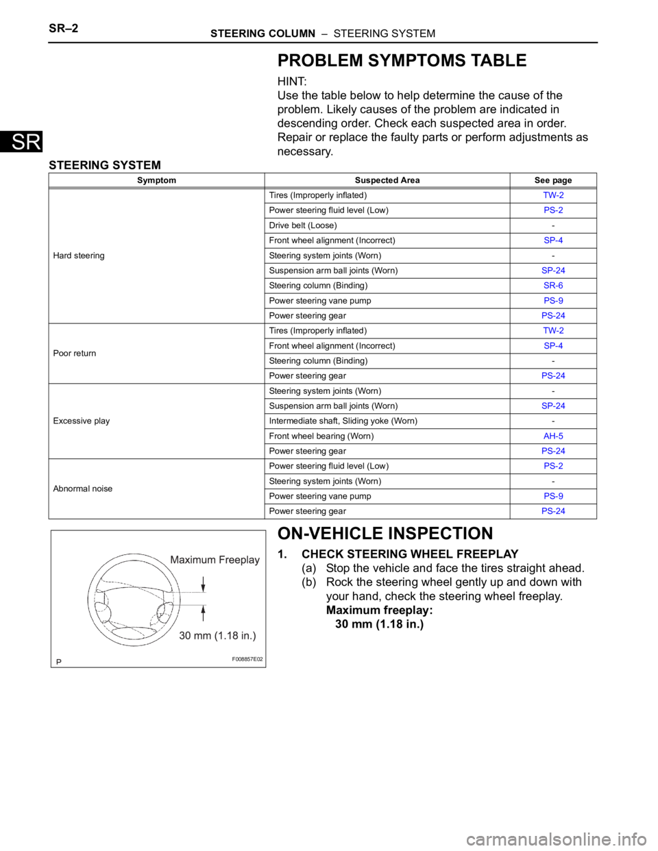
1. CHECK STEERING WHEEL FREEPLAY
(a) Stop the vehicle and face the tires straight ahead.
(b) Rock the steering wheel gently up and down with
your hand, check the steering wheel freeplay.
Maximum freeplay:
30 mm (1.18 in.)
Symptom Suspected Area See page
Hard steeringTires (Improperly inflated)TW-2
Power steering fluid level (Low)PS-2
Drive belt (Loose) -
Front wheel alignment (Incorrect)SP-4
Steering system joints (Worn) -
Suspension arm ball joints (Worn)SP-24
Steering column (Binding)SR-6
Power steering vane pumpPS-9
Power steering gearPS-24
Poor returnTires (Improperly inflated)TW-2
Front wheel alignment (Incorrect)SP-4
Steering column (Binding) -
Power steering gearPS-24
Excessive playSteering system joints (Worn) -
Suspension arm ball joints (Worn)SP-24
Intermediate shaft, Sliding yoke (Worn) -
Front wheel bearing (Worn)AH-5
Power steering gearPS-24
Abnormal noisePower steering fluid level (Low)PS-2
Steering system joints (Worn) -
Power steering vane pumpPS-9
Power steering gearPS-24
F008857E02
Page 2686 of 3000

POWER STEERING – VANE PUMPPS–15
PS
REASSEMBLY
NOTICE:
Before installation, coat the parts indicated by arrows
with power steering fluid (See page PS-7).
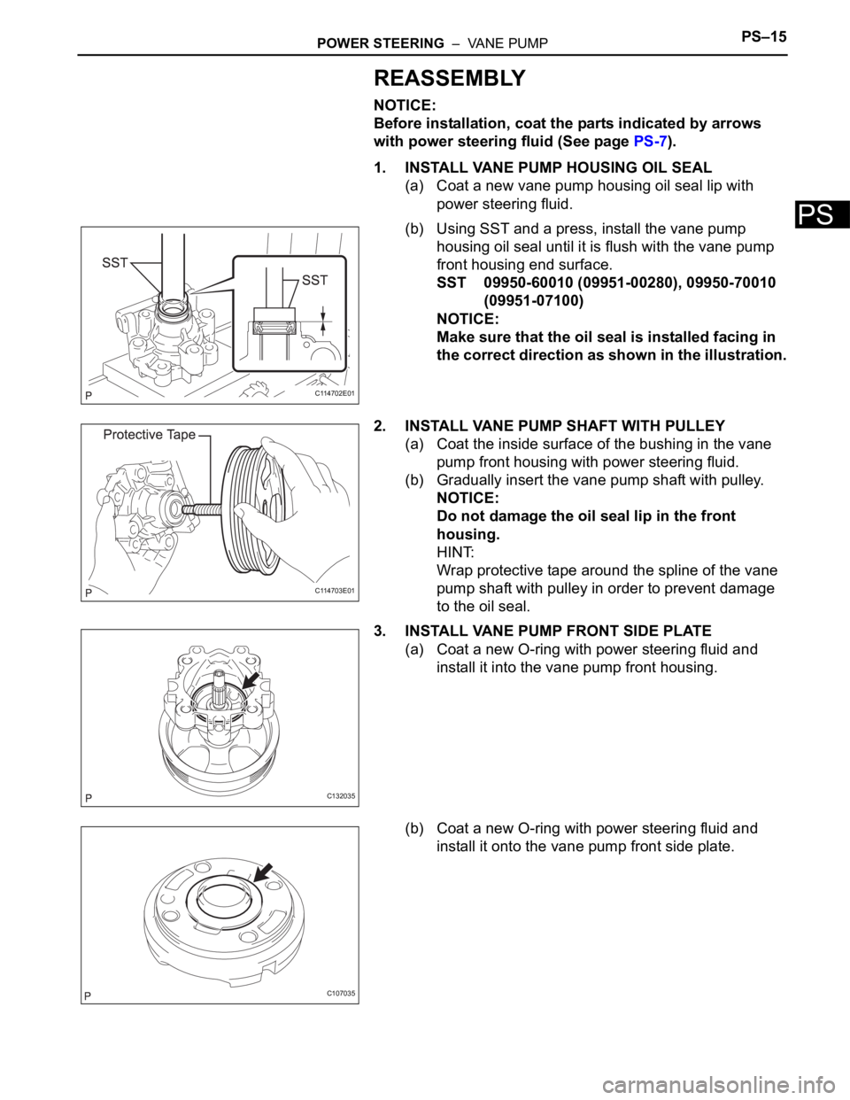
1. INSTALL VANE PUMP HOUSING OIL SEAL
(a) Coat a new vane pump housing oil seal lip with
power steering fluid.
(b) Using SST and a press, install the vane pump
housing oil seal until it is flush with the vane pump
front housing end surface.
SST 09950-60010 (09951-00280), 09950-70010
(09951-07100)
NOTICE:
Make sure that the oil seal is installed facing in
the correct direction as shown in the illustration.
2. INSTALL VANE PUMP SHAFT WITH PULLEY
(a) Coat the inside surface of the bushing in the vane
pump front housing with power steering fluid.
(b) Gradually insert the vane pump shaft with pulley.
NOTICE:
Do not damage the oil seal lip in the front
housing.
HINT:
Wrap protective tape around the spline of the vane
pump shaft with pulley in order to prevent damage
to the oil seal.
3. INSTALL VANE PUMP FRONT SIDE PLATE
(a) Coat a new O-ring with power steering fluid and
install it into the vane pump front housing.
(b) Coat a new O-ring with power steering fluid and
install it onto the vane pump front side plate.
C114702E01
C114703E01
C132035
C107035
Page 2687 of 3000
PS–16POWER STEERING – VANE PUMP
PS
(c) Align the notch of the vane pump front side plate
with that of the vane pump front housing, and install
the vane pump front side plate.
NOTICE:
Make sure that the vane pump front side plate is
installed facing in the correct direction.
4. INSTALL VANE PUMP CAM RING
(a) Align the notch of the cam ring with that of the vane
pump front side plate, and install the vane pump
cam ring with the inscribed mark facing upward.
NOTICE:
Make sure that the vane pump cam ring is
installed facing in the correct direction.
5. INSTALL VANE PUMP ROTOR
(a) Install the vane pump rotor.
HINT:
The vane pump rotor can be installed in both
directions.
(b) Coat the 10 vane pump plates with power steering
fluid.
C132040E01
C139139E01
C107038
Page 2688 of 3000
POWER STEERING – VANE PUMPPS–17
PS
(c) Install the vane pump plates with the round end
facing outward.
NOTICE:
Make sure that the vane pump plates are
installed facing in the correct direction.
6. INSTALL VANE PUMP SHAFT SNAP RING
(a) Using a screwdriver and a snap ring expander,
install a new vane pump shaft snap ring onto the
vane pump shaft with pulley.
NOTICE:
Make sure that the vane pump shaft snap ring is
securely installed in the vane pump shaft
groove.
7. INSTALL VANE PUMP REAR HOUSING
(a) Coat a new O-ring with power steering fluid and
install it onto the vane pump rear housing.
(b) Align the straight pin of the vane pump rear housing
with the notches of the vane pump cam ring, vane
pump front side plate, and vane pump front housing.
C141370E01
D030336E01
C107040
C136780E01