Page 2731 of 3000
PS–20POWER STEERING – VANE PUMP
PS
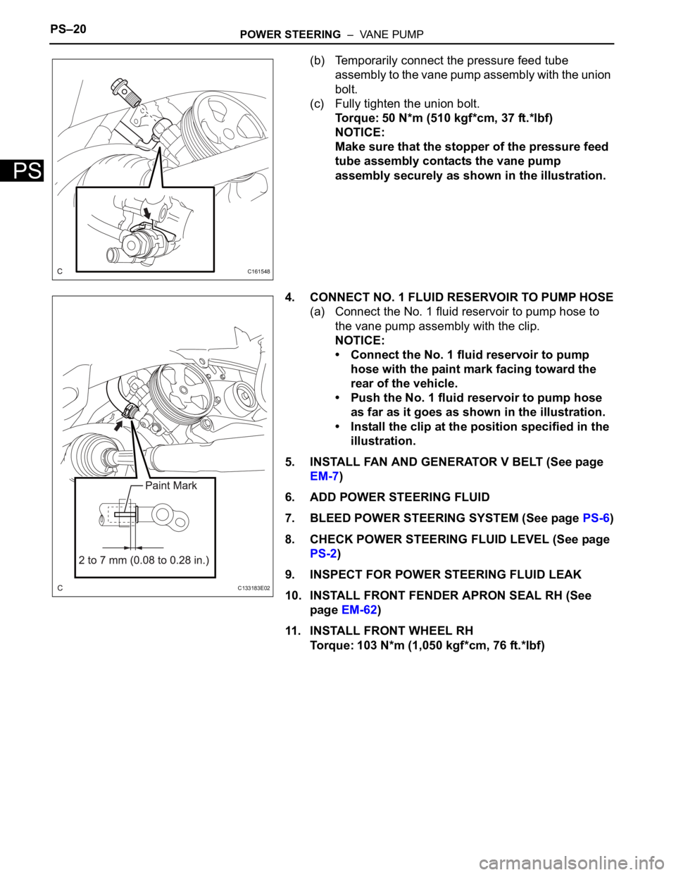
(b) Temporarily connect the pressure feed tube
assembly to the vane pump assembly with the union
bolt.
(c) Fully tighten the union bolt.
Torque: 50 N*m (510 kgf*cm, 37 ft.*lbf)
NOTICE:
Make sure that the stopper of the pressure feed
tube assembly contacts the vane pump
assembly securely as shown in the illustration.
4. CONNECT NO. 1 FLUID RESERVOIR TO PUMP HOSE
(a) Connect the No. 1 fluid reservoir to pump hose to
the vane pump assembly with the clip.
NOTICE:
• Connect the No. 1 fluid reservoir to pump
hose with the paint mark facing toward the
rear of the vehicle.
• Push the No. 1 fluid reservoir to pump hose
as far as it goes as shown in the illustration.
• Install the clip at the position specified in the
illustration.
5. INSTALL FAN AND GENERATOR V BELT (See page
EM-7)
6. ADD POWER STEERING FLUID
7. BLEED POWER STEERING SYSTEM (See page PS-6)
8. CHECK POWER STEERING FLUID LEVEL (See page
PS-2)
9. INSPECT FOR POWER STEERING FLUID LEAK
10. INSTALL FRONT FENDER APRON SEAL RH (See
page EM-62)
11. INSTALL FRONT WHEEL RH
Torque: 103 N*m (1,050 kgf*cm, 76 ft.*lbf)
C161548
C133183E02
Page 2735 of 3000
PS–24POWER STEERING – RACK AND PINION POWER STEERING GEAR
PS
REMOVAL
NOTICE:
When installing, coat the parts indicated by the arrows
with power steering fluid or molybdenum disulfide
lithium base grease (See page PS-21).
1. INSPECT CENTER FRONT WHEEL
2. REMOVE FRONT WHEEL
3. SEPARATE TIE ROD ASSEMBLY LH
SST 09628-62011
4. SEPARATE TIE ROD ASSEMBLY RH
SST 09628-62011
HINT:
Perform the same procedure on the other side.
5. SEPARATE STEERING INTERMEDIATE SHAFT
ASSEMBLY
(a) Fix the steering wheel with the seat belt.
(b) Release the 3 springs and separate the dust cover.
(c) Place matchmarks on the intermediate shaft
assembly and power steering gear assembly.
(d) Remove the bolt and separate the intermediate
shaft assembly.
6. SEPARATE FRONT STABILIZER LINK ASSEMBLY LH
7. SEPARATE FRONT STABILIZER LINK ASSEMBLY
RH
HINT:
Perform the same procedure on the other side.
D030613
D030704E03
D029986E03
Page 2742 of 3000
POWER STEERING – RACK AND PINION POWER STEERING GEARPS–31
PS
20. REMOVE RACK STEERING PISTON RING
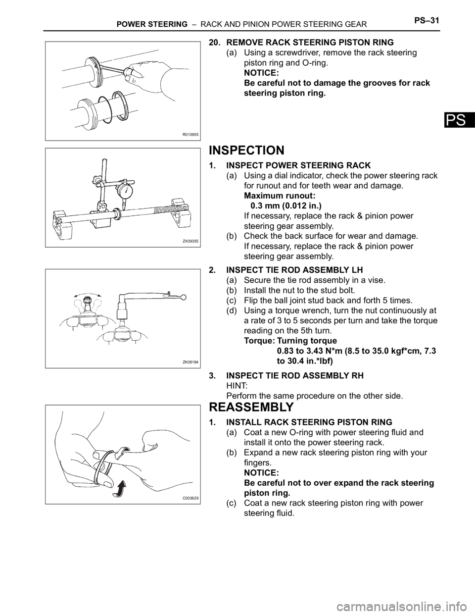
(a) Using a screwdriver, remove the rack steering
piston ring and O-ring.
NOTICE:
Be careful not to damage the grooves for rack
steering piston ring.
INSPECTION
1. INSPECT POWER STEERING RACK
(a) Using a dial indicator, check the power steering rack
for runout and for teeth wear and damage.
Maximum runout:
0.3 mm (0.012 in.)
If necessary, replace the rack & pinion power
steering gear assembly.
(b) Check the back surface for wear and damage.
If necessary, replace the rack & pinion power
steering gear assembly.
2. INSPECT TIE ROD ASSEMBLY LH
(a) Secure the tie rod assembly in a vise.
(b) Install the nut to the stud bolt.
(c) Flip the ball joint stud back and forth 5 times.
(d) Using a torque wrench, turn the nut continuously at
a rate of 3 to 5 seconds per turn and take the torque
reading on the 5th turn.
Torque: Turning torque
0.83 to 3.43 N*m (8.5 to 35.0 kgf*cm, 7.3
to 30.4 in.*lbf)
3. INSPECT TIE ROD ASSEMBLY RH
HINT:
Perform the same procedure on the other side.
REASSEMBLY
1. INSTALL RACK STEERING PISTON RING
(a) Coat a new O-ring with power steering fluid and
install it onto the power steering rack.
(b) Expand a new rack steering piston ring with your
fingers.
NOTICE:
Be careful not to over expand the rack steering
piston ring.
(c) Coat a new rack steering piston ring with power
steering fluid.
R010955
ZX09355
ZK08184
C003629
Page 2743 of 3000
PS–32POWER STEERING – RACK AND PINION POWER STEERING GEAR
PS
(d) Install the rack steering piston ring onto the power
steering rack, and settle it down with your fingers.
2. INSTALL POWER STEERING CYLINDER TUBE OIL
SEAL
(a) Coat a new cylinder tube oil seal lip with power
steering fluid.
(b) Using SST and a press, install the cylinder tube oil
seal.
SST 09950-60010 (09951-00420, 09951-00250,
09952-06010), 09950-70010 (09951-07360)
NOTICE:
• Make sure that the cylinder tube oil seal is
installed facing in the correct direction.
• Take care so that the cylinder tube oil seal
will not be reversed as you install it.
3. INSTALL POWER STEERING RACK
(a) Install SST onto the power steering rack.
SST 09631-33010
HINT:
If necessary, scrape the burrs off the power steering
rack teeth end and burnish.
(b) Coat the SST with power steering fluid.
(c) Install the power steering rack into the rack housing.
(d) Remove the SST.
N000401
F040545E06
W002101E12
Page 2744 of 3000
POWER STEERING – RACK AND PINION POWER STEERING GEARPS–33
PS
4. INSTALL POWER STEERING RACK BUSH
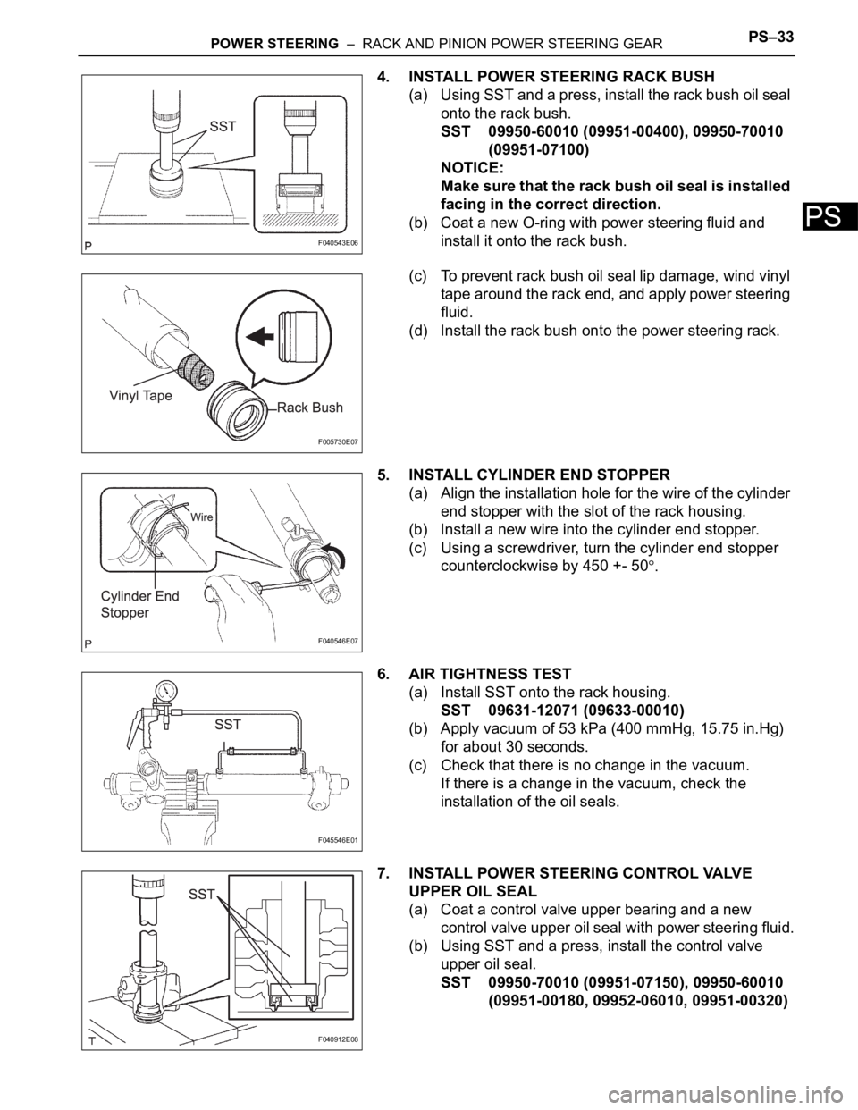
(a) Using SST and a press, install the rack bush oil seal
onto the rack bush.
SST 09950-60010 (09951-00400), 09950-70010
(09951-07100)
NOTICE:
Make sure that the rack bush oil seal is installed
facing in the correct direction.
(b) Coat a new O-ring with power steering fluid and
install it onto the rack bush.
(c) To prevent rack bush oil seal lip damage, wind vinyl
tape around the rack end, and apply power steering
fluid.
(d) Install the rack bush onto the power steering rack.
5. INSTALL CYLINDER END STOPPER
(a) Align the installation hole for the wire of the cylinder
end stopper with the slot of the rack housing.
(b) Install a new wire into the cylinder end stopper.
(c) Using a screwdriver, turn the cylinder end stopper
counterclockwise by 450 +- 50
.
6. AIR TIGHTNESS TEST
(a) Install SST onto the rack housing.
SST 09631-12071 (09633-00010)
(b) Apply vacuum of 53 kPa (400 mmHg, 15.75 in.Hg)
for about 30 seconds.
(c) Check that there is no change in the vacuum.
If there is a change in the vacuum, check the
installation of the oil seals.
7. INSTALL POWER STEERING CONTROL VALVE
UPPER OIL SEAL
(a) Coat a control valve upper bearing and a new
control valve upper oil seal with power steering fluid.
(b) Using SST and a press, install the control valve
upper oil seal.
SST 09950-70010 (09951-07150), 09950-60010
(09951-00180, 09952-06010, 09951-00320)
F040543E06
F005730E07
F040546E07
F045546E01
F040912E08
Page 2745 of 3000
PS–34POWER STEERING – RACK AND PINION POWER STEERING GEAR
PS
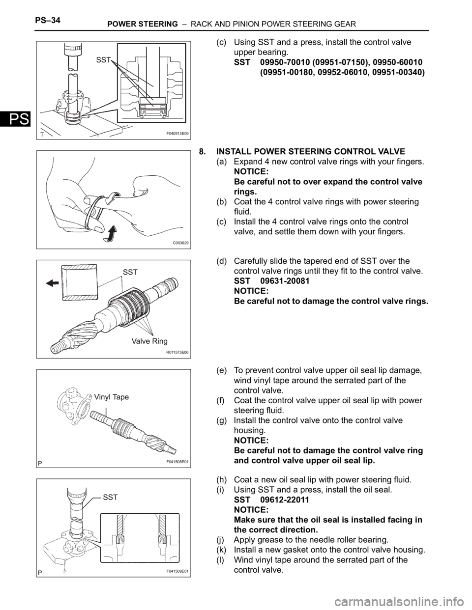
(c) Using SST and a press, install the control valve
upper bearing.
SST 09950-70010 (09951-07150), 09950-60010
(09951-00180, 09952-06010, 09951-00340)
8. INSTALL POWER STEERING CONTROL VALVE
(a) Expand 4 new control valve rings with your fingers.
NOTICE:
Be careful not to over expand the control valve
rings.
(b) Coat the 4 control valve rings with power steering
fluid.
(c) Install the 4 control valve rings onto the control
valve, and settle them down with your fingers.
(d) Carefully slide the tapered end of SST over the
control valve rings until they fit to the control valve.
SST 09631-20081
NOTICE:
Be careful not to damage the control valve rings.
(e) To prevent control valve upper oil seal lip damage,
wind vinyl tape around the serrated part of the
control valve.
(f) Coat the control valve upper oil seal lip with power
steering fluid.
(g) Install the control valve onto the control valve
housing.
NOTICE:
Be careful not to damage the control valve ring
and control valve upper oil seal lip.
(h) Coat a new oil seal lip with power steering fluid.
(i) Using SST and a press, install the oil seal.
SST 09612-22011
NOTICE:
Make sure that the oil seal is installed facing in
the correct direction.
(j) Apply grease to the needle roller bearing.
(k) Install a new gasket onto the control valve housing.
(l) Wind vinyl tape around the serrated part of the
control valve.
F040913E09
C003629
R011573E06
F041508E01
F041509E01
Page 2750 of 3000
POWER STEERING – RACK AND PINION POWER STEERING GEARPS–39
PS
HINT:
Perform the same procedure on the other side.
17. INSTALL STEERING RACK BOOT CLIP
(a) Using pliers, install the 2 rack boot clips.
18. INSTALL TIE ROD ASSEMBLY LH
(a) Screw the lock nut and tie rod assembly onto the
rack end sub-assembly until the matchmarks are
aligned.
HINT:
After adjusting toe-in, torque the lock nut.
19. INSTALL TIE ROD ASSEMBLY RH
HINT:
Perform the same procedure on the other side.
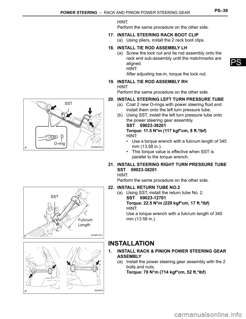
20. INSTALL STEERING LEFT TURN PRESSURE TUBE
(a) Coat 2 new O-rings with power steering fluid and
install them onto the left turn pressure tube.
(b) Using SST, install the left turn pressure tube onto
the power steering gear assembly.
SST 09023-38201
Torque: 11.5 N*m (117 kgf*cm, 8 ft.*lbf)
HINT:
• Use a torque wrench with a fulcrum length of 345
mm (13.58 in.).
• This torque value is effective when SST is
parallel to the torque wrench.
21. INSTALL STEERING RIGHT TURN PRESSURE TUBE
SST 09023-38201
HINT:
Perform the same procedure on the other side.
22. INSTALL RETURN TUBE NO.2
(a) Using SST, install the return tube No. 2.
SST 09023-12701
Torque: 22.5 N*m (229 kgf*cm, 17 ft.*lbf)
HINT:
Use a torque wrench with a fulcrum length of 345
mm (13.58 in.).
INSTALLATION
1. INSTALL RACK & PINION POWER STEERING GEAR
ASSEMBLY
(a) Install the power steering gear assembly with the 2
bolts and nuts.
Torque: 70 N*m (714 kgf*cm, 52 ft.*lbf)
D029981E02
D030601E01
D029979
Page 2752 of 3000
POWER STEERING – RACK AND PINION POWER STEERING GEARPS–41
PS
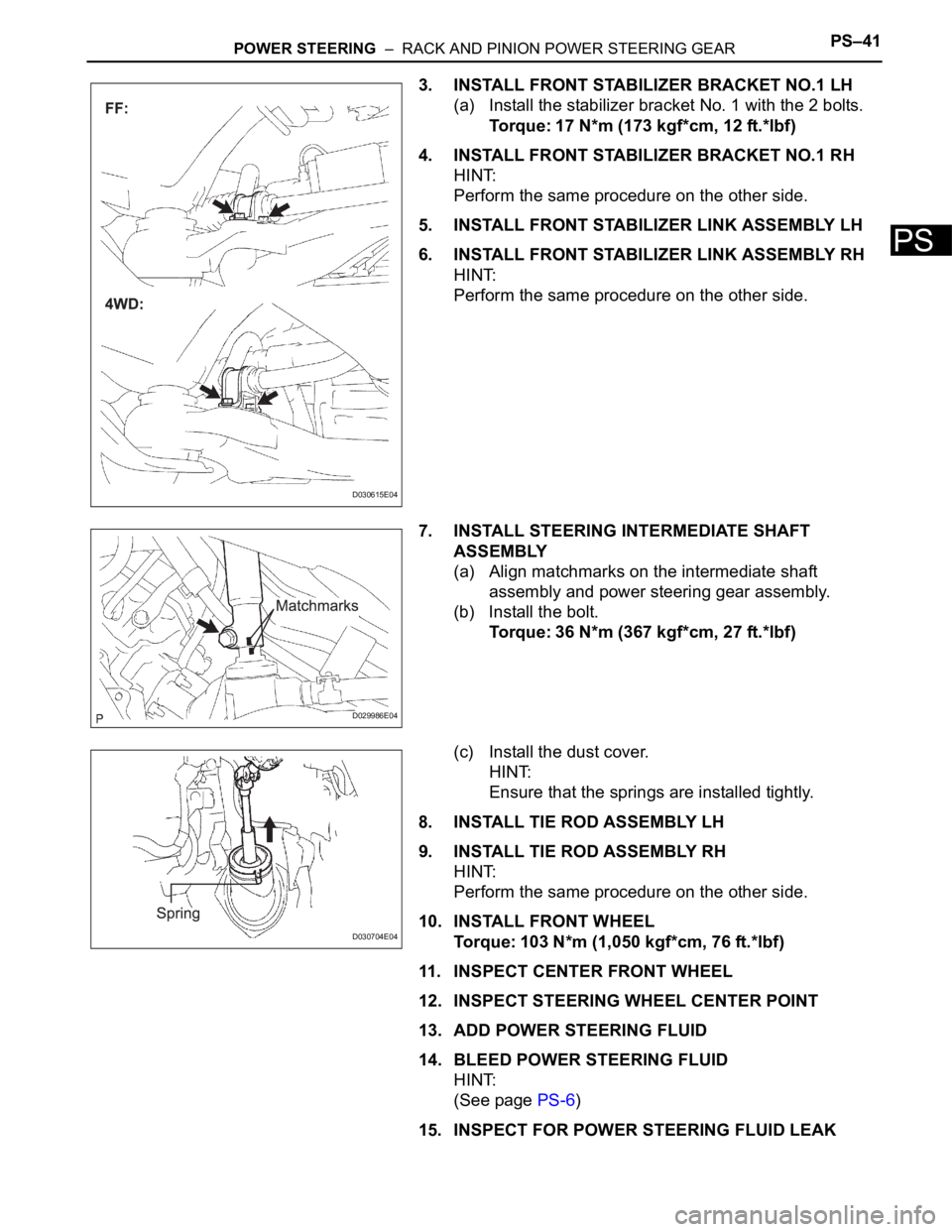
3. INSTALL FRONT STABILIZER BRACKET NO.1 LH
(a) Install the stabilizer bracket No. 1 with the 2 bolts.
Torque: 17 N*m (173 kgf*cm, 12 ft.*lbf)
4. INSTALL FRONT STABILIZER BRACKET NO.1 RH
HINT:
Perform the same procedure on the other side.
5. INSTALL FRONT STABILIZER LINK ASSEMBLY LH
6. INSTALL FRONT STABILIZER LINK ASSEMBLY RH
HINT:
Perform the same procedure on the other side.
7. INSTALL STEERING INTERMEDIATE SHAFT
ASSEMBLY
(a) Align matchmarks on the intermediate shaft
assembly and power steering gear assembly.
(b) Install the bolt.
Torque: 36 N*m (367 kgf*cm, 27 ft.*lbf)
(c) Install the dust cover.
HINT:
Ensure that the springs are installed tightly.
8. INSTALL TIE ROD ASSEMBLY LH
9. INSTALL TIE ROD ASSEMBLY RH
HINT:
Perform the same procedure on the other side.
10. INSTALL FRONT WHEEL
Torque: 103 N*m (1,050 kgf*cm, 76 ft.*lbf)
11. INSPECT CENTER FRONT WHEEL
12. INSPECT STEERING WHEEL CENTER POINT
13. ADD POWER STEERING FLUID
14. BLEED POWER STEERING FLUID
HINT:
(See page PS-6)
15. INSPECT FOR POWER STEERING FLUID LEAK
D030615E04
D029986E04
D030704E04