Page 1127 of 3000
FU–82GR-FE FUEL – FUEL SYSTEM
FU
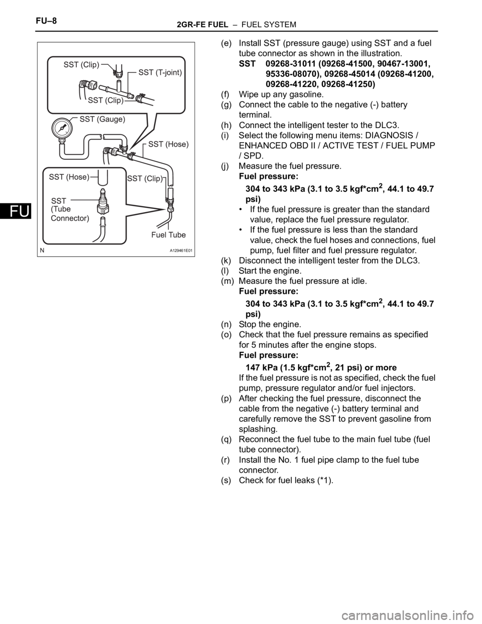
(e) Install SST (pressure gauge) using SST and a fuel
tube connector as shown in the illustration.
SST 09268-31011 (09268-41500, 90467-13001,
95336-08070), 09268-45014 (09268-41200,
09268-41220, 09268-41250)
(f) Wipe up any gasoline.
(g) Connect the cable to the negative (-) battery
terminal.
(h) Connect the intelligent tester to the DLC3.
(i) Select the following menu items: DIAGNOSIS /
ENHANCED OBD II / ACTIVE TEST / FUEL PUMP
/ SPD.
(j) Measure the fuel pressure.
Fuel pressure:
304 to 343 kPa (3.1 to 3.5 kgf*cm
2, 44.1 to 49.7
psi)
• If the fuel pressure is greater than the standard
value, replace the fuel pressure regulator.
• If the fuel pressure is less than the standard
value, check the fuel hoses and connections, fuel
pump, fuel filter and fuel pressure regulator.
(k) Disconnect the intelligent tester from the DLC3.
(l) Start the engine.
(m) Measure the fuel pressure at idle.
Fuel pressure:
304 to 343 kPa (3.1 to 3.5 kgf*cm
2, 44.1 to 49.7
psi)
(n) Stop the engine.
(o) Check that the fuel pressure remains as specified
for 5 minutes after the engine stops.
Fuel pressure:
147 kPa (1.5 kgf*cm
2, 21 psi) or more
If the fuel pressure is not as specified, check the fuel
pump, pressure regulator and/or fuel injectors.
(p) After checking the fuel pressure, disconnect the
cable from the negative (-) battery terminal and
carefully remove the SST to prevent gasoline from
splashing.
(q) Reconnect the fuel tube to the main fuel tube (fuel
tube connector).
(r) Install the No. 1 fuel pipe clamp to the fuel tube
connector.
(s) Check for fuel leaks (*1).
A129461E01
Page 1147 of 3000
FU–322GR-FE FUEL – FUEL PUMP
FU
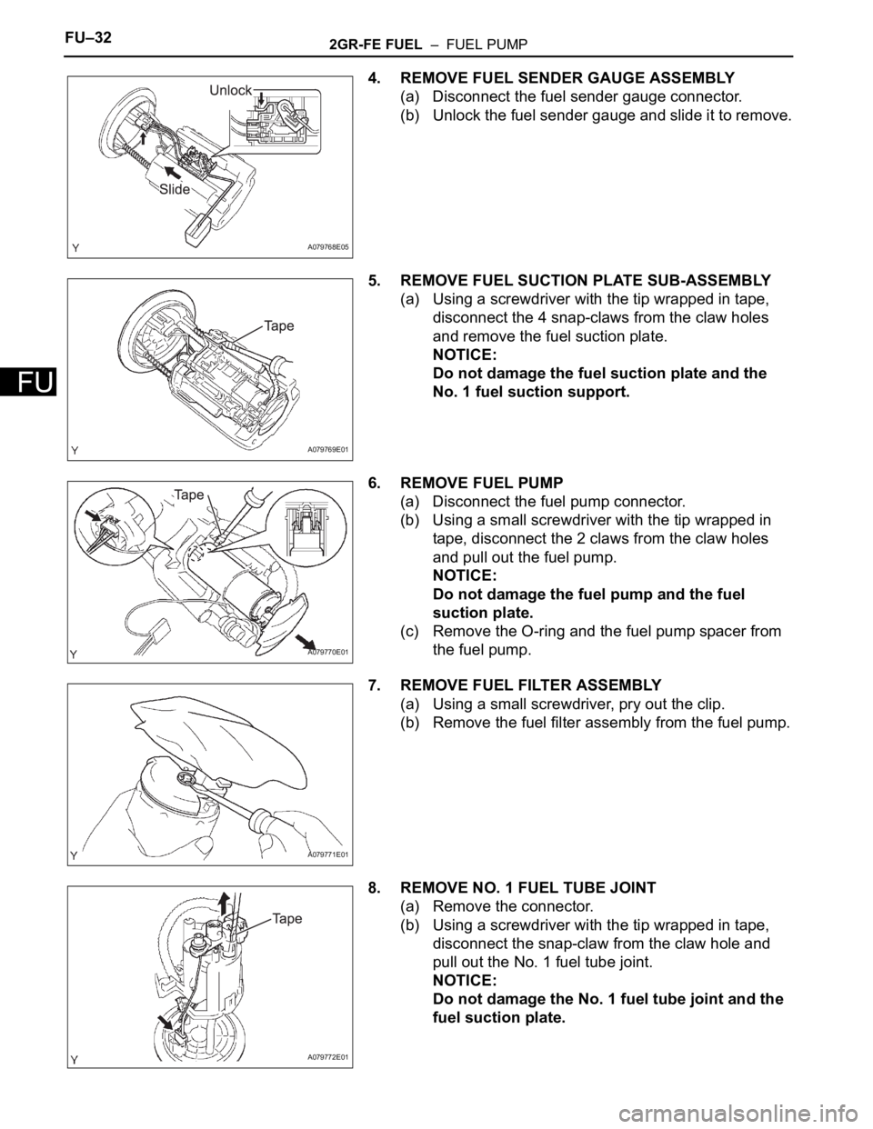
4. REMOVE FUEL SENDER GAUGE ASSEMBLY
(a) Disconnect the fuel sender gauge connector.
(b) Unlock the fuel sender gauge and slide it to remove.
5. REMOVE FUEL SUCTION PLATE SUB-ASSEMBLY
(a) Using a screwdriver with the tip wrapped in tape,
disconnect the 4 snap-claws from the claw holes
and remove the fuel suction plate.
NOTICE:
Do not damage the fuel suction plate and the
No. 1 fuel suction support.
6. REMOVE FUEL PUMP
(a) Disconnect the fuel pump connector.
(b) Using a small screwdriver with the tip wrapped in
tape, disconnect the 2 claws from the claw holes
and pull out the fuel pump.
NOTICE:
Do not damage the fuel pump and the fuel
suction plate.
(c) Remove the O-ring and the fuel pump spacer from
the fuel pump.
7. REMOVE FUEL FILTER ASSEMBLY
(a) Using a small screwdriver, pry out the clip.
(b) Remove the fuel filter assembly from the fuel pump.
8. REMOVE NO. 1 FUEL TUBE JOINT
(a) Remove the connector.
(b) Using a screwdriver with the tip wrapped in tape,
disconnect the snap-claw from the claw hole and
pull out the No. 1 fuel tube joint.
NOTICE:
Do not damage the No. 1 fuel tube joint and the
fuel suction plate.
A079768E05
A079769E01
A079770E01
A079771E01
A079772E01
Page 1150 of 3000
FU–322GR-FE FUEL – FUEL PUMP
FU
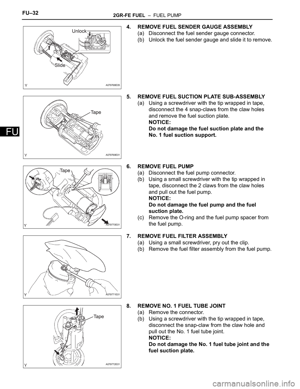
4. REMOVE FUEL SENDER GAUGE ASSEMBLY
(a) Disconnect the fuel sender gauge connector.
(b) Unlock the fuel sender gauge and slide it to remove.
5. REMOVE FUEL SUCTION PLATE SUB-ASSEMBLY
(a) Using a screwdriver with the tip wrapped in tape,
disconnect the 4 snap-claws from the claw holes
and remove the fuel suction plate.
NOTICE:
Do not damage the fuel suction plate and the
No. 1 fuel suction support.
6. REMOVE FUEL PUMP
(a) Disconnect the fuel pump connector.
(b) Using a small screwdriver with the tip wrapped in
tape, disconnect the 2 claws from the claw holes
and pull out the fuel pump.
NOTICE:
Do not damage the fuel pump and the fuel
suction plate.
(c) Remove the O-ring and the fuel pump spacer from
the fuel pump.
7. REMOVE FUEL FILTER ASSEMBLY
(a) Using a small screwdriver, pry out the clip.
(b) Remove the fuel filter assembly from the fuel pump.
8. REMOVE NO. 1 FUEL TUBE JOINT
(a) Remove the connector.
(b) Using a screwdriver with the tip wrapped in tape,
disconnect the snap-claw from the claw hole and
pull out the No. 1 fuel tube joint.
NOTICE:
Do not damage the No. 1 fuel tube joint and the
fuel suction plate.
A079768E05
A079769E01
A079770E01
A079771E01
A079772E01
Page 1152 of 3000
FU–342GR-FE FUEL – FUEL PUMP
FU
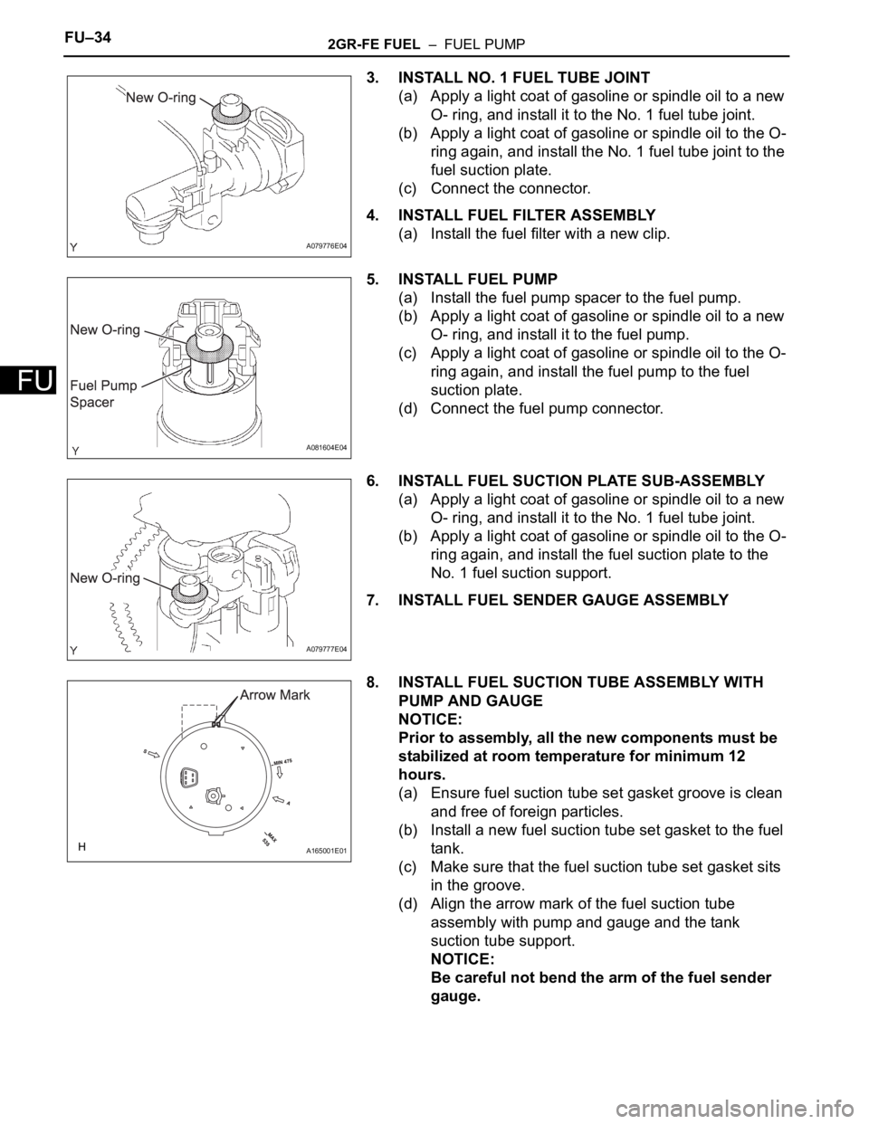
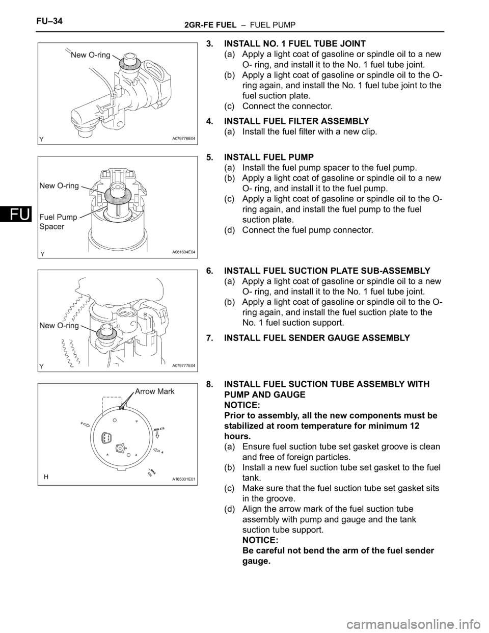
3. INSTALL NO. 1 FUEL TUBE JOINT
(a) Apply a light coat of gasoline or spindle oil to a new
O- ring, and install it to the No. 1 fuel tube joint.
(b) Apply a light coat of gasoline or spindle oil to the O-
ring again, and install the No. 1 fuel tube joint to the
fuel suction plate.
(c) Connect the connector.
4. INSTALL FUEL FILTER ASSEMBLY
(a) Install the fuel filter with a new clip.
5. INSTALL FUEL PUMP
(a) Install the fuel pump spacer to the fuel pump.
(b) Apply a light coat of gasoline or spindle oil to a new
O- ring, and install it to the fuel pump.
(c) Apply a light coat of gasoline or spindle oil to the O-
ring again, and install the fuel pump to the fuel
suction plate.
(d) Connect the fuel pump connector.
6. INSTALL FUEL SUCTION PLATE SUB-ASSEMBLY
(a) Apply a light coat of gasoline or spindle oil to a new
O- ring, and install it to the No. 1 fuel tube joint.
(b) Apply a light coat of gasoline or spindle oil to the O-
ring again, and install the fuel suction plate to the
No. 1 fuel suction support.
7. INSTALL FUEL SENDER GAUGE ASSEMBLY
8. INSTALL FUEL SUCTION TUBE ASSEMBLY WITH
PUMP AND GAUGE
NOTICE:
Prior to assembly, all the new components must be
stabilized at room temperature for minimum 12
hours.
(a) Ensure fuel suction tube set gasket groove is clean
and free of foreign particles.
(b) Install a new fuel suction tube set gasket to the fuel
tank.
(c) Make sure that the fuel suction tube set gasket sits
in the groove.
(d) Align the arrow mark of the fuel suction tube
assembly with pump and gauge and the tank
suction tube support.
NOTICE:
Be careful not bend the arm of the fuel sender
gauge.
A079776E04
A081604E04
A079777E04
A165001E01
Page 1157 of 3000
FU–342GR-FE FUEL – FUEL PUMP
FU
3. INSTALL NO. 1 FUEL TUBE JOINT
(a) Apply a light coat of gasoline or spindle oil to a new
O- ring, and install it to the No. 1 fuel tube joint.
(b) Apply a light coat of gasoline or spindle oil to the O-
ring again, and install the No. 1 fuel tube joint to the
fuel suction plate.
(c) Connect the connector.
4. INSTALL FUEL FILTER ASSEMBLY
(a) Install the fuel filter with a new clip.
5. INSTALL FUEL PUMP
(a) Install the fuel pump spacer to the fuel pump.
(b) Apply a light coat of gasoline or spindle oil to a new
O- ring, and install it to the fuel pump.
(c) Apply a light coat of gasoline or spindle oil to the O-
ring again, and install the fuel pump to the fuel
suction plate.
(d) Connect the fuel pump connector.
6. INSTALL FUEL SUCTION PLATE SUB-ASSEMBLY
(a) Apply a light coat of gasoline or spindle oil to a new
O- ring, and install it to the No. 1 fuel tube joint.
(b) Apply a light coat of gasoline or spindle oil to the O-
ring again, and install the fuel suction plate to the
No. 1 fuel suction support.
7. INSTALL FUEL SENDER GAUGE ASSEMBLY
8. INSTALL FUEL SUCTION TUBE ASSEMBLY WITH
PUMP AND GAUGE
NOTICE:
Prior to assembly, all the new components must be
stabilized at room temperature for minimum 12
hours.
(a) Ensure fuel suction tube set gasket groove is clean
and free of foreign particles.
(b) Install a new fuel suction tube set gasket to the fuel
tank.
(c) Make sure that the fuel suction tube set gasket sits
in the groove.
(d) Align the arrow mark of the fuel suction tube
assembly with pump and gauge and the tank
suction tube support.
NOTICE:
Be careful not bend the arm of the fuel sender
gauge.
A079776E04
A081604E04
A079777E04
A165001E01
Page 1173 of 3000
EC–102GR-FE EMISSION CONTROL – CANISTER
EC
(3) Connect the positive (+) lead to terminal 7 and
the negative (-) lead to terminal 6.
(4) Check that the valve is closed.
If the result is not as specified, replace the
charcoal canister assembly.
(5) Install the detection pump.
INSTALLATION
1. INSTALL CHARCOAL CANISTER ASSEMBLY
(a) Install the 3 bolts and charcoal canister.
Torque: 29 N*m (296 kgf*cm, 21 ft.*lbf)
(b) Connect the purge line hose to the charcoal
canister.
(c) Connect the wire harness clamp.
(d) Connect the vapor pressure sensor connector.
(e) Connect the charcoal canister filter sub-assembly to
the charcoal canister.
(f) Connect the fuel tank vent hose to the charcoal
canister.
2. INSTALL CHARCOAL CANISTER PROTECTOR
(a) Install the 6 bolts and charcoal canister protector.
Torque: 5.0 N*m (51 kgf*cm, 44 in.*lbf)
A128109E01
A162862
Page 1181 of 3000
EC–82GR-FE EMISSION CONTROL – CANISTER
EC
REMOVAL
1. REMOVE CHARCOAL CANISTER PROTECTOR
(a) Remove the 6 bolts and charcoal canister protector.
2. REMOVE CHARCOAL CANISTER ASSEMBLY
(a) Disconnect the fuel tank vent hose from the
charcoal canister.
(1) Push the connector deep inside.
(2) Pinch portion A.
(3) Pull out the connector.
(b) Disconnect the charcoal canister filter sub-assembly
from the charcoal canister.
(1) Push the connector deep inside.
(2) Pinch portion A.
(3) Pull out the connector.
(c) Disconnect the vapor pressure sensor connector.
(d) Disconnect the wire harness clamp.
(e) Disconnect the purge line hose from the charcoal
canister.
(f) Remove the 3 bolts and charcoal canister.
INSPECTION
1. INSPECT CHARCOAL CANISTER ASSEMBLY
(a) Visually check the charcoal canister for cracks or
damage.
If cracks or damage are found, replace the charcoal
canister assembly.
A162860E01
A162861
A162862
A163448