Page 2684 of 3000

STEERING COLUMN – STEERING COLUMN ASSEMBLYSR–11
SR
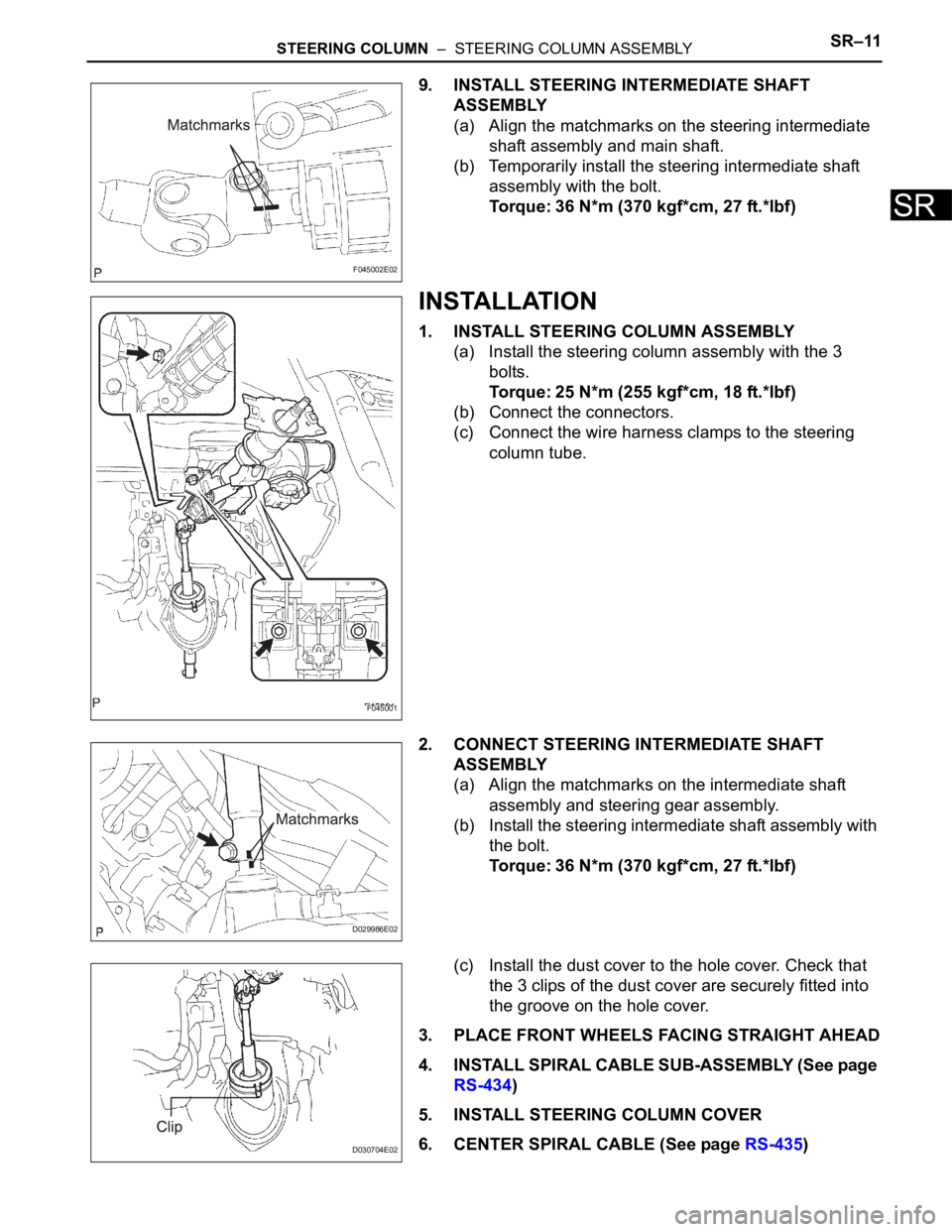
9. INSTALL STEERING INTERMEDIATE SHAFT
ASSEMBLY
(a) Align the matchmarks on the steering intermediate
shaft assembly and main shaft.
(b) Temporarily install the steering intermediate shaft
assembly with the bolt.
Torque: 36 N*m (370 kgf*cm, 27 ft.*lbf)
INSTALLATION
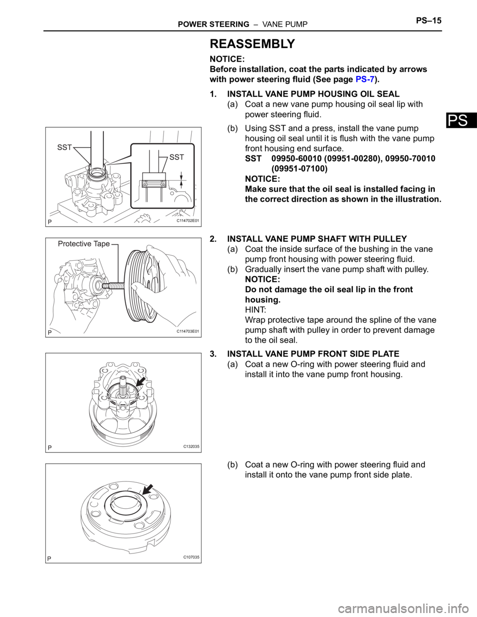
1. INSTALL STEERING COLUMN ASSEMBLY
(a) Install the steering column assembly with the 3
bolts.
Torque: 25 N*m (255 kgf*cm, 18 ft.*lbf)
(b) Connect the connectors.
(c) Connect the wire harness clamps to the steering
column tube.
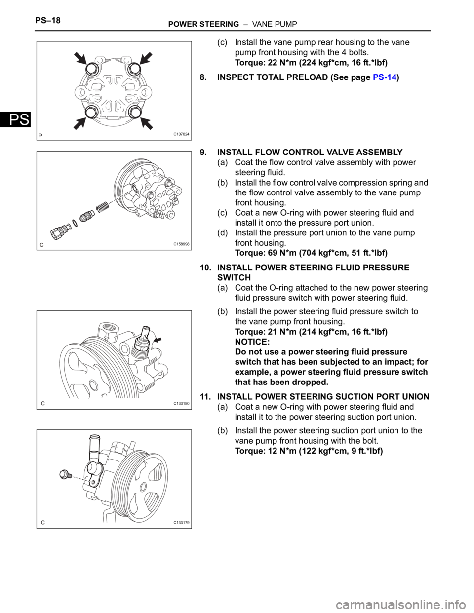
2. CONNECT STEERING INTERMEDIATE SHAFT
ASSEMBLY
(a) Align the matchmarks on the intermediate shaft
assembly and steering gear assembly.
(b) Install the steering intermediate shaft assembly with
the bolt.
Torque: 36 N*m (370 kgf*cm, 27 ft.*lbf)
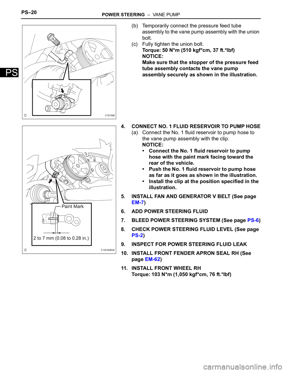
(c) Install the dust cover to the hole cover. Check that
the 3 clips of the dust cover are securely fitted into
the groove on the hole cover.
3. PLACE FRONT WHEELS FACING STRAIGHT AHEAD
4. INSTALL SPIRAL CABLE SUB-ASSEMBLY (See page
RS-434)
5. INSTALL STEERING COLUMN COVER
6. CENTER SPIRAL CABLE (See page RS-435)
F045002E02
F045001
D029986E02
D030704E02
Page 2685 of 3000
SR–12STEERING COLUMN – STEERING COLUMN ASSEMBLY
SR
7. INSTALL STEERING WHEEL ASSEMBLY
(a) Align the matchmarks on the steering wheel
assembly and steering main shaft assembly.
(b) Install the steering wheel assembly set nut.
Torque: 50 N*m (510 kgf*cm, 37 ft.*lbf)
(c) Connect the connector.
8. INSPECT STEERING WHEEL CENTER POINT
9. INSPECT HORN BUTTON ASSEMBLY (See page RS-
425)
10. INSTALL HORN BUTTON ASSEMBLY (See page RS-
424)
11. INSTALL STEERING WHEEL COVER LOWER NO.3
(See page RS-425)
12. INSTALL STEERING WHEEL COVER LOWER NO.2
(See page RS-425)
13. CONNECT BATTERY NEGATIVE TERMINAL
14. INSPECT SRS WARNING LIGHT (See page RS-436)
Page 2686 of 3000

POWER STEERING – VANE PUMPPS–15
PS
REASSEMBLY
NOTICE:
Before installation, coat the parts indicated by arrows
with power steering fluid (See page PS-7).
1. INSTALL VANE PUMP HOUSING OIL SEAL
(a) Coat a new vane pump housing oil seal lip with
power steering fluid.
(b) Using SST and a press, install the vane pump
housing oil seal until it is flush with the vane pump
front housing end surface.
SST 09950-60010 (09951-00280), 09950-70010
(09951-07100)
NOTICE:
Make sure that the oil seal is installed facing in
the correct direction as shown in the illustration.
2. INSTALL VANE PUMP SHAFT WITH PULLEY
(a) Coat the inside surface of the bushing in the vane
pump front housing with power steering fluid.
(b) Gradually insert the vane pump shaft with pulley.
NOTICE:
Do not damage the oil seal lip in the front
housing.
HINT:
Wrap protective tape around the spline of the vane
pump shaft with pulley in order to prevent damage
to the oil seal.
3. INSTALL VANE PUMP FRONT SIDE PLATE
(a) Coat a new O-ring with power steering fluid and
install it into the vane pump front housing.
(b) Coat a new O-ring with power steering fluid and
install it onto the vane pump front side plate.
C114702E01
C114703E01
C132035
C107035
Page 2687 of 3000
PS–16POWER STEERING – VANE PUMP
PS
(c) Align the notch of the vane pump front side plate
with that of the vane pump front housing, and install
the vane pump front side plate.
NOTICE:
Make sure that the vane pump front side plate is
installed facing in the correct direction.
4. INSTALL VANE PUMP CAM RING
(a) Align the notch of the cam ring with that of the vane
pump front side plate, and install the vane pump
cam ring with the inscribed mark facing upward.
NOTICE:
Make sure that the vane pump cam ring is
installed facing in the correct direction.
5. INSTALL VANE PUMP ROTOR
(a) Install the vane pump rotor.
HINT:
The vane pump rotor can be installed in both
directions.
(b) Coat the 10 vane pump plates with power steering
fluid.
C132040E01
C139139E01
C107038
Page 2688 of 3000
POWER STEERING – VANE PUMPPS–17
PS
(c) Install the vane pump plates with the round end
facing outward.
NOTICE:
Make sure that the vane pump plates are
installed facing in the correct direction.
6. INSTALL VANE PUMP SHAFT SNAP RING
(a) Using a screwdriver and a snap ring expander,
install a new vane pump shaft snap ring onto the
vane pump shaft with pulley.
NOTICE:
Make sure that the vane pump shaft snap ring is
securely installed in the vane pump shaft
groove.
7. INSTALL VANE PUMP REAR HOUSING
(a) Coat a new O-ring with power steering fluid and
install it onto the vane pump rear housing.
(b) Align the straight pin of the vane pump rear housing
with the notches of the vane pump cam ring, vane
pump front side plate, and vane pump front housing.
C141370E01
D030336E01
C107040
C136780E01
Page 2689 of 3000

PS–18POWER STEERING – VANE PUMP
PS
(c) Install the vane pump rear housing to the vane
pump front housing with the 4 bolts.
Torque: 22 N*m (224 kgf*cm, 16 ft.*lbf)
8. INSPECT TOTAL PRELOAD (See page PS-14)
9. INSTALL FLOW CONTROL VALVE ASSEMBLY
(a) Coat the flow control valve assembly with power
steering fluid.
(b) Install the flow control valve compression spring and
the flow control valve assembly to the vane pump
front housing.
(c) Coat a new O-ring with power steering fluid and
install it onto the pressure port union.
(d) Install the pressure port union to the vane pump
front housing.
Torque: 69 N*m (704 kgf*cm, 51 ft.*lbf)
10. INSTALL POWER STEERING FLUID PRESSURE
SWITCH
(a) Coat the O-ring attached to the new power steering
fluid pressure switch with power steering fluid.
(b) Install the power steering fluid pressure switch to
the vane pump front housing.
Torque: 21 N*m (214 kgf*cm, 16 ft.*lbf)
NOTICE:
Do not use a power steering fluid pressure
switch that has been subjected to an impact; for
example, a power steering fluid pressure switch
that has been dropped.
11. INSTALL POWER STEERING SUCTION PORT UNION
(a) Coat a new O-ring with power steering fluid and
install it to the power steering suction port union.
(b) Install the power steering suction port union to the
vane pump front housing with the bolt.
Torque: 12 N*m (122 kgf*cm, 9 ft.*lbf)
C107024
C158998
C133180
C133179
Page 2690 of 3000
POWER STEERING – VANE PUMPPS–19
PS
INSTALLATION
1. INSTALL VANE PUMP ASSEMBLY
(a) Temporarily install the bolt to the vane pump
assembly.
(b) Install the vane pump assembly.
(c) Temporarily install the bolt (B).
(d) Using SST, tighten the 2 bolts.
SST 09249-63010
Torque: Without SST
43 N*m (439 kgf*cm, 32 ft.*lbf)
With SST
29 N*m (294 kgf*cm, 21 ft.*lbf)
NOTICE:
• Use a torque wrench with a fulcrum length of
300 mm (11.81 in.).
• This torque value is accurate when SST is
parallel to the torque wrench.
2. CONNECT POWER STEERING FLUID PRESSURE
SWITCH CONNECTOR
(a) Connect the connector to the power steering fluid
pressure switch.
3. CONNECT PRESSURE FEED TUBE ASSEMBLY
(a) Install a new gasket to the pressure feed tube
assembly.
C135238
C159000E01
C161547
Page 2691 of 3000

PS–20POWER STEERING – VANE PUMP
PS
(b) Temporarily connect the pressure feed tube
assembly to the vane pump assembly with the union
bolt.
(c) Fully tighten the union bolt.
Torque: 50 N*m (510 kgf*cm, 37 ft.*lbf)
NOTICE:
Make sure that the stopper of the pressure feed
tube assembly contacts the vane pump
assembly securely as shown in the illustration.
4. CONNECT NO. 1 FLUID RESERVOIR TO PUMP HOSE
(a) Connect the No. 1 fluid reservoir to pump hose to
the vane pump assembly with the clip.
NOTICE:
• Connect the No. 1 fluid reservoir to pump
hose with the paint mark facing toward the
rear of the vehicle.
• Push the No. 1 fluid reservoir to pump hose
as far as it goes as shown in the illustration.
• Install the clip at the position specified in the
illustration.
5. INSTALL FAN AND GENERATOR V BELT (See page
EM-7)
6. ADD POWER STEERING FLUID
7. BLEED POWER STEERING SYSTEM (See page PS-6)
8. CHECK POWER STEERING FLUID LEVEL (See page
PS-2)
9. INSPECT FOR POWER STEERING FLUID LEAK
10. INSTALL FRONT FENDER APRON SEAL RH (See
page EM-62)
11. INSTALL FRONT WHEEL RH
Torque: 103 N*m (1,050 kgf*cm, 76 ft.*lbf)
C161548
C133183E02