Page 2708 of 3000
PS–40POWER STEERING – RACK AND PINION POWER STEERING GEAR
PS
2. CONNECT PRESSURE FEED TUBE ASSEMBLY
(a) Connect the pressure feed tube assembly to the
power steering gear assembly.
(b) Install the clip.
(c) Using SST, connect the return tube assembly to the
power steering gear assembly.
SST 09023-12701
Torque: 22.5 N*m (229 kgf*cm, 17 ft.*lbf)
HINT:
• Use a torque wrench with a fulcrum length of 300
mm (11.81 in.).
• This torque value is effective when SST is
parallel to the torque wrench.
(d) Install the tube clamp with the bolt.
Torque: 9.8 N*m (100 kgf*cm, 87 in.*lbf)
(e) Install the tube clamp with the nut.
Torque: 9.8 N*m (100 kgf*cm, 87 in.*lbf)
D029970
D029977E01
D029974
D029975
Page 2709 of 3000

POWER STEERING – RACK AND PINION POWER STEERING GEARPS–41
PS
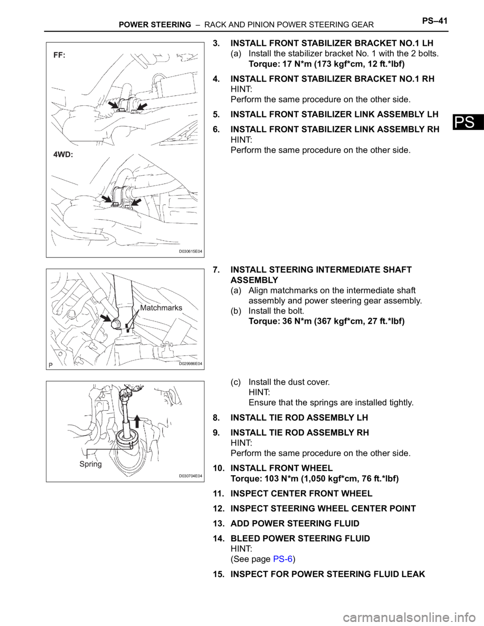
3. INSTALL FRONT STABILIZER BRACKET NO.1 LH
(a) Install the stabilizer bracket No. 1 with the 2 bolts.
Torque: 17 N*m (173 kgf*cm, 12 ft.*lbf)
4. INSTALL FRONT STABILIZER BRACKET NO.1 RH
HINT:
Perform the same procedure on the other side.
5. INSTALL FRONT STABILIZER LINK ASSEMBLY LH
6. INSTALL FRONT STABILIZER LINK ASSEMBLY RH
HINT:
Perform the same procedure on the other side.
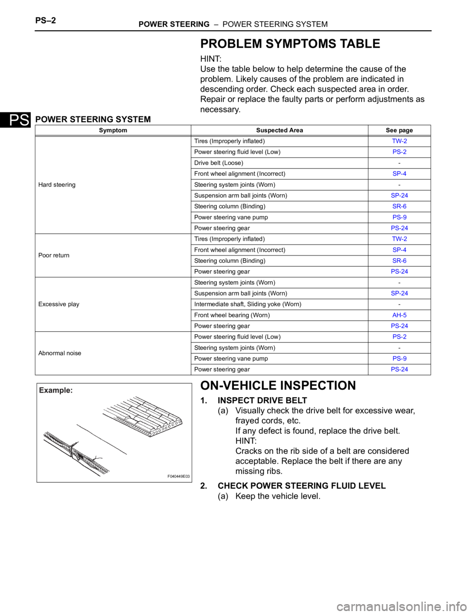
7. INSTALL STEERING INTERMEDIATE SHAFT
ASSEMBLY
(a) Align matchmarks on the intermediate shaft
assembly and power steering gear assembly.
(b) Install the bolt.
Torque: 36 N*m (367 kgf*cm, 27 ft.*lbf)
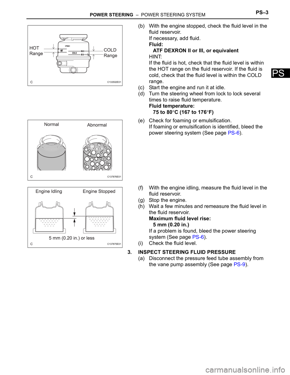
(c) Install the dust cover.
HINT:
Ensure that the springs are installed tightly.
8. INSTALL TIE ROD ASSEMBLY LH
9. INSTALL TIE ROD ASSEMBLY RH
HINT:
Perform the same procedure on the other side.
10. INSTALL FRONT WHEEL
Torque: 103 N*m (1,050 kgf*cm, 76 ft.*lbf)
11. INSPECT CENTER FRONT WHEEL
12. INSPECT STEERING WHEEL CENTER POINT
13. ADD POWER STEERING FLUID
14. BLEED POWER STEERING FLUID
HINT:
(See page PS-6)
15. INSPECT FOR POWER STEERING FLUID LEAK
D030615E04
D029986E04
D030704E04
Page 2710 of 3000
PS–42POWER STEERING – RACK AND PINION POWER STEERING GEAR
PS
16. INSPECT AND ADJUST FRONT WHEEL ALIGNMENT
HINT:
(See page SP-4)
Page 2711 of 3000
POWER STEERING – POWER STEERING SYSTEMPS–1
PS
POWER STEERING SYSTEM
PRECAUTION
1. HANDLING PRECAUTIONS ON STEERING SYSTEM
(a) Care must be taken when replacing parts. Incorrect
replacement could affect the performance of the
steering system and result in a driving hazard.
2. HANDLING PRECAUTIONS ON SRS AIRBAG
SYSTEM
(a) The vehicle is equipped with SRS (Supplemental
Restraint System) such as the driver airbag and
front passenger airbag. Failure to carry out service
operation in correct sequence could cause the SRS
to unexpectedly deploy during servicing, possibly
leading to a serious accident. Before servicing
(including removal or installation of parts, inspection
or replacement), be sure to read the precautionary
notice for the supplemental restraint system (See
page RS-1).
Page 2712 of 3000

PS–2POWER STEERING – POWER STEERING SYSTEM
PS
PROBLEM SYMPTOMS TABLE
HINT:
Use the table below to help determine the cause of the
problem. Likely causes of the problem are indicated in
descending order. Check each suspected area in order.
Repair or replace the faulty parts or perform adjustments as
necessary.
POWER STEERING SYSTEM
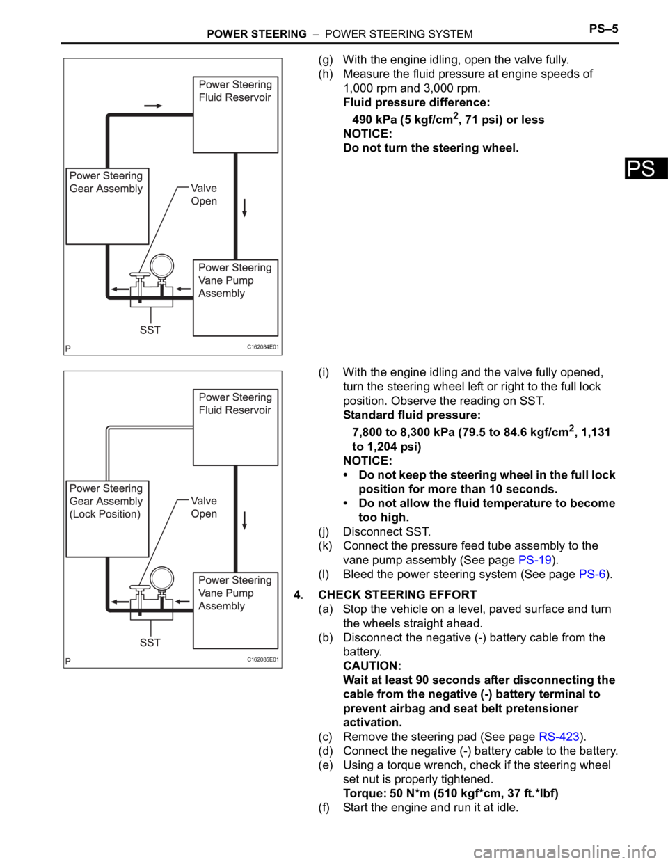
ON-VEHICLE INSPECTION
1. INSPECT DRIVE BELT
(a) Visually check the drive belt for excessive wear,
frayed cords, etc.
If any defect is found, replace the drive belt.
HINT:
Cracks on the rib side of a belt are considered
acceptable. Replace the belt if there are any
missing ribs.
2. CHECK POWER STEERING FLUID LEVEL
(a) Keep the vehicle level.
Symptom Suspected Area See page
Hard steeringTires (Improperly inflated)TW-2
Power steering fluid level (Low)PS-2
Drive belt (Loose) -
Front wheel alignment (Incorrect)SP-4
Steering system joints (Worn) -
Suspension arm ball joints (Worn)SP-24
Steering column (Binding)SR-6
Power steering vane pumpPS-9
Power steering gearPS-24
Poor returnTires (Improperly inflated)TW-2
Front wheel alignment (Incorrect)SP-4
Steering column (Binding)SR-6
Power steering gearPS-24
Excessive playSteering system joints (Worn) -
Suspension arm ball joints (Worn)SP-24
Intermediate shaft, Sliding yoke (Worn) -
Front wheel bearing (Worn)AH-5
Power steering gearPS-24
Abnormal noisePower steering fluid level (Low)PS-2
Steering system joints (Worn) -
Power steering vane pumpPS-9
Power steering gearPS-24
F040449E03
Page 2713 of 3000

POWER STEERING – POWER STEERING SYSTEMPS–3
PS
(b) With the engine stopped, check the fluid level in the
fluid reservoir.
If necessary, add fluid.
Fluid:
ATF DEXRON II or III, or equivalent
HINT:
If the fluid is hot, check that the fluid level is within
the HOT range on the fluid reservoir. If the fluid is
cold, check that the fluid level is within the COLD
range.
(c) Start the engine and run it at idle.
(d) Turn the steering wheel from lock to lock several
times to raise fluid temperature.
Fluid temperature:
75 to 80
C (167 to 176F)
(e) Check for foaming or emulsification.
If foaming or emulsification is identified, bleed the
power steering system (See page PS-6).
(f) With the engine idling, measure the fluid level in the
fluid reservoir.
(g) Stop the engine.
(h) Wait a few minutes and remeasure the fluid level in
the fluid reservoir.
Maximum fluid level rise:
5 mm (0.20 in.)
If a problem is found, bleed the power steering
system (See page PS-6).
(i) Check the fluid level.
3. INSPECT STEERING FLUID PRESSURE
(a) Disconnect the pressure feed tube assembly from
the vane pump assembly (See page PS-9).
C133502E01
C137876E01
C137875E01
Page 2714 of 3000
PS–4POWER STEERING – POWER STEERING SYSTEM
PS
(b) Connect SST as shown in the illustration.
SST 09640-10010 (09641-01010, 09641-01060,
09641-01030)
NOTICE:
Check that the valve of SST is in the open
position.
(c) Bleed the power steering system (See page PS-6).
(d) Start the engine and run it at idle.
(e) Turn the steering wheel from lock to lock several
times to raise fluid temperature.
Fluid temperature:
75 to 80
C (167 to 176F)
(f) With the engine idling, close the valve of SST and
observe the reading on SST.
Standard fluid pressure:
7,800 to 8,300 kPa (79.5 to 84.6 kgf/cm
2, 1,131
to 1,204 psi)
NOTICE:
• Do not keep the valve closed for more than 10
seconds.
• Do not allow the fluid temperature to become
too high.
C133506E01
C162083E01
Page 2715 of 3000

POWER STEERING – POWER STEERING SYSTEMPS–5
PS
(g) With the engine idling, open the valve fully.
(h) Measure the fluid pressure at engine speeds of
1,000 rpm and 3,000 rpm.
Fluid pressure difference:
490 kPa (5 kgf/cm
2, 71 psi) or less
NOTICE:
Do not turn the steering wheel.
(i) With the engine idling and the valve fully opened,
turn the steering wheel left or right to the full lock
position. Observe the reading on SST.
Standard fluid pressure:
7,800 to 8,300 kPa (79.5 to 84.6 kgf/cm
2, 1,131
to 1,204 psi)
NOTICE:
• Do not keep the steering wheel in the full lock
position for more than 10 seconds.
• Do not allow the fluid temperature to become
too high.
(j) Disconnect SST.
(k) Connect the pressure feed tube assembly to the
vane pump assembly (See page PS-19).
(l) Bleed the power steering system (See page PS-6).
4. CHECK STEERING EFFORT
(a) Stop the vehicle on a level, paved surface and turn
the wheels straight ahead.
(b) Disconnect the negative (-) battery cable from the
battery.
CAUTION:
Wait at least 90 seconds after disconnecting the
cable from the negative (-) battery terminal to
prevent airbag and seat belt pretensioner
activation.
(c) Remove the steering pad (See page RS-423).
(d) Connect the negative (-) battery cable to the battery.
(e) Using a torque wrench, check if the steering wheel
set nut is properly tightened.
Torque: 50 N*m (510 kgf*cm, 37 ft.*lbf)
(f) Start the engine and run it at idle.
C162084E01
C162085E01