2007 NISSAN TIIDA low oil pressure
[x] Cancel search: low oil pressurePage 3290 of 5883
HA-8
< PRECAUTION >
PRECAUTIONS
O-Ring Part Numbers and Specifications
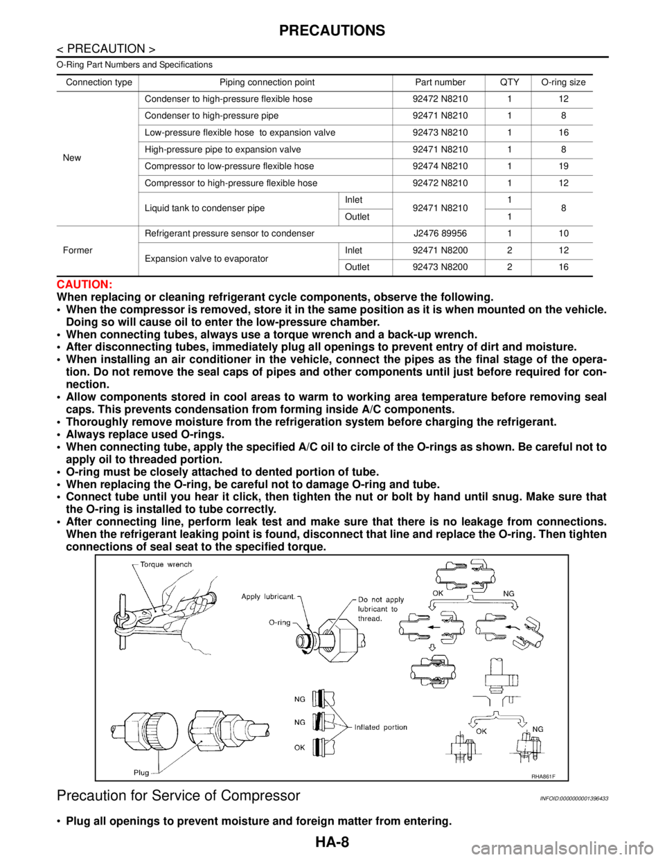
CAUTION:
When replacing or cleaning refrigerant cycle components, observe the following.
When the compressor is removed, store it in the same position as it is when mounted on the vehicle.
Doing so will cause oil to enter the low-pressure chamber.
When connecting tubes, always use a torque wrench and a back-up wrench.
After disconnecting tubes, immediately plug all openings to prevent entry of dirt and moisture.
When installing an air conditioner in the vehicle, connect the pipes as the final stage of the opera-
tion. Do not remove the seal caps of pipes and other components until just before required for con-
nection.
Allow components stored in cool areas to warm to working area temperature before removing seal
caps. This prevents condensation from forming inside A/C components.
Thoroughly remove moisture from the refrigeration system before charging the refrigerant.
Always replace used O-rings.
When connecting tube, apply the specified A/C oil to circle of the O-rings as shown. Be careful not to
apply oil to threaded portion.
O-ring must be closely attached to dented portion of tube.
When replacing the O-ring, be careful not to damage O-ring and tube.
Connect tube until you hear it click, then tighten the nut or bolt by hand until snug. Make sure that
the O-ring is installed to tube correctly.
After connecting line, perform leak test and make sure that there is no leakage from connections.
When the refrigerant leaking point is found, disconnect that line and replace the O-ring. Then tighten
connections of seal seat to the specified torque.
Precaution for Service of CompressorINFOID:0000000001396433
Plug all openings to prevent moisture and foreign matter from entering.
Connection type Piping connection point Part number QTY O-ring size
NewCondenser to high-pressure flexible hose 92472 N8210 1 12
Condenser to high-pressure pipe 92471 N8210 1 8
Low-pressure flexible hose to expansion valve 92473 N8210 1 16
High-pressure pipe to expansion valve 92471 N8210 1 8
Compressor to low-pressure flexible hose 92474 N8210 1 19
Compressor to high-pressure flexible hose 92472 N8210 1 12
Liquid tank to condenser pipeInlet
92471 N82101
8
Outlet 1
FormerRefrigerant pressure sensor to condenser J2476 89956 1 10
Expansion valve to evaporatorInlet 92471 N8200 2 12
Outlet 92473 N8200 2 16
RHA861F
Page 3291 of 5883
PRECAUTIONS
HA-9
< PRECAUTION >
C
D
E
F
G
H
J
K
L
MA
B
HA
N
O
P
When the compressor is removed, store it in the same position as it is when mounted on the car.
When replacing or repairing compressor, follow “Maintenance of Oil Quantity in Compressor”
exactly. Refer to HA-19, "
Maintenance of Oil Quantity in Compressor".
Keep friction surfaces between clutch and pulley clean. If the surface is contaminated, with oil, wipe
it off by using a clean waste cloth moistened with thinner.
After compressor service operation, turn the compressor shaft by hand more than five turns in both
directions. This will equally distribute oil inside the compressor. After the compressor is installed,
let the engine idle and operate the compressor for one hour.
After replacing the compressor magnet clutch, apply voltage to the new one and check for usual
operation.
Precaution for Service EquipmentINFOID:0000000001396434
RECOVERY/RECYCLING EQUIPMENT
Be certain to follow the manufacturer’s instructions for machine operation and machine maintenance. Never
introduce any refrigerant other than that specified into the machine.
ELECTRONIC LEAK DETECTOR
Be certain to follow the manufacturer’s instructions for tester operation and tester maintenance.
VACUUM PUMP
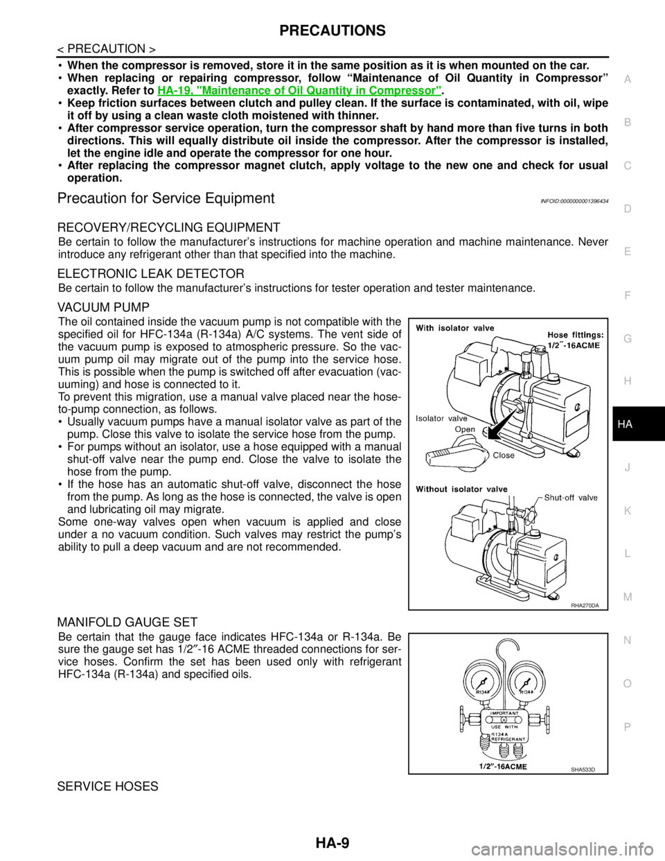
The oil contained inside the vacuum pump is not compatible with the
specified oil for HFC-134a (R-134a) A/C systems. The vent side of
the vacuum pump is exposed to atmospheric pressure. So the vac-
uum pump oil may migrate out of the pump into the service hose.
This is possible when the pump is switched off after evacuation (vac-
uuming) and hose is connected to it.
To prevent this migration, use a manual valve placed near the hose-
to-pump connection, as follows.
Usually vacuum pumps have a manual isolator valve as part of the
pump. Close this valve to isolate the service hose from the pump.
For pumps without an isolator, use a hose equipped with a manual
shut-off valve near the pump end. Close the valve to isolate the
hose from the pump.
If the hose has an automatic shut-off valve, disconnect the hose
from the pump. As long as the hose is connected, the valve is open
and lubricating oil may migrate.
Some one-way valves open when vacuum is applied and close
under a no vacuum condition. Such valves may restrict the pump’s
ability to pull a deep vacuum and are not recommended.
MANIFOLD GAUGE SET
Be certain that the gauge face indicates HFC-134a or R-134a. Be
sure the gauge set has 1/2″-16 ACME threaded connections for ser-
vice hoses. Confirm the set has been used only with refrigerant
HFC-134a (R-134a) and specified oils.
SERVICE HOSES
RHA270DA
SHA533D
Page 3306 of 5883
HA-24
< ON-VEHICLE MAINTENANCE >
FLUORESCENT LEAK DETECTOR
FLUORESCENT LEAK DETECTOR
Checking System for Leaks Using the Fluorescent Leak DetectorINFOID:0000000001396445
1. Check A/C system for leaks using the UV lamp and safety goggles J-42220 in a low sunlight area (area
without windows preferable). Illuminate all components, fittings and lines. The dye will appear as a bright
green/yellow area at the point of leakage. Fluorescent dye observed at the evaporator drain opening indi-
cates an evaporator core assembly (tubes, core or expansion valve) leak.
2. If the suspected area is difficult to see, use an adjustable mirror or wipe the area with a clean shop rag or
cloth, with the UV lamp for dye residue.
3. After the leak is repaired, remove any residual dye using dye cleaner J-43872 to prevent future misdiag-
nosis.
4. Perform a system performance check and verify the leak repair with an approved electronic refrigerant
leak detector.
NOTE:
Other gases in the work area or substances on the A/C components, for example, anti-freeze, windshield
washer fluid, solvents and oils, may falsely trigger the leak detector. Make sure the surfaces to be checked are
clean.
Clean with a dry cloth or blow off with shop air.
Do not allow the sensor tip of the detector to contact with any substance. This can also cause false readings
and may damage the detector.
Dye InjectionINFOID:0000000001396446
(This procedure is only necessary when recharging the system or when the compressor has seized and was
replaced.)
1. Check A/C system static (at rest) pressure. Pressure must be at least 345 kPa (3.45 bar, 3.52 kg/cm
2, 50
psi).
2. Pour one bottle (1/4 ounce / 7.4 cc) of the A/C refrigerant dye into the injector tool J-41459.
3. Connect the injector tool to the A/C low-pressure side service fitting.
4. Start engine and switch A/C ON.
5. When the A/C operating (compressor running), inject one bottle (1/4 ounce / 7.4 cc) of fluorescent dye
through the low-pressure service valve using dye injector tool J-41459 (refer to the manufacture’s operat-
ing instructions).
6. With the engine still running, disconnect the injector tool from the service fitting.
CAUTION:
Be careful the A/C system or replacing a component, pour the dye directly into the open system
connection and proceed with the service procedures.
7. Operate the A/C system for a minimum of 20 minutes to mix the dye with the system oil. Depending on the
leak size, operating conditions and location of the leak, it may take from minutes to days for the dye to
penetrate a leak and become visible.
Page 3315 of 5883
COMPRESSOR
HA-33
< ON-VEHICLE REPAIR >
C
D
E
F
G
H
J
K
L
MA
B
HA
N
O
P
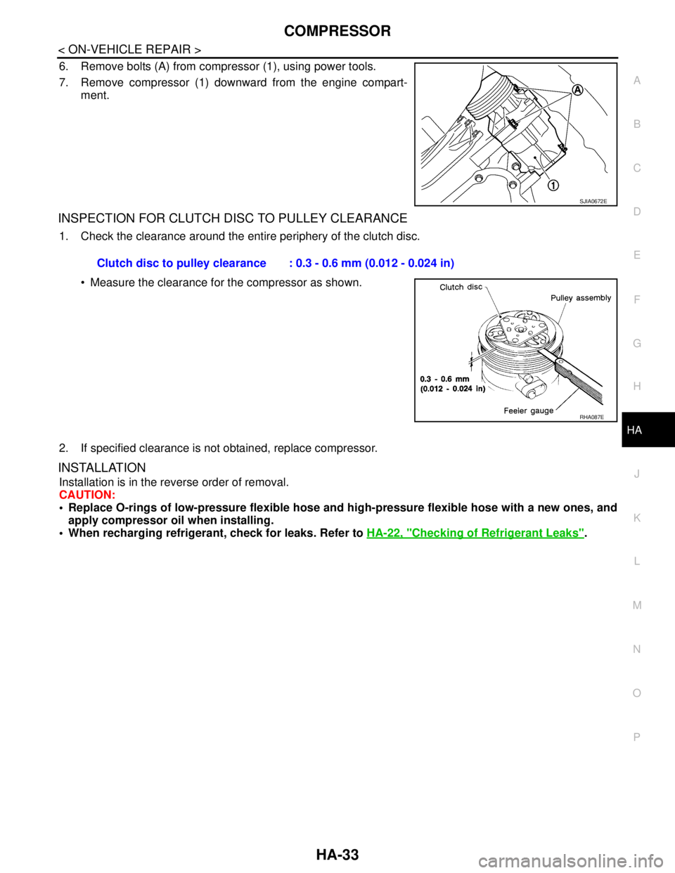
6. Remove bolts (A) from compressor (1), using power tools.
7. Remove compressor (1) downward from the engine compart-
ment.
INSPECTION FOR CLUTCH DISC TO PULLEY CLEARANCE
1. Check the clearance around the entire periphery of the clutch disc.
Measure the clearance for the compressor as shown.
2. If specified clearance is not obtained, replace compressor.
INSTALLATION
Installation is in the reverse order of removal.
CAUTION:
Replace O-rings of low-pressure flexible hose and high-pressure flexible hose with a new ones, and
apply compressor oil when installing.
When recharging refrigerant, check for leaks. Refer to HA-22, "
Checking of Refrigerant Leaks".
SJIA0672E
Clutch disc to pulley clearance : 0.3 - 0.6 mm (0.012 - 0.024 in)
RHA087E
Page 3317 of 5883
COMPRESSOR
HA-35
< ON-VEHICLE REPAIR >
C
D
E
F
G
H
J
K
L
MA
B
HA
N
O
P
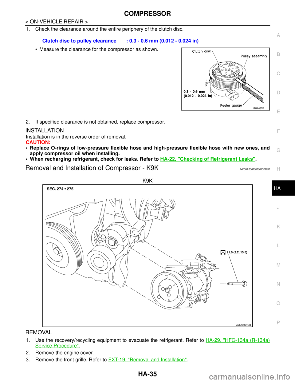
1. Check the clearance around the entire periphery of the clutch disc.
Measure the clearance for the compressor as shown.
2. If specified clearance is not obtained, replace compressor.
INSTALLATION
Installation is in the reverse order of removal.
CAUTION:
Replace O-rings of low-pressure flexible hose and high-pressure flexible hose with new ones, and
apply compressor oil when installing.
When recharging refrigerant, check for leaks. Refer to HA-22, "
Checking of Refrigerant Leaks".
Removal and Installation of Compressor - K9KINFOID:0000000001523297
K9K
REMOVAL
1. Use the recovery/recycling equipment to evacuate the refrigerant. Refer to HA-29, "HFC-134a (R-134a)
Service Procedure".
2. Remove the engine cover.
3. Remove the front grille. Refer to EXT-19, "
Removal and Installation". Clutch disc to pulley clearance : 0.3 - 0.6 mm (0.012 - 0.024 in)
RHA087E
ALIIA0094GB
Page 3318 of 5883
HA-36
< ON-VEHICLE REPAIR >
COMPRESSOR
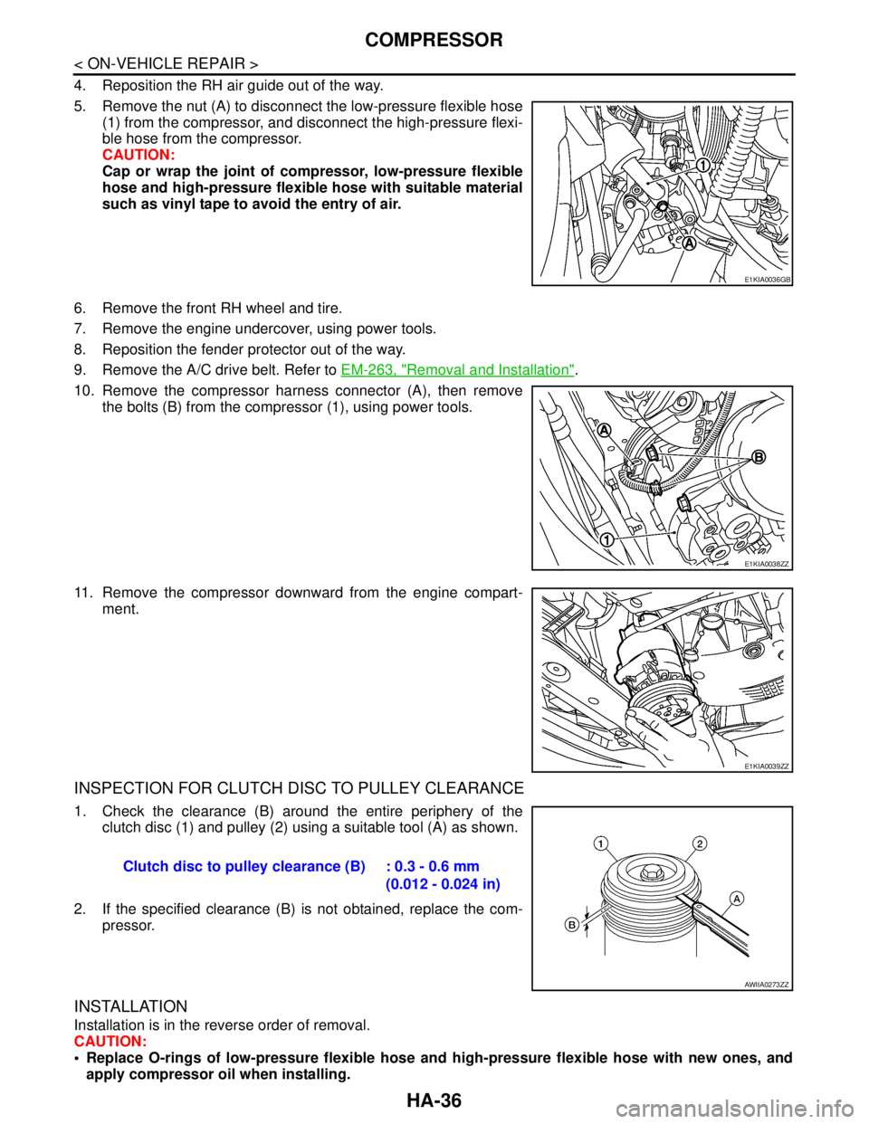
4. Reposition the RH air guide out of the way.
5. Remove the nut (A) to disconnect the low-pressure flexible hose
(1) from the compressor, and disconnect the high-pressure flexi-
ble hose from the compressor.
CAUTION:
Cap or wrap the joint of compressor, low-pressure flexible
hose and high-pressure flexible hose with suitable material
such as vinyl tape to avoid the entry of air.
6. Remove the front RH wheel and tire.
7. Remove the engine undercover, using power tools.
8. Reposition the fender protector out of the way.
9. Remove the A/C drive belt. Refer to EM-263, "
Removal and Installation".
10. Remove the compressor harness connector (A), then remove
the bolts (B) from the compressor (1), using power tools.
11. Remove the compressor downward from the engine compart-
ment.
INSPECTION FOR CLUTCH DISC TO PULLEY CLEARANCE
1. Check the clearance (B) around the entire periphery of the
clutch disc (1) and pulley (2) using a suitable tool (A) as shown.
2. If the specified clearance (B) is not obtained, replace the com-
pressor.
INSTALLATION
Installation is in the reverse order of removal.
CAUTION:
Replace O-rings of low-pressure flexible hose and high-pressure flexible hose with new ones, and
apply compressor oil when installing.
E1KIA0036GB
E1KIA0038ZZ
E1KIA0039ZZ
Clutch disc to pulley clearance (B) : 0.3 - 0.6 mm
(0.012 - 0.024 in)
AWIIA0273ZZ
Page 3320 of 5883
HA-38
< ON-VEHICLE REPAIR >
LOW-PRESSURE FLEXIBLE HOSE
LOW-PRESSURE FLEXIBLE HOSE
Removal and Installation of Low-Pressure Flexible Hose - MR18DE, HR16DE
INFOID:0000000001404150
REMOVAL
1. Use the recovery/recycling equipment to evacuate the refrigerant. Refer to HA-21, "HFC-134a (R-134a)
Service Procedure".
2. Remove engine cover.
3. Remove cowl top cover. Refer to EXT-20, "
Removal and Installation".
4. Remove lower dash insulator.
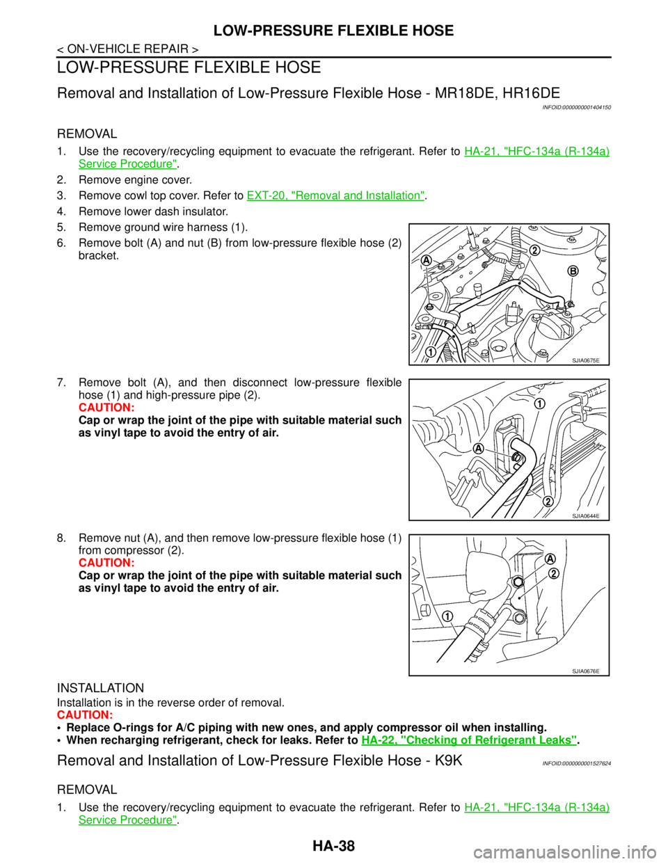
5. Remove ground wire harness (1).
6. Remove bolt (A) and nut (B) from low-pressure flexible hose (2)
bracket.
7. Remove bolt (A), and then disconnect low-pressure flexible
hose (1) and high-pressure pipe (2).
CAUTION:
Cap or wrap the joint of the pipe with suitable material such
as vinyl tape to avoid the entry of air.
8. Remove nut (A), and then remove low-pressure flexible hose (1)
from compressor (2).
CAUTION:
Cap or wrap the joint of the pipe with suitable material such
as vinyl tape to avoid the entry of air.
INSTALLATION
Installation is in the reverse order of removal.
CAUTION:
Replace O-rings for A/C piping with new ones, and apply compressor oil when installing.
When recharging refrigerant, check for leaks. Refer to HA-22, "
Checking of Refrigerant Leaks".
Removal and Installation of Low-Pressure Flexible Hose - K9KINFOID:0000000001527624
REMOVAL
1. Use the recovery/recycling equipment to evacuate the refrigerant. Refer to HA-21, "HFC-134a (R-134a)
Service Procedure".
SJIA0675E
SJIA0644E
SJIA0676E
Page 3321 of 5883

LOW-PRESSURE FLEXIBLE HOSE
HA-39
< ON-VEHICLE REPAIR >
C
D
E
F
G
H
J
K
L
MA
B
HA
N
O
P
2. Remove the engine cover.
3. Remove the front grille. Refer to EXT-19, "
Removal and Installation".
4. Reposition the RH air guide out of the way.
5. Remove the nut (A) to disconnect the low-pressure flexible hose
(1) from the compressor.
CAUTION:
Cap or wrap the joint of compressor, low-pressure flexible
hose and high-pressure flexible hose with suitable material
such as vinyl tape to avoid the entry of air.
6. Disconnect the low-pressure pipe from the low-pressure flexible hose.
CAUTION:
Cap or wrap the joint of the pipe with suitable material such as vinyl tape to avoid the entry of air.
7. Remove the low-pressure flexible hose.
INSTALLATION
Installation is in the reverse order of removal.
CAUTION:
Replace O-rings for A/C piping with new ones, and apply compressor oil when installing.
When recharging refrigerant, check for leaks. Refer to HA-22, "
Checking of Refrigerant Leaks".
E1KIA0036GB