2007 NISSAN TIIDA low oil pressure
[x] Cancel search: low oil pressurePage 4276 of 5883
MA-36
< ON-VEHICLE MAINTENANCE >
ENGINE MAINTENANCE (MR18DE)
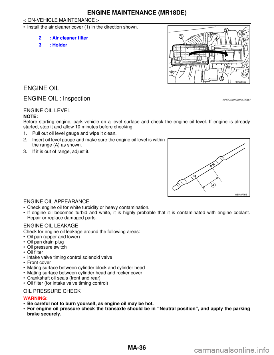
Install the air cleaner cover (1) in the direction shown.
ENGINE OIL
ENGINE OIL : InspectionINFOID:0000000001730867
ENGINE OIL LEVEL
NOTE:
Before starting engine, park vehicle on a level surface and check the engine oil level. If engine is already
started, stop it and allow 10 minutes before checking.
1. Pull out oil level gauge and wipe it clean.
2. Insert oil level gauge and make sure the engine oil level is within
the range (A) as shown.
3. If it is out of range, adjust it.
ENGINE OIL APPEARANCE
Check engine oil for white turbidity or heavy contamination.
If engine oil becomes turbid and white, it is highly probable that it is contaminated with engine coolant.
Repair or replace damaged parts.
ENGINE OIL LEAKAGE
Check for engine oil leakage around the following areas:
Oil pan (upper and lower)
Oil pan drain plug
Oil pressure switch
Oil filter
Intake valve timing control solenoid valve
Front cover
Mating surface between cylinder block and cylinder head
Mating surface between cylinder head and rocker cover
Crankshaft oil seals (front and rear)
Oil filter (for intake valve timing control)
OIL PRESSURE CHECK
WARNING:
Be careful not to burn yourself, as engine oil may be hot.
For engine oil pressure check the transaxle should be in “Neutral position”, and apply the parking
brake securely.2 : Air cleaner filter
3 : Holder
PBIC3559J
WBIA0776E
Page 4277 of 5883
ENGINE MAINTENANCE (MR18DE)
MA-37
< ON-VEHICLE MAINTENANCE >
C
D
E
F
G
H
I
J
K
L
MB
MAN
OA
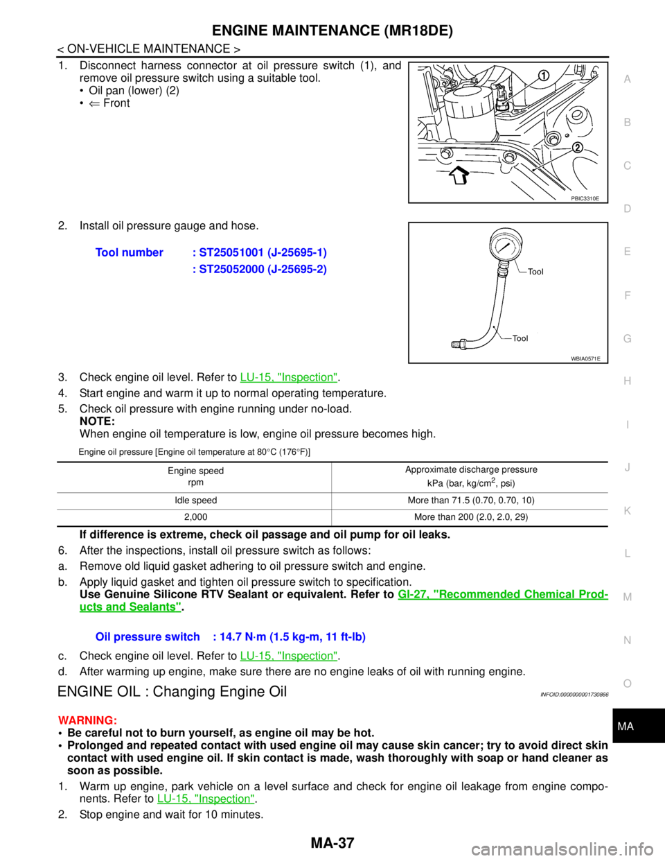
1. Disconnect harness connector at oil pressure switch (1), and
remove oil pressure switch using a suitable tool.
Oil pan (lower) (2)
⇐ Front
2. Install oil pressure gauge and hose.
3. Check engine oil level. Refer to LU-15, "
Inspection".
4. Start engine and warm it up to normal operating temperature.
5. Check oil pressure with engine running under no-load.
NOTE:
When engine oil temperature is low, engine oil pressure becomes high.
Engine oil pressure [Engine oil temperature at 80°C (176°F)]
If difference is extreme, check oil passage and oil pump for oil leaks.
6. After the inspections, install oil pressure switch as follows:
a. Remove old liquid gasket adhering to oil pressure switch and engine.
b. Apply liquid gasket and tighten oil pressure switch to specification.
Use Genuine Silicone RTV Sealant or equivalent. Refer to GI-27, "
Recommended Chemical Prod-
ucts and Sealants".
c. Check engine oil level. Refer to LU-15, "
Inspection".
d. After warming up engine, make sure there are no engine leaks of oil with running engine.
ENGINE OIL : Changing Engine OilINFOID:0000000001730866
WARNING:
Be careful not to burn yourself, as engine oil may be hot.
Prolonged and repeated contact with used engine oil may cause skin cancer; try to avoid direct skin
contact with used engine oil. If skin contact is made, wash thoroughly with soap or hand cleaner as
soon as possible.
1. Warm up engine, park vehicle on a level surface and check for engine oil leakage from engine compo-
nents. Refer to LU-15, "
Inspection".
2. Stop engine and wait for 10 minutes.
PBIC3310E
Tool number : ST25051001 (J-25695-1)
: ST25052000 (J-25695-2)
WBIA0571E
Engine speed
rpm Approximate discharge pressure
kPa (bar, kg/cm2, psi)
Idle speed More than 71.5 (0.70, 0.70, 10)
2,000 More than 200 (2.0, 2.0, 29)
Oil pressure switch : 14.7 N·m (1.5 kg-m, 11 ft-lb)
Page 4287 of 5883
ENGINE MAINTENANCE (K9K)
MA-47
< ON-VEHICLE MAINTENANCE >
C
D
E
F
G
H
I
J
K
L
MB
MAN
OA
ENGINE OIL : InspectionINFOID:0000000001730878
OIL LEVEL AND MUDDINESS
Before starting the engine, check the oil level placing the vehicle
on a level surface. If the engine is already started, stop it and allow
10 minutes before checking.
Make sure the oil level is within the range shown.
If it is out of range, adjust it.
Check the oil for white turbidity or remarkable contamination.
If the oil becomes turbid and white, it is highly probable that it is
contaminated with coolant. Find the cause and repair.
OIL LEAKAGE
Check for oil leakage around the following area.
Oil pan
Oil pan drain plug
Oil pressure switch
Oil filter bracket
Vacuum pump
Oil pump housing
Mating surface between cylinder block and cylinder head
Mating surface between cylinder head and rocker cover
Oil cooler
Crankshaft oil seals
OIL PRESSURE CHECK
WARNING:
Be careful not to burn yourself, as the engine oil is hot.
Oil pressure check should be done in Neutral “N” position.
1. Check the engine oil level.
2. Remove engine undercover using power tool.
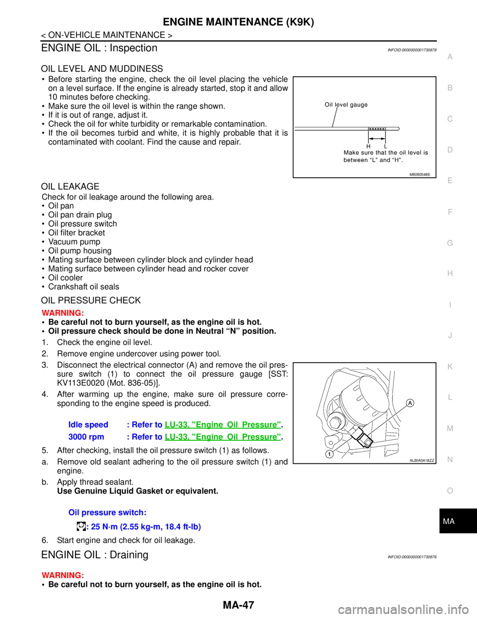
3. Disconnect the electrical connector (A) and remove the oil pres-
sure switch (1) to connect the oil pressure gauge [SST:
KV113E0020 (Mot. 836-05)].
4. After warming up the engine, make sure oil pressure corre-
sponding to the engine speed is produced.
5. After checking, install the oil pressure switch (1) as follows.
a. Remove old sealant adhering to the oil pressure switch (1) and
engine.
b. Apply thread sealant.
Use Genuine Liquid Gasket or equivalent.
6. Start engine and check for oil leakage.
ENGINE OIL : DrainingINFOID:0000000001730876
WARNING:
Be careful not to burn yourself, as the engine oil is hot.
MBIB0548E
Idle speed : Refer to LU-33, "EngineOilPressure".
3000 rpm : Refer to LU-33, "
EngineOilPressure".
Oil pressure switch:
: 25 N·m (2.55 kg-m, 18.4 ft-lb)
ALBIA0418ZZ
Page 4314 of 5883
MWI
METER SYSTEM
MWI-7
< FUNCTION DIAGNOSIS >
C
D
E
F
G
H
I
J
K
L
MB A
O
P
METER SYSTEM : Component DescriptionINFOID:0000000001537306
SPEEDOMETER
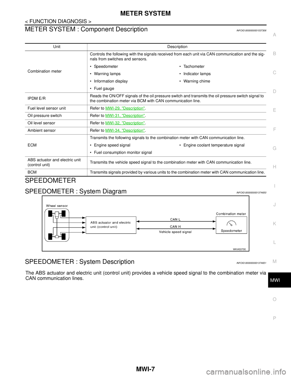
SPEEDOMETER : System DiagramINFOID:0000000001374650
SPEEDOMETER : System DescriptionINFOID:0000000001374651
The ABS actuator and electric unit (control unit) provides a vehicle speed signal to the combination meter via
CAN communication lines.
Unit Description
Combination meterControls the following with the signals received from each unit via CAN communication and the sig-
nals from switches and sensors.
Speedometer Tachometer
Warning lamps Indicator lamps
Information display Warning chime
Fuel gauge
IPDM E/RReads the ON/OFF signals of the oil pressure switch and transmits the oil pressure switch signal to
the combination meter via BCM with CAN communication line.
Fuel level sensor unit Refer to MWI-29, "
Description".
Oil pressure switch Refer to MWI-31, "
Description".
Oil level sensor Refer to MWI-32, "
Description".
Ambient sensor Refer to MWI-34, "
Description".
ECMTransmits the following signals to the combination meter with CAN communication line.
Engine speed signal Engine coolant temperature signal
Fuel consumption monitor signal
ABS actuator and electric unit
(control unit)Transmits the vehicle speed signal to the combination meter with CAN communication line.
BCM Transmits signals provided by various units to the combination meter with CAN communication line.
WKIA5370E
Page 4324 of 5883
MWI
METER SYSTEM
MWI-17
< FUNCTION DIAGNOSIS >
C
D
E
F
G
H
I
J
K
L
MB A
O
P
WARNING LAMPS/INDICATOR LAMPS : Component DescriptionINFOID:0000000001537300
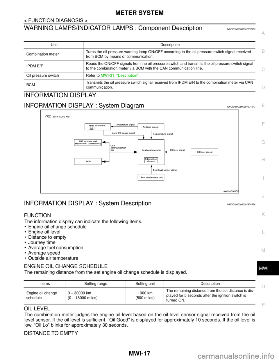
INFORMATION DISPLAY
INFORMATION DISPLAY : System DiagramINFOID:0000000001374677
INFORMATION DISPLAY : System DescriptionINFOID:0000000001374678
FUNCTION
The information display can indicate the following items.
Engine oil change schedule
Engine oil level
Distance to empty
Journey time
Average fuel consumption
Average speed
Outside air temperature
ENGINE OIL CHANGE SCHEDULE
The remaining distance from the set engine oil change schedule is displayed.
OIL LEVEL
The combination meter judges the engine oil level based on the oil level sensor signal received from the oil
level sensor. If the oil level is sufficient, “Oil Good” is displayed for approximately 10 seconds. If the oil level is
low, “Oil Lo” blinks for approximately 30 seconds.
DISTANCE TO EMPTY
Unit Description
Combination meterTurns the oil pressure warning lamp ON/OFF according to the oil pressure switch signal received
from BCM by means of communication.
IPDM E/RReads the ON/OFF signals from the oil pressure switch and transmits the oil pressure switch signal
to the combination meter via BCM with the CAN communication line.
Oil pressure switch Refer to MWI-31, "
Description".
BCMTransmits the oil pressure switch signal received from IPDM E/R to the combination meter via CAN
communication.
AWNIA0163GB
Items Setting range Setting unit Description
Engine oil change
schedule0 – 30000 km
(0 – 18000 miles)1000 km
(500 miles)The remaining distance from the set distance is dis-
played for 5 seconds after the ignition switch is
turned ON.
Page 4330 of 5883

MWI
DIAGNOSIS SYSTEM (METER)
MWI-23
< FUNCTION DIAGNOSIS >
C
D
E
F
G
H
I
J
K
L
MB A
O
P
NOTE:
Some items are not available due to vehicle specification.
*: The monitor will indicate “OFF” even though the brake warning lamp is on if either of the following conditions exist.
The parking brake is engaged
The brake fluid level is lowDOOR W/L [ON/OFF] X Displays [ON/OFF] condition of door warning lamp.
HI-BEAM IND [ON/OFF] X Displays [ON/OFF] condition of high beam indicator.
TURN IND [ON/OFF] X Displays [ON/OFF] condition of turn indicator.
FR FOG IND X Displays [ON/OFF] condition of front fog lamp indicator.
RR FOG IND X Displays [ON/OFF] condition of rear fog lamp indicator.
OIL W/L [ON/OFF] X Displays [ON/OFF] condition of oil pressure warning lamp.
LIGHT IND X Displays [ON/OFF] condition of exterior lamp indicator.
VDC/TCS IND [ON/OFF] X Displays [ON/OFF] condition of VDC OFF indicator lamp.
ABS W/L [ON/OFF] X Displays [ON/OFF] condition of ABS warning lamp.
SLIP IND [ON/OFF] X Displays [ON/OFF] condition of SLIP indicator lamp.
BRAKE W/L [ON/OFF] X Displays [ON/OFF] condition of brake warning lamp.*
OIL LEVEL IND X Displays [ON/OFF] condition of oil level indicator.
KEY G W/L [ON/OFF] X Displays [ON/OFF] condition of key green warning lamp.
KEY R W/L [ON/OFF] X Displays [ON/OFF] condition of key red warning lamp.
KEY KNOB W/L [ON/OFF] X Displays [ON/OFF] condition of key knob warning lamp.
PNP P SW X X Displays [ON/OFF] condition of inhibitor P switch.
PNP N SW X X Displays [ON/OFF] condition of inhibitor N switch.
O/D OFF SW X Displays [ON/OFF] condition of O/D OFF switch.
BRAKE SW [ON/OFF] X Displays [ON/OFF] condition of parking brake switch.
P RANGE IND [ON/OFF] X X Displays [ON/OFF] condition of A/T shift P range indicator.
R RANGE IND [ON/OFF] X X Displays [ON/OFF] condition of A/T shift R range indicator.
N RANGE IND [ON/OFF] X X Displays [ON/OFF] condition of A/T shift N range indicator.
D RANGE IND [ON/OFF] X X Displays [ON/OFF] condition of A/T shift D range indicator.
2 RANGE IND [ON/OFF] X X Displays [ON/OFF] condition of A/T shift 2 range indicator.
1 RANGE IND [ON/OFF] X X Displays [ON/OFF] condition of A/T shift 1range indicator.
O/D OFF W/L X Displays [ON/OFF] condition of O/D OFF indicator lamp.
CRUISE IND [ON/OFF] X Displays [ON/OFF] condition of CRUISE indicator.
EPS W/L X Displays [ON/OFF] condition of EPS warning lamp. Display item [Unit]MAIN
SIGNALSSELECTION
FROM MENUDescription
Page 4361 of 5883

MWI-54
< ECU DIAGNOSIS >
COMBINATION METER
DTC Index
INFOID:0000000001374709
NOTE:
“TIME” indicates the following.
0: Indicates that a malfunction is detected at present.
1-63: Indicates that a malfunction was detected in the past. (Displays number of ignition switch OFF → ON
cycles after malfunction is detected. Self-diagnosis result is erased when “63” is exceeded.)
Function Specifications
Speedometer
Zero indication. Tachometer
Fuel gauge
Illumination control Meter illumination Change to nighttime mode when communication is lost.
Segment LCD Odometer Freeze current indication.
Buzzer Buzzer turns off.
Warning lamp/indicator lampABS warning lamp
Lamp turns on when communication is lost. Brake warning lamp
ESP OFF indicator lamp
SLIP indicator lamp
Side and headlight indicator
Lamp turns off when communication is lost. Low water temperature indicator lamp
High water temperature warning lamp
Malfunction indicator
Power steering warning lamp
Air bag warning lamp
High beam indicator
Turn signal indicator lamp
Intelligent Key system warning lamp
CRUISE indicator lamp
Oil pressure warning lamp
Door warning lamp
Front fog lamp indicator
Rear fog lamp indicator
O/D OFF indicator lamp
Lamp turns off when disconnected. Charge warning lamp
Driver and passenger seat belt warn-
ing lamp
CONSULT-III display MalfunctionReference
page
CAN COMM CIRC
[U1000]Malfunction is detected in CAN communication.
CAUTION:
Even when there is no malfunction on CAN communication system, malfunction may be
misinterpreted when battery has low voltage (when maintaining 7 - 8 V for about 2 sec-
onds) or 10A fuse [No. 19, located in the fuse block (J/B)] is disconnected.MWI-24
VEHICLE SPEED
CIRC
[B2205]Malfunction is detected when an erroneous speed signal is input.
CAUTION:
Even when there is no malfunction on speed signal system, malfunction may be misin-
terpreted when battery has low voltage (when maintaining 7 - 8 V for about 2 seconds). MWI-25
Page 4386 of 5883

MWI
IPDM E/R (INTELLIGENT POWER DISTRIBUTION MODULE ENGINE ROOM)
MWI-79
< ECU DIAGNOSIS >
C
D
E
F
G
H
I
J
K
L
MB A
O
P
29 PTail lamp relay (park-
ing lamps)Output — Lighting switch in 2nd position Battery voltage
30 R Fuse 54 Output —Ignition switch ON or START Battery voltage
Ignition switch OFF or ACC 0V
31 O Fuse 55 Output —Ignition switch ON or START Battery voltage
Ignition switch OFF or ACC 0V
32 LWiper high speed sig-
nalOutputON or
STARTWiper switchOFF, LO, INT 0V
HI Battery voltage
33 YWiper low speed sig-
nalOutputON or
STARTWiper switchOFF 0V
LO or INT Battery voltage
35 BRStarter relay (inhibit
switch)InputON or
STARTSelector lever in "P" or "N"
(CVT or A/T) or clutch pedal
depressed (M/T)Battery voltage
Selector lever any other posi-
tion (CVT or A/T) or clutch
pedal released (M/T)0V
36 BR Fuel pump relay Output —Ignition switch ON or START Battery voltage
Ignition switch OFF or ACC 0V
37 G Oil pressure switch InputON or
STARTEngine running and oil pres-
sure within specificationBattery voltage
Engine not running or oil pres-
sure below specification0V
38 R Wiper auto stop signal InputON or
STARTWipers not in park position Battery voltage
Wipers in park position 0V
39 B Ground Input — — 0V
40 P CAN-L — ON — —
41 L CAN-H — ON — —
46 YThrottle control motor
relay controlInput —Ignition switch ON or START 0V
Ignition switch OFF or ACC Battery voltage
47 GRFuel pump relay con-
trolInput —Ignition switch ON or START 0V
Ignition switch OFF or ACC Battery voltage
50 V Front fog lamp (LH)Output ON or
STARTLighting
switch must
be in the 2ND
position
(LOW beam
is ON) and
the front fog
lamp switchOFF 0V
ON Battery voltage
51 W Front fog lamp (RH) OutputON or
STARTLighting
switch must
be in the 2ND
position
(LOW beam
is ON) and
the front fog
lamp switchOFF 0V
ON Battery voltage
52 LLH Low beam head-
lampOutput — Lighting switch in 2nd position Battery voltage Te r m i n a lWire
colorSignal name
Signal
input/
outputMeasuring condition
Reference value
(Approx.) Ignition
switchOperation or condition