2007 NISSAN TIIDA low oil pressure
[x] Cancel search: low oil pressurePage 2935 of 5883
![NISSAN TIIDA 2007 Service Repair Manual EM-288
< ON-VEHICLE REPAIR >[K9K]
HIGH PRESSURE SUPPLY PUMP
15. Plug all the holes of the injection circuit.
16. Remove the three mounting bolts from the high pressure supply pump then remove it.
INST NISSAN TIIDA 2007 Service Repair Manual EM-288
< ON-VEHICLE REPAIR >[K9K]
HIGH PRESSURE SUPPLY PUMP
15. Plug all the holes of the injection circuit.
16. Remove the three mounting bolts from the high pressure supply pump then remove it.
INST](/manual-img/5/57395/w960_57395-2934.png)
EM-288
< ON-VEHICLE REPAIR >[K9K]
HIGH PRESSURE SUPPLY PUMP
15. Plug all the holes of the injection circuit.
16. Remove the three mounting bolts from the high pressure supply pump then remove it.
INSTALLATION
1. Install the pump then position the mounting bolts without tightening them.
2. Before fitting the new injection tube, lightly lubricate the nut threads with the oil from the sachet provided
in the new parts kit.
3. Install the injection tubes according to the following:
remove the protective plugs.
insert the injection tube olive into the taper of the high pressure pump outlet.
insert the injection tube olive into the taper of the high pressure rail inlet.
4. Finger tighten the nuts of the injection tube starting with the one located on the rail side.
5. Tighten the bolts on the high pressure pump.
6. Tighten the injection tube nut.
7. Install the high pressure supply pump protector.
CAUTION:
When installing the high pressure supply pump protector, follow the steps below.
Be sure rubber spacer (1) is touching bolt head of high
pressure supply pump (4) as shown.
Tighten bolt (2) while holding protector towards the high
pressure supply pump.
Tighten nut (3).
Be sure rubber spacer (1) is touching bolt head of high
pressure supply pump (4).
8. Installation is in the reverse order to removal.
9. Test the sealing of the high pressure supply pump after it has been repaired (refer to EM-253, "
Precaution
for Diesel Equipment"). : 21.0 N·m (2.1 kg-m, 15 ft-lb)
: 24.0 N·m (2.4 kg-m, 18 ft-lb)
E1BIA0117ZZ
: 21.0 N·m (2.1 kg-m, 15 ft-lb)
: 21.0 N·m (2.1 kg-m, 15 ft-lb)
E1BIA0118ZZ
Page 2936 of 5883
![NISSAN TIIDA 2007 Service Repair Manual ROCKER COVER
EM-289
< ON-VEHICLE REPAIR >[K9K]
C
D
E
F
G
H
I
J
K
L
MA
EM
N
P O
ROCKER COVER
Exploded ViewINFOID:0000000001381497
Removal and InstallationINFOID:0000000001381498
REMOVAL
1. Remove engin NISSAN TIIDA 2007 Service Repair Manual ROCKER COVER
EM-289
< ON-VEHICLE REPAIR >[K9K]
C
D
E
F
G
H
I
J
K
L
MA
EM
N
P O
ROCKER COVER
Exploded ViewINFOID:0000000001381497
Removal and InstallationINFOID:0000000001381498
REMOVAL
1. Remove engin](/manual-img/5/57395/w960_57395-2935.png)
ROCKER COVER
EM-289
< ON-VEHICLE REPAIR >[K9K]
C
D
E
F
G
H
I
J
K
L
MA
EM
N
P O
ROCKER COVER
Exploded ViewINFOID:0000000001381497
Removal and InstallationINFOID:0000000001381498
REMOVAL
1. Remove engine cover.
2. Remove air duct (inlet). Refer to EM-269, "
Exploded View".
3. Remove air duct (suction). Refer to EM-269, "
Exploded View".
4. Remove charge air cooler pipes and hoses. Refer to EM-270, "
Exploded View".
5. Disconnect and remove camshaft position sensor.
6. Remove fuel hose shield.
7. Disconnect electronic throttle control actuator. Refer to EM-272, "
Exploded View".
8. Remove blow-by hose.
9. Remove high pressure pipes protection cover (upper).
10. Unclip fuel injector spill hose from rocker cover.
11. Unclip timing belt upper cover.
12. Remove rocker cover.
NOTE:
Loosen bolts in the reverse order as shown.
INSTALLATION
1. Install new gasket to rocker cover.
1. Oil filler cap 2. Rocker cover 3. Gasket
4. Camshaft position sensor
E1BIA0006GB
E1BIA0048ZZ
Page 2957 of 5883
![NISSAN TIIDA 2007 Service Repair Manual EM-310
< DISASSEMBLY AND ASSEMBLY >[K9K]
CYLINDER HEAD
7. Place the guide tube plus push rod assembly on the valve stem
seal.
8. Push the valve stem seal down by tapping the top of the sleeve
with the NISSAN TIIDA 2007 Service Repair Manual EM-310
< DISASSEMBLY AND ASSEMBLY >[K9K]
CYLINDER HEAD
7. Place the guide tube plus push rod assembly on the valve stem
seal.
8. Push the valve stem seal down by tapping the top of the sleeve
with the](/manual-img/5/57395/w960_57395-2956.png)
EM-310
< DISASSEMBLY AND ASSEMBLY >[K9K]
CYLINDER HEAD
7. Place the guide tube plus push rod assembly on the valve stem
seal.
8. Push the valve stem seal down by tapping the top of the sleeve
with the palm of your hand until the guide tube touches the cylin-
der head.
9. Repeat these operations for all the valves.
10. Install the valve springs and upper cups using valve spring com-
pressor.
11. Install the keys using tweezers.
12. Install in the reverse order of removal after this step.
CleaningINFOID:0000000001381511
It is very important not to scratch the gasket faces of any aluminium components.
Use suitable tool to dissolve any part of the seal which remains stuck to the metal surface.
Apply the dissolving product to the part to be cleaned, wait approximately 10 minutes, then remove it using a
wooden spatula.
Wear gloves while carrying out this operation.
Do not allow this dissolving product to drip on to the paintwork.
Great care should be taken when performing this operation, to prevent foreign objects from entering
the pipes taking oil under pressure to the camshafts (pipes in both the cylinder head and its cover)
and the oil return pipes.
Failure to follow these instructions could lead to the blocking of the oilways, resulting in rapid and
serious damage to the engine.
InspectionINFOID:0000000001381512
INSPECTION AFTER REMOVAL
Cylinder Head Distortion
NOTE:
When performing this inspection, cylinder block distortion should be also checked. Refer to EM-330, "
Inspec-
tion".
1. Wipe off engine oil and remove water scale (like deposit), gasket, sealant, carbon, etc. with a scraper.
CAUTION:
MBIB0425E
MBIB0416E
Page 3082 of 5883

HEADLAMP
EXL-81
< ON-VEHICLE MAINTENANCE >
C
D
E
F
G
H
I
J
K
MA
B
EXL
N
O
P
ON-VEHICLE MAINTENANCE
HEADLAMP
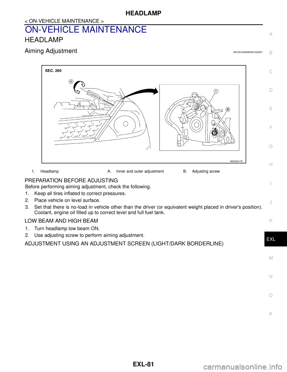
Aiming AdjustmentINFOID:0000000001529251
PREPARATION BEFORE ADJUSTING
Before performing aiming adjustment, check the following.
1. Keep all tires inflated to correct pressures.
2. Place vehicle on level surface.
3. Set that there is no-load in vehicle other than the driver (or equivalent weight placed in driver's position).
Coolant, engine oil filled up to correct level and full fuel tank.
LOW BEAM AND HIGH BEAM
1. Turn headlamp low beam ON.
2. Use adjusting screw to perform aiming adjustment.
ADJUSTMENT USING AN ADJUSTMENT SCREEN (LIGHT/DARK BORDERLINE)
1. Headlamp A. Inner and outer adjustment B. Adjusting screw
WKIA5417E
Page 3084 of 5883

FRONT FOG LAMP
EXL-83
< ON-VEHICLE MAINTENANCE >
C
D
E
F
G
H
I
J
K
MA
B
EXL
N
O
P
FRONT FOG LAMP
Aiming AdjustmentINFOID:0000000001529283
The front fog lamp is a semi-sealed beam type which uses a replaceable halogen bulb. Before performing
aiming adjustment, make sure of the following.
Keep all tires inflated to correct pressure.
Place vehicle on level surface.
Set that there is no-load in vehicle other than the driver (or equivalent weight placed in driver’s position).
Coolant, engine oil filled up to correct level and full fuel tank.
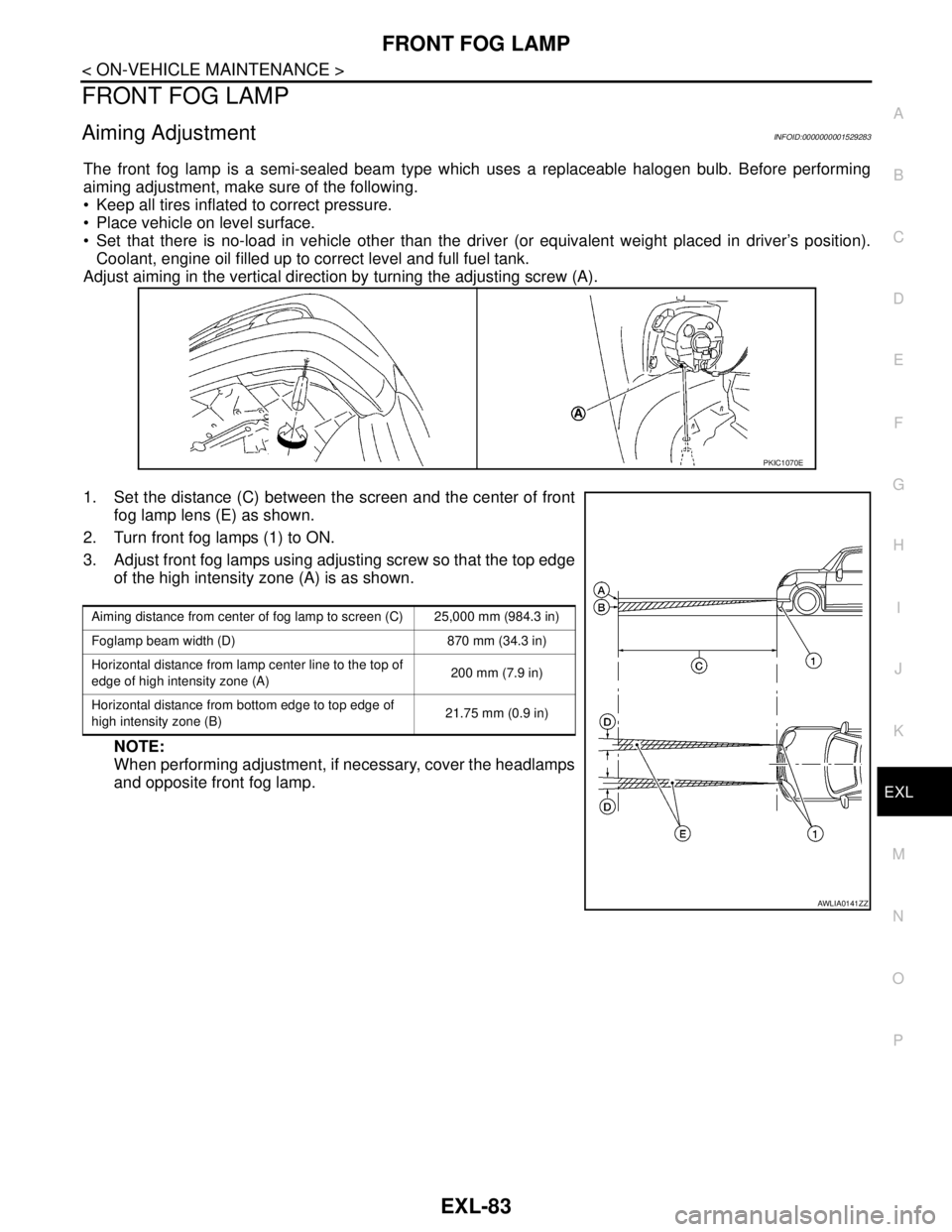
Adjust aiming in the vertical direction by turning the adjusting screw (A).
1. Set the distance (C) between the screen and the center of front
fog lamp lens (E) as shown.
2. Turn front fog lamps (1) to ON.
3. Adjust front fog lamps using adjusting screw so that the top edge
of the high intensity zone (A) is as shown.
NOTE:
When performing adjustment, if necessary, cover the headlamps
and opposite front fog lamp.
PKIC1070E
Aiming distance from center of fog lamp to screen (C) 25,000 mm (984.3 in)
Foglamp beam width (D) 870 mm (34.3 in)
Horizontal distance from lamp center line to the top of
edge of high intensity zone (A)200 mm (7.9 in)
Horizontal distance from bottom edge to top edge of
high intensity zone (B)21.75 mm (0.9 in)
AWLIA0141ZZ
Page 3182 of 5883

FSU-6
< ON-VEHICLE MAINTENANCE >
FRONT SUSPENSION ASSEMBLY
ON-VEHICLE MAINTENANCE
FRONT SUSPENSION ASSEMBLY
On-Vehicle Inspection and ServiceINFOID:0000000001716890
Make sure the mounting conditions (looseness, back lash) of each component and component conditions
(wear, damage) are normal.
INSPECTION OF LOWER BALL JOINT END PLAY
1. Set front wheels in a straight-ahead position. Do not depress brake pedal.
2. Place an iron bar or similar tool between transverse link and steering knuckle.
3. Measure axial end play by prying it up and down.
CAUTION:
Be careful not to damage ball joint boot. Do not damage the installation position by applying
excessive force.
STRUT INSPECTION
Check for oil leakage, damage and replace as necessary.
Wheel Alignment InspectionINFOID:0000000001716891
PRELIMINARY INSPECTION
WARNING:
Always adjust the alignment with the vehicle on a flat surface.
NOTE:
If alignment is out of specification, inspect and replace any damaged or worn rear suspension parts before
making any adjustments.
1. Check and adjust the wheel alignment with the vehicle under unladen conditions. “Unladen conditions”
means that the fuel, coolant, and lubricant are full; and that the spare tire, jack, hand tools and mats are in
their designated positions.
2. Check the tires for incorrect air pressure and excessive wear.
3. Check the wheels for run out and damage. Refer to WT-5, "
Inspection" .
4. Check the wheel bearing axial end play. Refer to FA X - 5 , "
On-Vehicle Inspection and Service" .
5. Check the shock absorbers for leaks or damage.
6. Check each mounting point of the suspension components for any excessive looseness or damage.
7. Check each link, arm, and the suspension member for any damage.
8. Check the vehicle height. Refer to FSU-18, "
Wheelarch Height (Unladen*)" .
GENERAL INFORMATION AND RECOMMENDATIONS
1. A Four-Wheel Thrust Alignment should be performed.
This type of alignment is recommended for any NISSAN vehicle.
The four-wheel “thrust” process helps ensure that the vehicle is properly aligned and the steering wheel
is centered.
The alignment machine itself should be capable of accepting any NISSAN vehicle.
The alignment machine should be checked to ensure that it is level.
2. Make sure the alignment machine is properly calibrated.
Your alignment machine should be regularly calibrated in order to give correct information.
Check with the manufacturer of your specific alignment machine for their recommended Service/Cali-
bration Schedule.
THE ALIGNMENT PROCESS
IMPORTANT: Use only the alignment specifications listed in this Service Manual. Refer to FSU-17, "Wheel
Alignment (Unladen*)" .
1. When displaying the alignment settings, many alignment machines use “indicators”: (Green/red, plus or
minus, Go/No Go). Do NOT use these indicators. Axial end play : 0 mm (0 in)
Page 3283 of 5883

HA-1
VENTILATION, HEATER & AIR CONDITIONER
C
D
E
F
G
H
J
K
L
M
SECTION HA
A
B
HA
N
O
P
CONTENTS
HEATER & AIR CONDITIONING SYSTEM
PRECAUTION ...............................................3
PRECAUTIONS ...................................................3
Precaution for Supplemental Restraint System
(SRS) "AIR BAG" and "SEAT BELT PRE-TEN-
SIONER" ...................................................................
3
Precaution for Procedure without Cowl Top Cover ......3
Precaution for Working with HFC-134a (R-134a) ......3
General Refrigerant Precaution ................................4
Oil Precaution ............................................................4
Precaution for Refrigerant Connection ......................4
Precaution for Service of Compressor ......................8
Precaution for Service Equipment .............................9
Precaution for Leak Detection Dye .........................10
PREPARATION ...........................................12
PREPARATION ..................................................12
HFC-134a (R-134a) Service Tool and Equipment ....12
Commercial Service Tool ........................................14
FUNCTION DIAGNOSIS ..............................16
REFRIGERATION SYSTEM ..............................16
Refrigerant Cycle ....................................................16
Refrigerant System Protection ................................16
OIL ......................................................................18
Maintenance of Oil Quantity in Compressor ...........18
ON-VEHICLE MAINTENANCE ....................19
OIL ......................................................................19
Maintenance of Oil Quantity in Compressor ...........19
REFRIGERATION SYSTEM ..............................21
HFC-134a (R-134a) Service Procedure ..................21
Checking of Refrigerant Leaks ................................22
FLUORESCENT LEAK DETECTOR .................24
Checking System for Leaks Using the Fluorescent
Leak Detector ..........................................................
24
Dye Injection ............................................................24
ELECTRICAL LEAK DETECTOR ....................25
Electronic Refrigerant Leak Detector .......................25
ON-VEHICLE REPAIR .................................27
REFRIGERATION SYSTEM .............................27
Component ..............................................................27
HFC-134a (R-134a) Service Procedure ..................29
COMPRESSOR .................................................32
Removal and Installation of Compressor -
MR18DE ..................................................................
32
Removal and Installation of Compressor -
HR16DE ..................................................................
34
Removal and Installation of Compressor - K9K .......35
LOW-PRESSURE FLEXIBLE HOSE ................38
Removal and Installation of Low-Pressure Flexi-
ble Hose - MR18DE, HR16DE ................................
38
Removal and Installation of Low-Pressure Flexi-
ble Hose - K9K ........................................................
38
LOW-PRESSURE PIPE ....................................40
Removal and Installation of Low-Pressure Pipe -
K9K ..........................................................................
40
HIGH-PRESSURE FLEXIBLE HOSE ...............41
Removal and Installation of High-Pressure Flexi-
ble Hose - MR18DE, HR16DE ................................
41
Removal and Installation of High-Pressure Flexi-
ble Hose - K9K ........................................................
41
HIGH-PRESSURE PIPE ....................................43
Removal and Installation of High-Pressure Pipe -
MR18DE, HR16DE ..................................................
43
Removal and Installation of High-Pressure Pipe -
K9K ..........................................................................
43
CONDENSER ....................................................45
Removal and Installation of Condenser -
MR18DE, HR16DE ..................................................
45
Page 3286 of 5883

HA-4
< PRECAUTION >
PRECAUTIONS
General Refrigerant Precaution
INFOID:0000000001396430
WARNING:
Avoid breathing A/C refrigerant and oil vapor or mist. Exposure may irritate eyes, nose and throat.
Use only approved recovery/recycling equipment to discharge HFC-134a (R-134a) refrigerant. If acci-
dental system discharge occurs, ventilate work area before resuming service. Additional health and
safety information may be obtained from refrigerant and oil manufacturers.
Do not release refrigerant into the air. Use approved recovery/recycling equipment to capture the
refrigerant every time an air conditioning system is discharged.
Always wear eye and hand protection (goggles and gloves) when working with any refrigerant or air
conditioning system.
Do not store or heat refrigerant containers above 52°C (126° F).
Do not heat a refrigerant container with an open flame; if container warming is required, place the
bottom of the container in a warm pail of water.
Do not intentionally drop, puncture, or incinerate refrigerant containers.
Keep refrigerant away from open flames: poisonous gas will be produced if refrigerant burns.
Refrigerant will displace oxygen, therefore be certain to work in well ventilated areas to prevent suf-
focation.
Do not pressure test or leak test HFC-134a (R-134a) service equipment and/or vehicle air condition-
ing systems with compressed air during repair. Some mixtures of air and HFC-134a (R-134a) have
been shown to be combustible at elevated pressures. These mixtures, if ignited, may cause injury or
property damage. Additional health and safety information may be obtained from refrigerant manu-
facturers.
Oil PrecautionINFOID:0000000001396431
Use only specified oil for the HFC-134a (R-134a) A/C system and HFC-134a (R-134a) components. If oil
other than that specified is used, compressor malfunction is likely to occur.
The specified HFC-134a (R-134a) oil rapidly absorbs moisture from the atmosphere. The following handling
precautions must be observed:
- When removing refrigerant components from a vehicle, immediately cap (seal) the component to minimize
the entry of moisture from the atmosphere.
- When installing refrigerant components to a vehicle, do not remove the caps (unseal) until just before con-
necting the components. Connect all refrigerant loop components as quickly as possible to minimize the
entry of moisture into system.
- Only use the specified oil from a sealed container. Immediately reseal containers of oil. Without proper seal-
ing, oil will become moisture saturated and should not be used.
Avoid breathing A/C refrigerant and oil vapor or mist. Exposure may irritate eyes, nose and throat.
Use only approved recovery/recycling equipment to discharge HFC-134a (R-134a) refrigerant. If accidental
system discharge occurs, ventilate work area before resuming service. Additional health and safety informa-
tion may be obtained from refrigerant and oil manufacturers.
Do not allow A/C oil to come in contact with styrofoam parts. Damage may result.
Precaution for Refrigerant ConnectionINFOID:0000000001396432
A new type refrigerant connection has been introduced to all refrigerant lines except the following location.
Expansion valve to evaporator
Refrigerant pressure sensor to condenser