Page 41 of 116

AUDIO
AV-41
C
D
E
F
G
H
I
J
L
MA
B
AV
Revision: 2006 November2007 350Z
Power Supply Circuit InspectionNKS002BF
1. CHECK FUSE
Make sure that the following fuses of the audio unit, BOSE speaker amp. and woofer amp. are not blown.
OK or NG
OK >> GO TO 2.
NG >> If fuse is blown, be sure to eliminate cause of malfunction before installing new fuse. Refer to PG-
4, "POWER SUPPLY ROUTING CIRCUIT" .
2. CHECK POWER SUPPLY CIRCUIT
1. Check voltage between audio unit harness connector terminals
and ground.
2. Check voltage between BOSE speaker amp., woofer amp. har-
ness connector terminals and ground (BOSE system).
OK or NG
OK >>�INSPECTION END (Base system)
�GO TO 3 (BOSE system).
NG >> Repair harness or connector.
Unit Signal Fuse No.
Audio unitBattery power supply 37
Ignition switch ACC or ON 6
BOSE speaker amp. Battery power supply 37
Woofer amp. Battery power supply 17
UnitTerminals
OFF ACC ON (+)
(–)
Connector Terminal
Audio
unitM406GroundBattery
voltageBattery
voltageBattery
voltage
10 Ground 0 VBattery
voltageBattery
voltage
SKIA8743E
UnitTerminals
OFF ACC ON (+)
(–)
Connector Terminal
BOSE
speaker
amp.T6 11
GroundBattery
voltageBattery
voltageBattery
voltage
Woofer
amp.B32 8
SKIA8744E
Page 42 of 116

AV-42
AUDIO
Revision: 2006 November2007 350Z
3. CHECK GROUND CIRCUIT
1. Turn ignition switch OFF.
2. Disconnect BOSE speaker amp. and woofer amp. connectors.
3. Check continuity between BOSE speaker amp. harness connec-
tor T6 terminal 27 and ground.
4. Check continuity between woofer amp. harness connector B32
terminal 7 and ground.
OK or NG
OK >> INSPECTION END
NG >> Repair harness or connector.
Steering Switch Does Not OperateNKS002EE
1. CHECK STEERING SWITCH RESISTANCE
1. Turn ignition switch OFF.
2. Disconnect combination switch (spiral cable) connector.
3. Check resistance between steering switch harness connector
M203 terminals.
OK or NG
OK >> GO TO 2.
NG >> Replace steering switch.
2. CHECK SPIRAL CABLE
1. Disconnect combination switch (spiral cable) connector.
2. Check continuity between combination switch (spiral cable) con-
nector (A) terminals 16, 17, 20 and connector (B) terminals 32,
31, 24.
OK or NG
OK >> GO TO 3.
NG >> Replace spiral cable.27 – Ground : Continuity should exist.
7 – Ground : Continuity should exist.
SKIA8745E
Terminal Signal name Condition Resistance (Ω)
16
17Power Press and hold POWER switch. Approx. 0
Seek downPress and hold SEEK DOWN
switch.Approx. 165
Vo l u m e d o wnPress and hold VOLUME DOWN
switch.Approx. 652
20Mode Press and hold MODE switch. Approx. 0
Seek up Press and hold SEEK UP switch. Approx. 165
Vo l u m e u pPress and hold VOLUME UP
switch.Approx. 652
SKIB7339E
16 – 32 : Continuity should exist.
17 – 31 : Continuity should exist.
20 – 24 : Continuity should exist.
SKIB7340E
Page 43 of 116
 M46")
AUDIO
AV-43
C
D
E
F
G
H
I
J
L
MA
B
AV
Revision: 2006 November2007 350Z
3. CHECK HARNESS
Base system
1. Disconnect audio unit connector.
2. Check continuity between audio unit harness connector (A) M46
terminals 21, 22, 23 and combination switch (spiral cable) har-
ness connector (B) M23 terminals 24, 32, 31.
3. Check continuity between audio unit harness connector (A) M46
terminals 21, 22 and ground.
BOSE system
1. Disconnect audio unit connector.
2. Check continuity between audio unit harness connector (A) M39
terminals 22, 23, 25 and combination switch (spiral cable) har-
ness connector (B) M23 terminals 24, 32, 31.
3. Check continuity between audio unit harness connector (A) M39
terminals 22, 23 and ground.
OK or NG
OK >> Replace audio unit.
NG >> Repair harness or connector.21 – 24 : Continuity should exist.
22 – 32 : Continuity should exist.
23 – 31 : Continuity should exist.
21, 22 – Ground : Continuity should not exist.
SKIB7341E
22 – 24 : Continuity should exist.
23 – 32 : Continuity should exist.
25 – 31 : Continuity should exist.
22, 23 – Ground : Continuity should not exist.
SKIB7342E
Page 44 of 116

AV-44
AUDIO
Revision: 2006 November2007 350Z
AudioPilot® Does Not WorkNKS002BG
1. CHECK AUDIO UNIT
Check AudioPilot
® turns ON.
OK or NG
OK >> GO TO 2.
NG >> Turn AudioPilot® ON.
2. CHECK HARNESS
1. Turn ignition switch OFF.
2. Disconnect audio unit and BOSE speaker amp. connectors.
3. Check continuity between audio unit harness connector M39 ter-
minal 17 and BOSE speaker amp. harness connector T7 termi-
nal 31.
4. Check continuity between audio unit harness connector M39 ter-
minal 17 and ground.
OK or NG
OK >> GO TO 3.
NG >> Repair harness or connector.
3. CHECK AUDIOPILOT® SIGNAL
1. Connect audio unit and BOSE speaker amp. connectors.
2. Turn ignition switch ON.
3. Check voltage between audio unit harness connector terminals
and ground.
OK or NG
OK >> GO TO 4.
NG >> Replace audio unit.17 – 31 : Continuity should exist.
17 – Ground : Continuity should not exist.
SKIA8019E
Te r m i n a l s
Condition Voltage (+)
(–)
Connector Terminal
M39 17 GroundAudioPilot
® OFFApprox. 7.5 V
AudioPilot
® ONApprox. 0 V
SKIA8020E
Page 45 of 116

AUDIO
AV-45
C
D
E
F
G
H
I
J
L
MA
B
AV
Revision: 2006 November2007 350Z
4. CHECK HARNESS
1. Turn ignition switch OFF
2. Disconnect BOSE speaker amp. and microphone connectors.
3. Check continuity between BOSE speaker amp. harness connec-
tor T7 terminal 17 and microphone harness connector E123 ter-
minal 1.
4. Check continuity between BOSE speaker amp. harness connec-
tor T7 terminal 17 and ground.
OK or NG
OK >> GO TO 5.
NG >> Repair harness or connector.
5. CHECK HARNESS
1. Check continuity between BOSE speaker amp. harness connec-
tor T7 terminal 18 and microphone harness connector E123 ter-
minal 2.
2. Check continuity between BOSE speaker amp. harness connec-
tor T7 terminal 18 and ground.
OK or NG
OK >> GO TO 6.
NG >> Repair harness or connector.
6. CHECK MICROPHONE SIGNAL
1. Connect BOSE speaker amp. and microphone connectors.
2. Turn ignition switch ON.
3. Check voltage waveform between BOSE speaker amp. harness
connector T7 terminal 17 and 18 using oscilloscope, when input-
ting some sounds (voice, etc.) toward the microphone.
Does the voltage waveform change with sounds?
YES >> Replace BOSE speaker amp.
NO >> Replace microphone.17 – 1 : Continuity should exist.
17 – Ground : Continuity should not exist.
SKIA3105E
18 – 2 : Continuity should exist.
18 – Ground : Continuity should not exist.
SKIA3106E
17 – 18:
SKIA3104EPKIA2104E
Page 46 of 116
NKS002BH
REMOVAL
1. Remove cluster lid C. Refer to IP-10, \"INSTRUMENT PANEL ASSEMBLY\" .
2. Remove screw")
AV-46
AUDIO
Revision: 2006 November2007 350Z
Removal and Installation of Audio Unit (Base system)NKS002BH
REMOVAL
1. Remove cluster lid C. Refer to IP-10, "INSTRUMENT PANEL ASSEMBLY" .
2. Remove screws (A), and remove audio unit (1).
3. Remove screws (8), and remove bracket.
INSTALLATION
Installation is the reverse order of removal.
Locking CD Auto Changer Mechanism (Audio unit of BOSE system)NKS002BI
CAUTION:
�Prior to removing a malfunctioning CD auto changer unit (Audio unit of BOSE system) that will be
shipped for repair, the changer mechanism MUST BE LOCKED to prevent the mechanism from
being damaged during shipping.
�If a CD is jammed or unable to be removed from the unit, do NOT lock the changer mechanism. If
the unit is to be shipped for repair, carefully package the unit to prevent vibration and shock.
DAMPER LOCK PROCEDURE
1. Eject and remove any CDs from the audio unit (BOSE system).
2. Turn ignition switch OFF. Wait until audio unit (BOSE system) display is off and mechanism stops moving
(mechanism sound stops).
3. Press any one of the disc selection buttons once. When a display shows on the audio unit (BOSE sys-
tem), press the same disc selection button again within 5 seconds.
�The changer mechanism will lock itself within 10 seconds.
4. After mechanism stops moving (mechanism sound stops), open the driver and passenger window, and
then disconnect negative battery cable.
CAUTION:
After the battery cables are disconnected, do not open/close the driver and/or front passenger door
with the window in the full up position. The automatic window adjusting function will not work and the
side roof panel may be damaged.
NOTE:
After installing a new or remanufactured audio unit (BOSE system), switching the audio unit (BOSE system)
ON will automatically unlock the mechanism. A special unlocking procedure is not required.
SKIB7343E
PKIA1765E
Page 47 of 116
AUDIO
AV-47
C
D
E
F
G
H
I
J
L
MA
B
AV
Revision: 2006 November2007 350Z
Removal and Installation of Audio Unit (BOSE system)NKS002BJ
REMOVAL
1. Perform damper lock operation. Refer to AV- 4 6 , "Locking CD Auto Changer Mechanism (Audio unit of
BOSE system)" .
2. Remove cluster lid C. Refer to IP-10, "
INSTRUMENT PANEL ASSEMBLY" .
3. Remove screws (A), and remove audio unit (1).
4. Remove screws (8), and remove bracket.
CAUTION:
�When carrying audio unit body, do not touch internal
mechanism access from cassette tape slot.
�Be careful not to allow foreign matter from cassette tape
slot.
INSTALLATION
Installation is the reverse order of removal.
Removal and Installation of Door Speaker NKS002BK
REMOVAL
1. Remove door finisher. Refer to EI-33, "Removal and Installation" .
2. Remove screws (3), and remove door speaker.
INSTALLATION
Installation is the reverse order of removal.
SKIB7343E
PKIA1767E
PKIA1768E
Page 48 of 116
AV-48
AUDIO
Revision: 2006 November2007 350Z
Removal and Installation of Rear Speaker NKS002BL
REMOVAL
1. Remove luggage floor finisher upper (front) (Coupe models), or luggage floor finisher upper (Roadster
models). Refer to EI-39, "
Removal and Installation (for Coupe Models)" , or EI-41, "Removal and Installa-
tion (for Roadster Models)" .
2. Remove screws (4), and remove rear speaker.
INSTALLATION
Installation is the reverse order of removal.
Removal and Installation of Tweeter NKS002BM
REMOVAL
1. Remove corner cover inner. Refer to GW-81, "Removal and Installation" .
2. Remove screws (2), and remove tweeter from corner cover
inner.
INSTALLATION
Installation is the reverse order of removal.
PKIA1770E
PKIA1772E
 1
1 2
2 3
3 4
4 5
5 6
6 7
7 8
8 9
9 10
10 11
11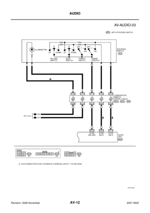 12
12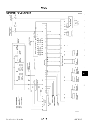 13
13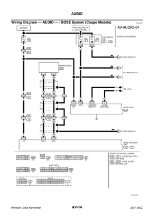 14
14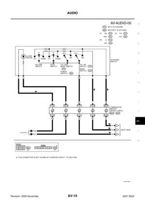 15
15 16
16 17
17 18
18 19
19 20
20 21
21 22
22 23
23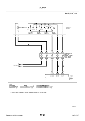 24
24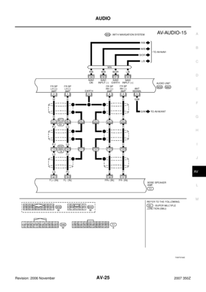 25
25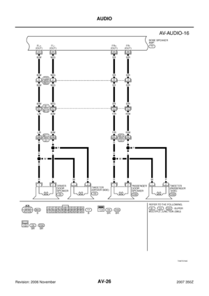 26
26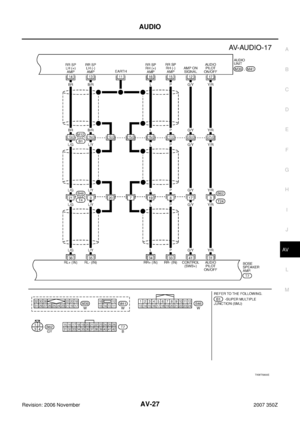 27
27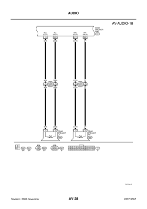 28
28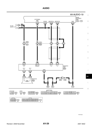 29
29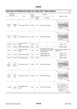 30
30 31
31 32
32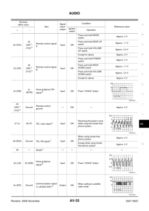 33
33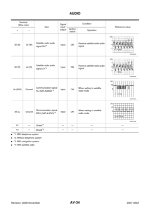 34
34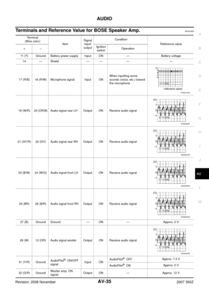 35
35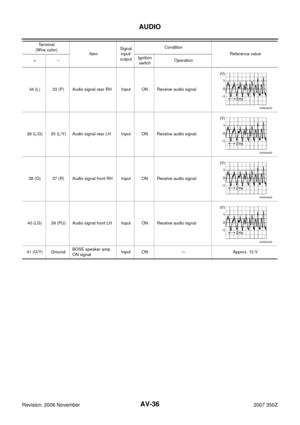 36
36 37
37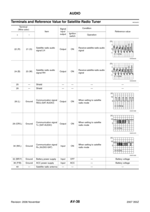 38
38 39
39 40
40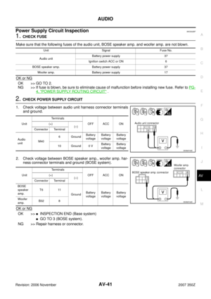 41
41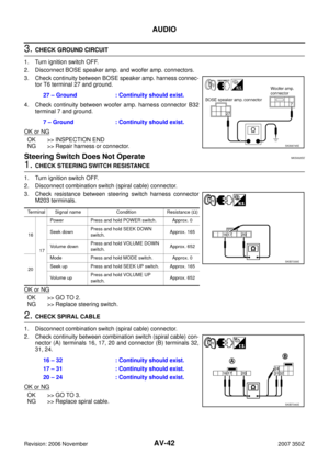 42
42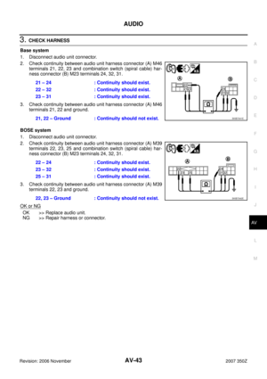 43
43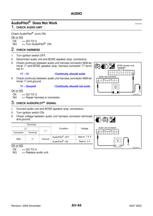 44
44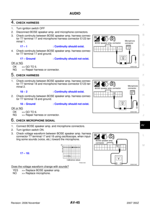 45
45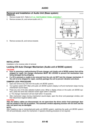 46
46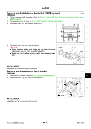 47
47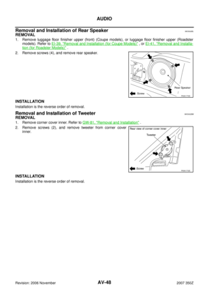 48
48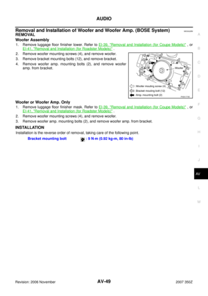 49
49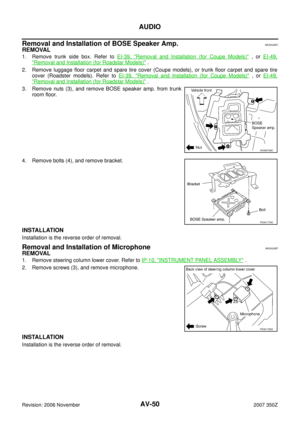 50
50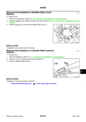 51
51 52
52 53
53 54
54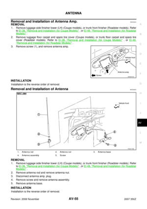 55
55 56
56 57
57 58
58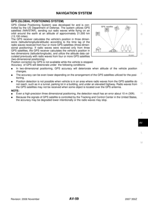 59
59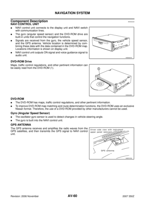 60
60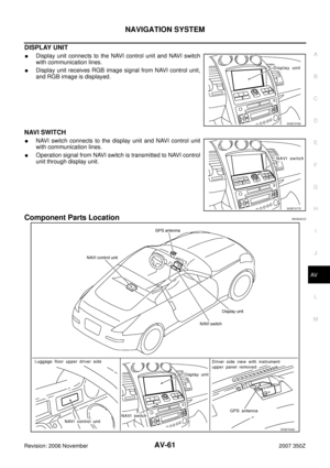 61
61 62
62 63
63 64
64 65
65 66
66 67
67 68
68 69
69 70
70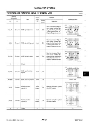 71
71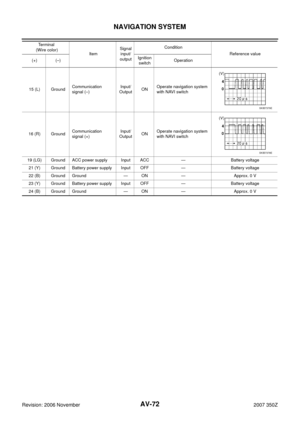 72
72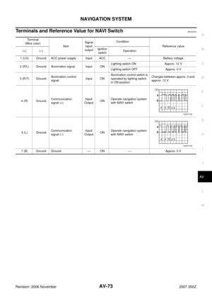 73
73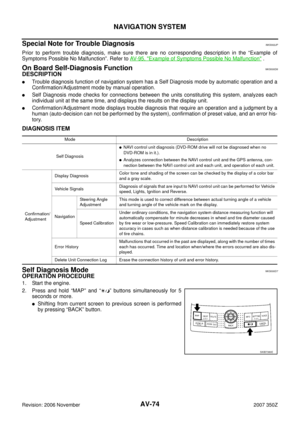 74
74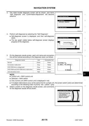 75
75 76
76 77
77 78
78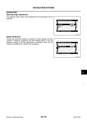 79
79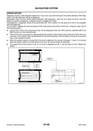 80
80 81
81 82
82 83
83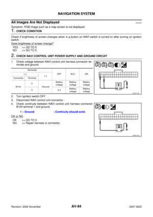 84
84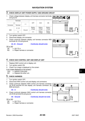 85
85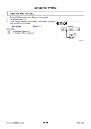 86
86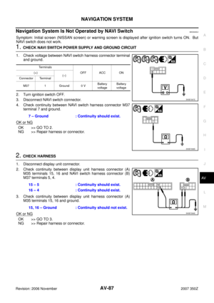 87
87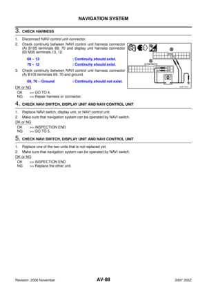 88
88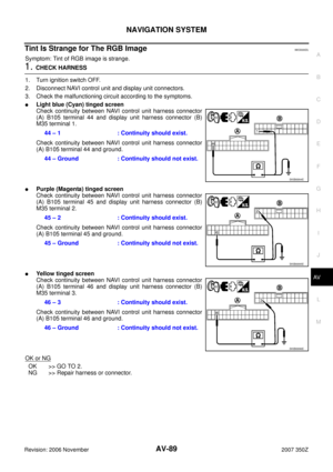 89
89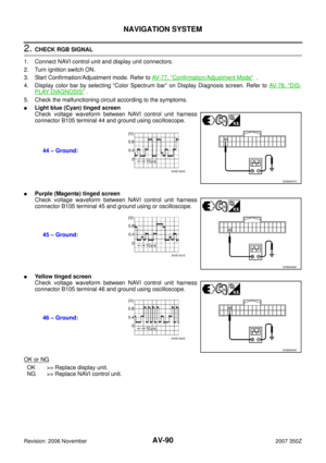 90
90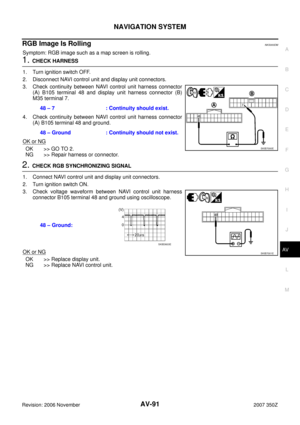 91
91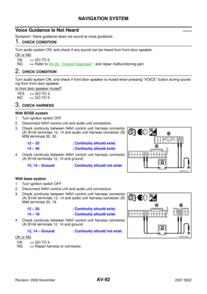 92
92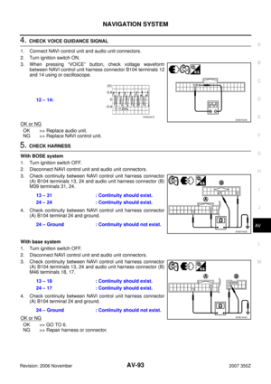 93
93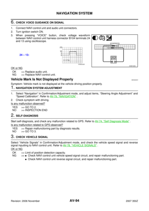 94
94 95
95 96
96 97
97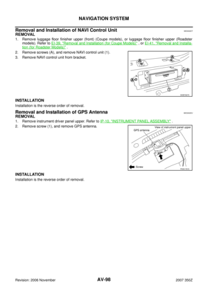 98
98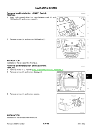 99
99 100
100 101
101 102
102 103
103 104
104 105
105 106
106 107
107 108
108 109
109 110
110 111
111 112
112 113
113 114
114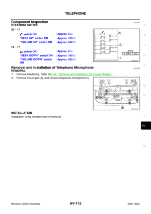 115
115NKS002BJ
REMOVAL
1. Perform damper lock operation. Refer to AV- 4 6 , \"Locki")
 (Coupe models), or luggage floor finisher upper (R")