Page 1 of 116

AV-1
AUDIO VISUAL, NAVIGATION & TELEPHONE SYS-
TEM
K ELECTRICAL
CONTENTS
C
D
E
F
G
H
I
J
L
M
SECTION AV
A
B
AV
Revision: 2006 November2007 350Z
AUDIO VISUAL, NAVIGATION & TELEPHONE SYSTEM
PRECAUTIONS .......................................................... 3
Precautions for Supplemental Restraint System
(SRS) “AIR BAG” and “SEAT BELT PRE-TEN-
SIONER” .................................................................. 3
Precautions for Battery Service ................................ 3
PREPARATION ........................................................... 4
Commercial Service Tools ........................................ 4
AUDIO ......................................................................... 5
System Description .................................................. 5
BASE SYSTEM ..................................................... 5
BOSE SYSTEM (COUPE MODELS) .................... 5
BOSE SYSTEM (ROADSTER MODELS) ............. 6
Component Parts Location ....................................... 8
Schematic / Base System ........................................ 9
Wiring Diagram — AUDIO — / Base System ......... 10
Schematic / BOSE System .................................... 13
Wiring Diagram — AUDIO — / BOSE System
(Coupe Models) ...................................................... 14
Wiring Diagram — AUDIO — / BOSE System
(Roadster Models) .................................................. 23
Terminals and Reference Value for Audio Unit / Base
System ................................................................... 30
Terminals and Reference Value for Audio Unit /
BOSE System ........................................................ 32
Terminals and Reference Value for BOSE Speaker
Amp. ....................................................................... 35
Terminals and Reference Value for Woofer Amp. ... 37
Terminals and Reference Value for Satellite Radio
Tuner ...................................................................... 38
Trouble Diagnosis .................................................. 39
Power Supply Circuit Inspection ............................ 41
Steering Switch Does Not Operate ........................ 42
AudioPilot® Does Not Work ................................... 44
Removal and Installation of Audio Unit (Base sys-
tem) ........................................................................ 46
REMOVAL ........................................................... 46
INSTALLATION ................................................... 46
Locking CD Auto Changer Mechanism (Audio unit
of BOSE system) .................................................... 46
DAMPER LOCK PROCEDURE .......................... 46Removal and Installation of Audio Unit (BOSE sys-
tem) ........................................................................ 47
REMOVAL ........................................................... 47
INSTALLATION ................................................... 47
Removal and Installation of Door Speaker ............. 47
REMOVAL ........................................................... 47
INSTALLATION ................................................... 47
Removal and Installation of Rear Speaker ............. 48
REMOVAL ........................................................... 48
INSTALLATION ................................................... 48
Removal and Installation of Tweeter ...................... 48
REMOVAL ........................................................... 48
INSTALLATION ................................................... 48
Removal and Installation of Woofer and Woofer
Amp. (BOSE System) ............................................. 49
REMOVAL ........................................................... 49
INSTALLATION ................................................... 49
Removal and Installation of BOSE Speaker Amp. ... 50
REMOVAL ........................................................... 50
INSTALLATION ................................................... 50
Removal and Installation of Microphone ................ 50
REMOVAL ........................................................... 50
INSTALLATION ................................................... 50
Removal and Installation of Satellite Radio Tuner ... 51
REMOVAL ........................................................... 51
INSTALLATION ................................................... 51
Removal and Installation of Satellite Radio Antenna ... 51
REMOVAL ........................................................... 51
INSTALLATION ................................................... 51
ANTENNA ................................................................. 52
System Description ................................................. 52
Wiring Diagram — M/ANT — ................................. 53
Location of Antenna ................................................ 54
Removal and Installation of Antenna Amp. ............ 55
REMOVAL ........................................................... 55
INSTALLATION ................................................... 55
Removal and Installation of Antenna ...................... 55
REMOVAL ........................................................... 55
INSTALLATION ................................................... 55
Removal and Installation of Satellite Radio Antenna ... 56
Page 2 of 116

AV-2Revision: 2006 November2007 350Z NAVIGATION SYSTEM ............................................. 57
System Description ................................................. 57
LOCATION DETECTION PRINCIPLE ................. 57
MAP-MATCHING ................................................. 58
GPS (GLOBAL POSITIONING SYSTEM) ........... 59
Component Description .......................................... 60
NAVI CONTROL UNIT ........................................ 60
GPS ANTENNA ................................................... 60
DISPLAY UNIT .................................................... 61
NAVI SWITCH ..................................................... 61
Component Parts Location ..................................... 61
Schematic ............................................................... 62
Wiring Diagram — NAVI — ..................................... 63
Wiring Diagram — COMM — ................................. 67
Terminals and Reference Value for NAVI Control
Unit ......................................................................... 69
Terminals and Reference Value for Display Unit .... 71
Terminals and Reference Value for NAVI Switch .... 73
Special Note for Trouble Diagnosis ........................ 74
On Board Self-Diagnosis Function ......................... 74
DESCRIPTION .................................................... 74
DIAGNOSIS ITEM ............................................... 74
Self Diagnosis Mode ............................................... 74
OPERATION PROCEDURE ................................ 74
SELF-DIAGNOSIS RESULT ............................... 76
Confirmation/Adjustment Mode .............................. 77
OPERATION PROCEDURE ................................ 77
DISPLAY DIAGNOSIS ......................................... 78
VEHICLE SIGNALS ............................................. 78
NAVIGATION ....................................................... 79
ERROR HISTORY ............................................... 80
DELETE UNIT CONNECTION LOG ................... 83
All Images Are Not Displayed ................................. 84
Navigation System Is Not Operated by NAVI Switch ... 87
Tint Is Strange for The RGB Image ........................ 89
RGB Image Is Rolling ............................................. 91
Voice Guidance Is Not Heard ................................. 92
Vehicle Mark Is Not Displayed Properly ................. 94
Example of Symptoms Possible No Malfunction .... 95BASIC OPERATIONS .......................................... 95
VEHICLE MARKS ................................................ 95
DVD-ROM ............................................................ 96
ROUTE CALCULATION AND VISUAL GUID-
ANCE ................................................................... 96
VOICE GUIDANCE .............................................. 97
Removal and Installation of NAVI Control Unit ........ 98
REMOVAL ............................................................ 98
INSTALLATION .................................................... 98
Removal and Installation of GPS Antenna .............. 98
REMOVAL ............................................................ 98
INSTALLATION .................................................... 98
Removal and Installation of NAVI Switch ................ 99
REMOVAL ............................................................ 99
INSTALLATION .................................................... 99
Removal and Installation of Display Unit ................ 99
REMOVAL ............................................................ 99
INSTALLATION .................................................... 99
TELEPHONE ...........................................................100
System Description ...............................................100
HANDS-FREE PHONE SYSTEM ......................100
Component Parts Location ...................................101
Location of TEL Antenna ......................................102
Schematic .............................................................103
Wiring Diagram — H/PHONE — ...........................104
Terminals and Reference Value for TEL Adapter
Unit ........................................................................110
Self-Diagnosis Function ........................................ 111
DIAGNOSIS FUNCTION OPERATION PROCE-
DURE .................................................................112
ERROR ITEM (ERROR NAME) .........................113
VEHICLE SPEED SIGNAL ................................113
MICROPHONE TEST ........................................113
Symptom Chart .....................................................114
Component Inspection ..........................................115
STEERING SWITCH .........................................115
Removal and Installation of Telephone Microphone .115
REMOVAL ..........................................................115
INSTALLATION ..................................................115
Page 3 of 116
 “AIR BAG” and “SEAT
BELT PRE-TENSIONER”
NK")
PRECAUTIONS
AV-3
C
D
E
F
G
H
I
J
L
MA
B
AV
Revision: 2006 November2007 350Z
PRECAUTIONSPFP:00001
Precautions for Supplemental Restraint System (SRS) “AIR BAG” and “SEAT
BELT PRE-TENSIONER”
NKS000C3
The Supplemental Restraint System such as “AIR BAG” and “SEAT BELT PRE-TENSIONER”, used along
with a front seat belt, helps to reduce the risk or severity of injury to the driver and front passenger for certain
types of collision. This system includes seat belt switch inputs and dual stage front air bag modules. The SRS
system uses the seat belt switches to determine the front air bag deployment, and may only deploy one front
air bag, depending on the severity of a collision and whether the front occupants are belted or unbelted.
Information necessary to service the system safely is included in the SRS and SB section of this Service Man-
ual.
WARNING:
�To avoid rendering the SRS inoperative, which could increase the risk of personal injury or death
in the event of a collision which would result in air bag inflation, all maintenance must be per-
formed by an authorized NISSAN/INFINITI dealer.
�Improper maintenance, including incorrect removal and installation of the SRS, can lead to per-
sonal injury caused by unintentional activation of the system. For removal of Spiral Cable and Air
Bag Module, see the SRS section.
�Do not use electrical test equipment on any circuit related to the SRS unless instructed to in this
Service Manual. SRS wiring harnesses can be identified by yellow and/or orange harnesses or
harness connectors.
Precautions for Battery ServiceNKS000C4
Before disconnecting the battery, lower both the driver and passenger windows. This will prevent any interfer-
ence between the window edge and the vehicle when the door is opened/closed. During normal operation, the
window slightly raises and lowers automatically to prevent any window to vehicle interference. The automatic
window function will not work with the battery disconnected.
Page 4 of 116
AV-4
PREPARATION
Revision: 2006 November2007 350Z
PREPARATIONPFP:00002
Commercial Service ToolsNKS000C6
Tool nameDescription
Power toolLoosening bolts and nuts
PBIC0191E
Page 5 of 116

AUDIO
AV-5
C
D
E
F
G
H
I
J
L
MA
B
AV
Revision: 2006 November2007 350Z
AUDIOPFP:28111
System DescriptionNKS000C7
BASE SYSTEM
For Audio System operation information, refer to Owner's Manual.
Power is supplied at all times
�through 15 A fuse [No. 37, located in the fuse and fusible link box]
�to audio unit terminal 6.
With the ignition switch in the ACC or ON position, power is supplied
�through 10 A fuse [No. 6, located in the fuse block (J/B)]
�to audio unit terminal 10.
Ground is supplied through the case of the audio unit.
When audio switch is pressed, audio signals are supplied
�through audio unit terminals 1, 2, 3, 4, 13, 14, 15 and 16
�to terminals 1 and 2 of driver door speaker and passenger door speaker
�to terminals 1 and 2 of rear speaker LH and RH
�to terminals 1 and 2 of tweeter (driver side) and tweeter (passenger side).
When one of steering switch is pressed to volume up, seek up, or mode ON, resistance in steering switch cir-
cuit changes depending on which button is pressed.
When one of steering switch is pressed to volume down, seek down, or power ON, resistance in steering
switch circuit changes depending on which button is pressed.
BOSE SYSTEM (COUPE MODELS)
CD auto changer (built into audio unit) operation is controlled by audio unit.
Refer to owner's manual for the system operation.
Power is supplied at all times
�through 15 A fuse [No. 37, located in the fuse and fusible link box]
�to audio unit terminal 6
�to BOSE speaker amp. terminal 11
�to satellite radio tuner terminal 32,
�through 15 A fuse [No. 17, located in the fuse block (J/B)]
�to woofer amp. terminal 8.
With the ignition switch in the ACC or ON position, power is supplied
�through 10 A fuse [No. 6, located in the fuse block (J/B)]
�to audio unit terminal 10
�to satellite radio tuner terminal 36,
�through audio unit terminal 12
�to BOSE speaker amp. terminal 41,
�through BOSE speaker amp. terminal 32
�to woofer amp. terminal 6.
Ground is supplied through the case of the audio unit.
Ground is also supplied
�to BOSE speaker amp. terminal 27
�to woofer amp. terminal 7
�through body grounds B5, B6, D105 and T14.
When audio switch is pressed, audio signals are supplied
�through audio unit terminals 1, 2, 3, 4, 13, 14, 15 and 16
�to BOSE speaker amp. terminals 33, 34, 35, 36, 37, 38, 39 and 40.
Audio signals are amplified by the BOSE speaker amp.
The amplified audio signals are supplied
�through BOSE speaker amp. terminals 12, 19, 20, 21, 22, 23, 24, 25, 26 and 28
�to terminals 1 and 2 of driver door speaker and passenger door speaker
Page 6 of 116
 and tweeter (passenger side)
�to terminals 1 and 2 of woofer")
AV-6
AUDIO
Revision: 2006 November2007 350Z
�to terminals 1 and 2 of rear speaker LH and RH
�to terminals 1 and 2 of tweeter (driver side) and tweeter (passenger side)
�to terminals 1 and 2 of woofer amp.
Audio signals are amplified by the woofer amp.
The amplified audio signals are supplied
�through woofer amp. terminals 3 and 4
�to terminals 1 and 2 of woofer.
When one of steering switch is pressed to volume up, seek up, or mode ON, resistance in steering switch cir-
cuit changes depending on which button is pressed.
When one of steering switch is pressed to volume down, seek down, or power ON, resistance in steering
switch circuit changes depending on which button is pressed.
BOSE SYSTEM (ROADSTER MODELS)
CD auto changer (built into audio unit) operation is controlled by audio unit.
Refer to owner's manual for the system operation.
Power is supplied at all times
�through 15 A fuse [No. 37, located in the fuse and fusible link box]
�to audio unit terminal 6
�to BOSE speaker amp. terminal 11,
�through 15 A fuse [No. 17, located in the fuse block (J/B)]
�to woofer amp. terminal 8.
With the ignition switch in the ACC or ON position, power is supplied
�through 10 A fuse [No. 6, located in the fuse block (J/B)]
�to audio unit terminal 10,
�through audio unit terminal 12
�to BOSE speaker amp. terminal 41,
�through BOSE speaker amp. terminal 32
�to woofer amp. terminal 6.
Ground is supplied through the case of the audio unit.
Ground is also supplied
�to BOSE speaker amp. terminal 27
�to woofer amp. terminal 7
�through body grounds B5, B6 and T14.
When audio switch is pressed, audio signals are supplied
�through audio unit terminals 1, 2, 3, 4, 13, 14, 15 and 16
�to BOSE speaker amp. terminals 33, 34, 35, 36, 37, 38, 39 and 40.
Audio signals are amplified by the BOSE speaker amp.
The amplified audio signals are supplied
�through BOSE speaker amp. terminals 12, 19, 20, 21, 22, 23, 24, 25, 26 and 28
�to terminals 1 and 2 of driver door speaker and passenger door speaker
�to terminals 1 and 2 of rear speaker LH and RH
�to terminals 1 and 2 of tweeter (driver side) and tweeter (passenger side)
�to terminals 1 and 2 of woofer amp.
Audio signals are amplified by the woofer amp.
The amplified audio signals are supplied
�through woofer amp. terminals 3 and 4
�to terminals 1 and 2 of woofer.
When one of steering switch is pressed to volume up, seek up, or mode ON, resistance in steering switch cir-
cuit changes depending on which button is pressed.
When one of steering switch is pressed to volume down, seek down, or power ON, resistance in steering
switch circuit changes depending on which button is pressed.
Page 7 of 116
AUDIO
AV-7
C
D
E
F
G
H
I
J
L
MA
B
AV
Revision: 2006 November2007 350Z
AudioPilot® System
AudioPilot® is the sound improving system that picks up by a microphone under the steering any noises or the
sound of music coming into the vehicle, and that uses the BOSE speaker amp. to revise the frequency feature
of music in real time in response to the frequency feature of the noise while driving and listening to music.
�If low frequency area noise from vehicle is loud, it adjusts low frequency element of music to be bigger
than vehicle noise.
�If high frequency area noise from vehicle is loud, it adjusts high frequency element of music to be bigger
than vehicle noise.
�If vehicle noise is smaller than the setting volume, correction is not performed.
Page 8 of 116
AV-8
AUDIO
Revision: 2006 November2007 350Z
Component Parts LocationNKS000C8
SKIB7335E
 1
1 2
2 3
3 4
4 5
5 6
6 7
7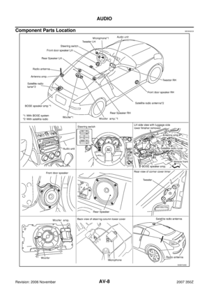 8
8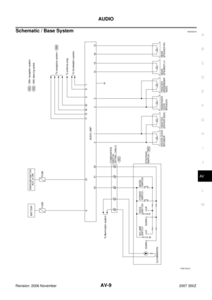 9
9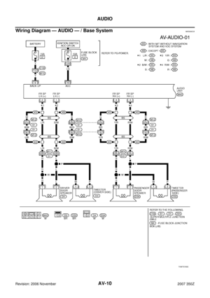 10
10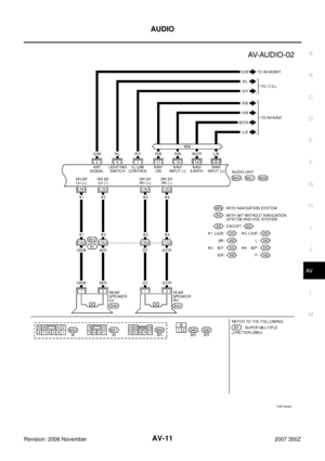 11
11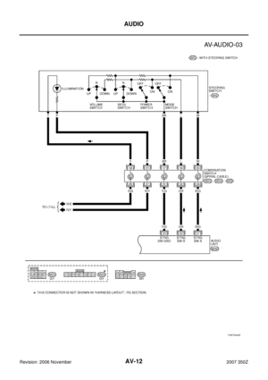 12
12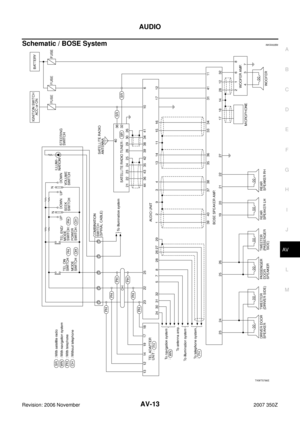 13
13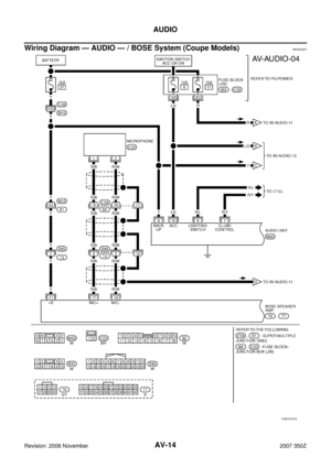 14
14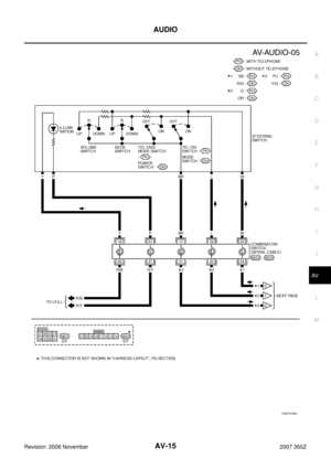 15
15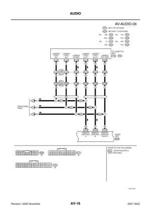 16
16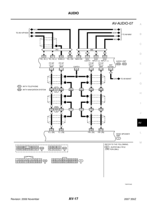 17
17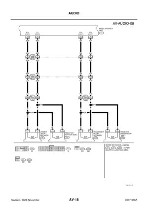 18
18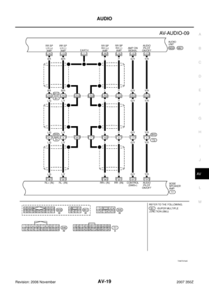 19
19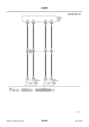 20
20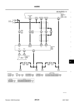 21
21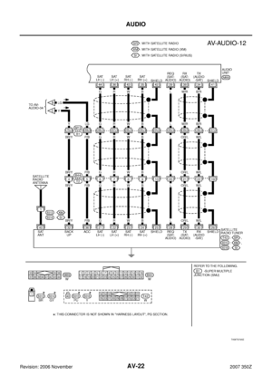 22
22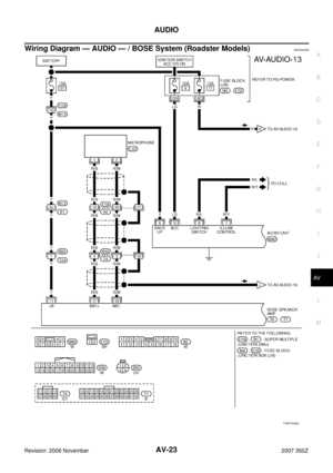 23
23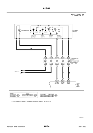 24
24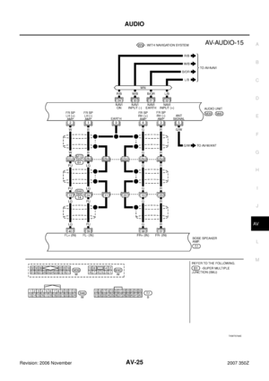 25
25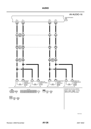 26
26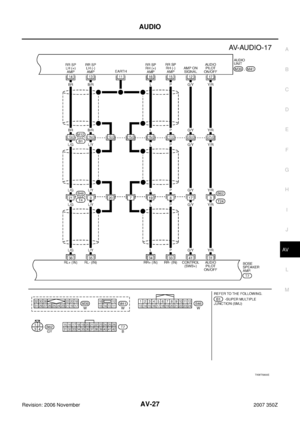 27
27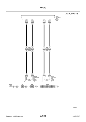 28
28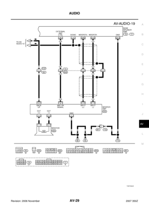 29
29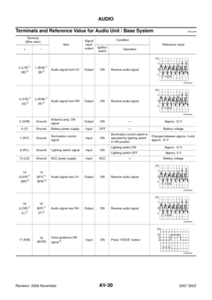 30
30 31
31 32
32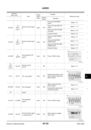 33
33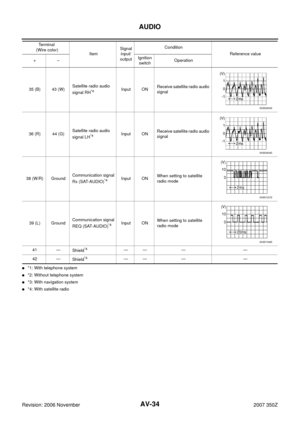 34
34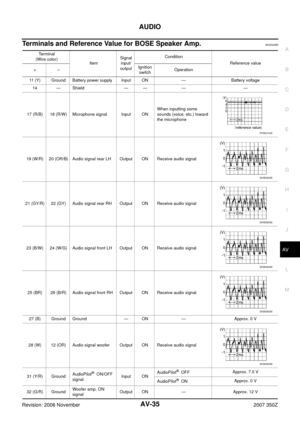 35
35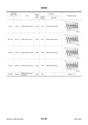 36
36 37
37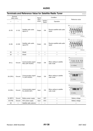 38
38 39
39 40
40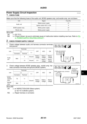 41
41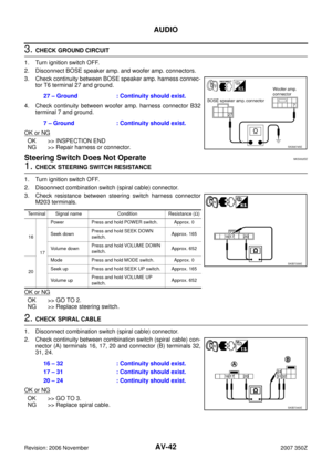 42
42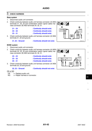 43
43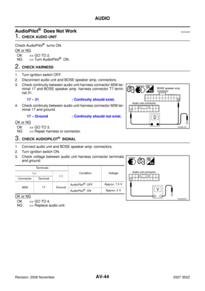 44
44 45
45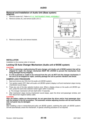 46
46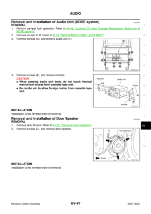 47
47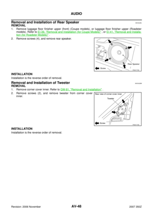 48
48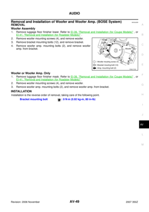 49
49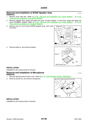 50
50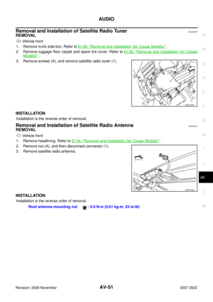 51
51 52
52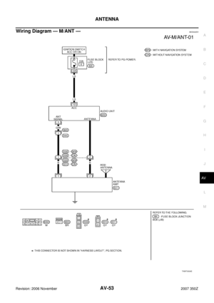 53
53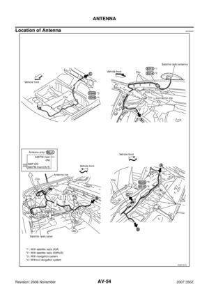 54
54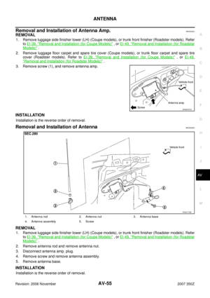 55
55 56
56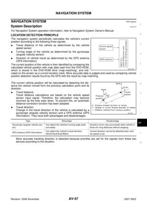 57
57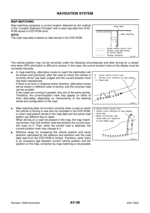 58
58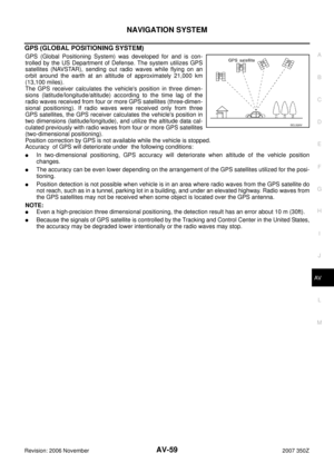 59
59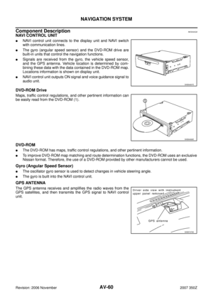 60
60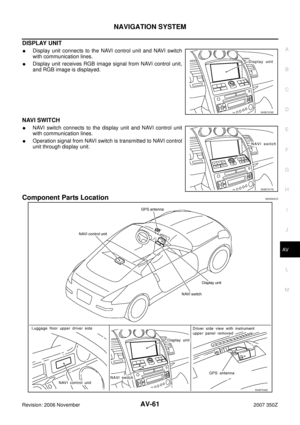 61
61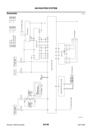 62
62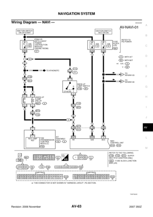 63
63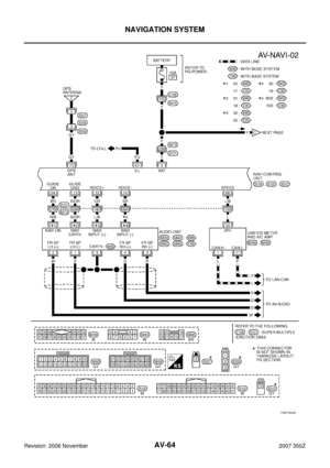 64
64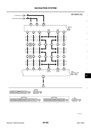 65
65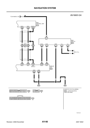 66
66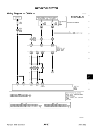 67
67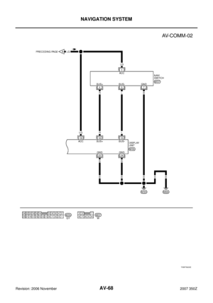 68
68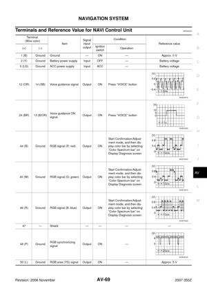 69
69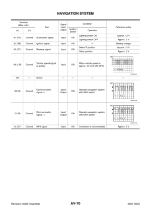 70
70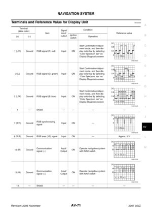 71
71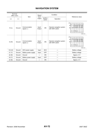 72
72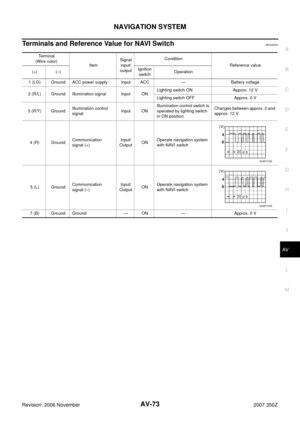 73
73 74
74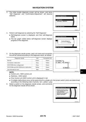 75
75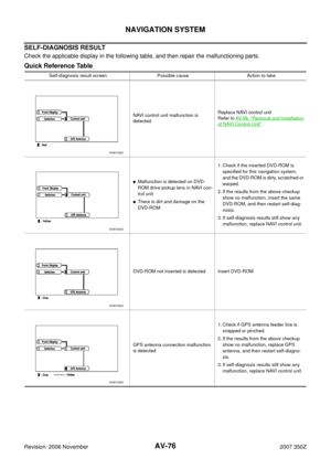 76
76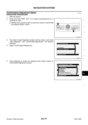 77
77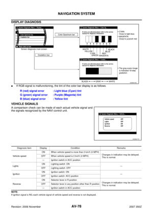 78
78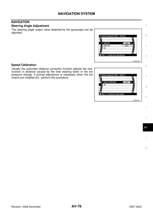 79
79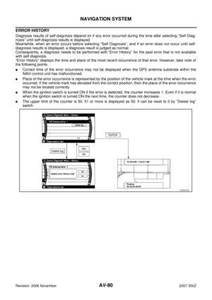 80
80 81
81 82
82 83
83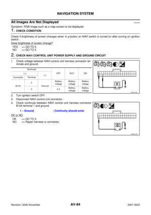 84
84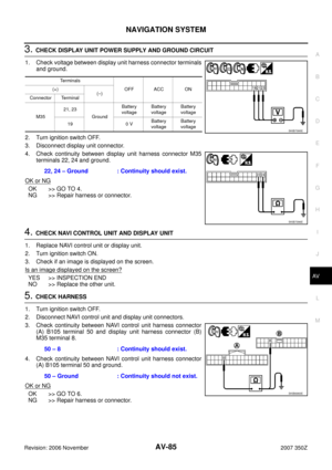 85
85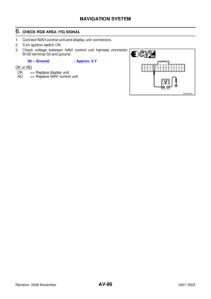 86
86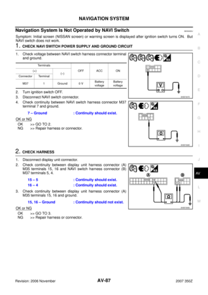 87
87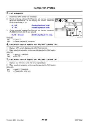 88
88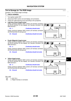 89
89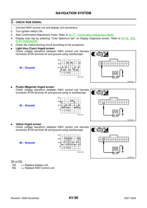 90
90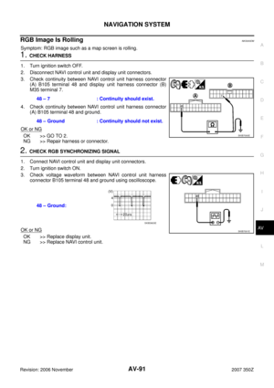 91
91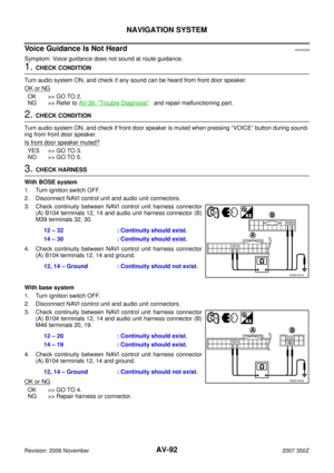 92
92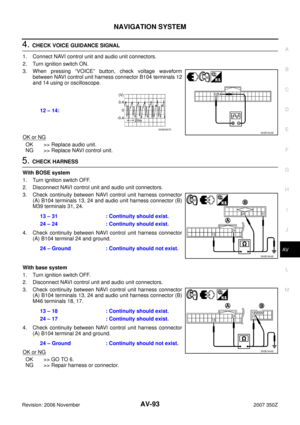 93
93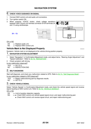 94
94 95
95 96
96 97
97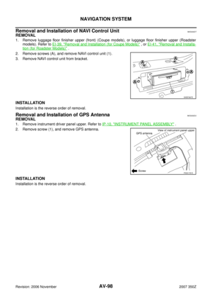 98
98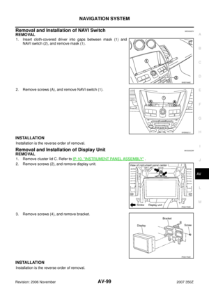 99
99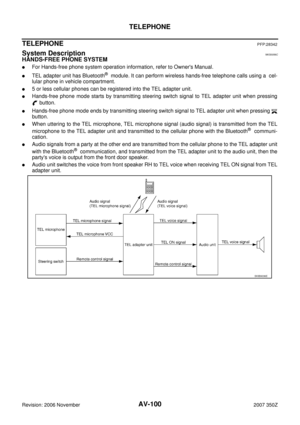 100
100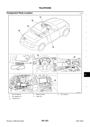 101
101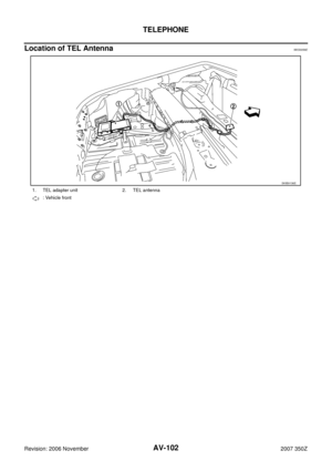 102
102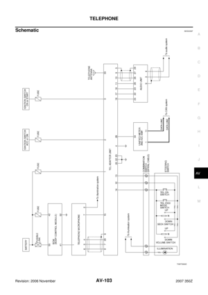 103
103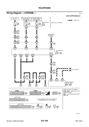 104
104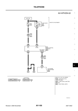 105
105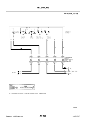 106
106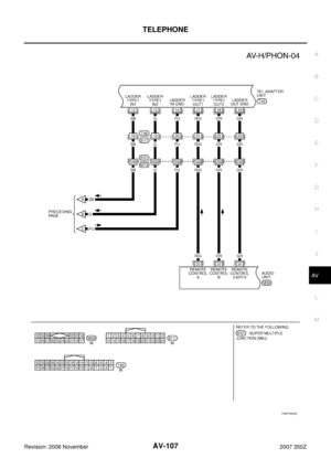 107
107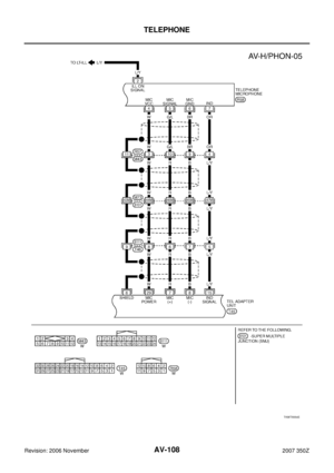 108
108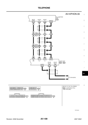 109
109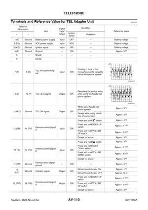 110
110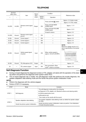 111
111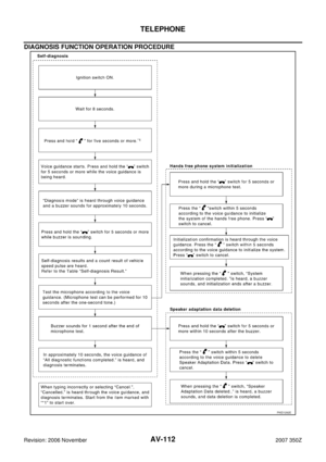 112
112 113
113 114
114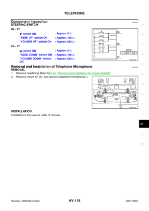 115
115

