2007 MITSUBISHI LANCER EVOLUTION ESP
[x] Cancel search: ESPPage 942 of 1449

FRONT AXLE -Drive Shaft26-14
DISASSEMBLY SERVICE POINTS
AA"T.J. CASE/SPIDER ASSEMBLY REMOVAL
1. Wipe off grease from the spider assembly and the inside
of the T.J. case.
2. Always clean the spider assembly when the grease
contains water or foreign material.
Caution
Do not disassemble the spider assembly.
AB"T.J. BOOT REMOVAL
1. Wipe off grease from the shaft spline.
2. When reusing the T.J. boot, wrap plastic tape around
the shaft spline to avoid damaging the boot.
REASSEMBLY SERVICE POINTS
"AASPIDER ASSEMBLY/T.J. CASE INSTALLATION
1. Apply the specified grease furnished in the repair kit to
the spider assembly between the spider axle and the
roller.
Specified grease: Repair kit grease
Caution
(1) The drive shaft joint uses special grease. Do not
mix old and new or different types of grease.
(2) If the spider assembly has been cleaned, take
special care to apply the specified grease.
2. Install the spider assembly to the shaft from the direction
of the spline bevelled section.
3. After applying the specified grease to the T.J. case, insert
the drive shaft and apply grease one more time.
Specified grease: Repair kit grease
Amount to use: 120±10 g
NOTE
The grease in the repair kit should be divided in half
for use, respectively, at the joint and inside the boot.
Caution
The drive shaft joint uses special grease. Do not mix
old and new or different types of grease.Bevelled
section
Page 979 of 1449

REAR AXLE -Drive Shaft27B-33
DISASSEMBLY SERVICE POINTS
AA"T.J. CASE/SPIDER ASSEMBLY REMOVAL
1. Wipe off grease from the spider assembly and the inside
of the T.J. case.
2. Always clean the spider assembly when the grease
contains water or foreign material.
Caution
Do not disassemble the spider assembly.
AB"T.J. BOOT REMOVAL
1. Wipe off grease from the shaft spline.
2. When reusing the T.J. boot, wrap plastic tape around
the shaft spline to avoid damaging the boot.
REASSEMBLY SERVICE POINTS
"AAT.J. BOOT/SPIDER ASSEMBLY/T.J. CASE
INSTALLATION
1. Apply the specified grease furnished in the repair kit to
the spider assembly between the spider axle and the
roller.
Specified grease: Repair kit grease
Caution
(1) The drive shaft joint uses special grease. Do not
mix old and new or different types of grease.
(2) If the spider assembly has been cleaned, take
special care to apply the specified grease.
2. Install the spider assembly to the shaft from the direction
of the spline bevelled section.
3. After applying the specified grease to the T.J. case, insert
the drive shaft and apply grease one more time.
Specified grease: Repair kit grease
Amount to use: 105±10 g
NOTE
The grease in the repair kit should be divided in half
for use, respectively, at the joint and inside the boot.
Caution
The drive shaft joint uses special grease. Do not mix
old and new or different types of grease.Bevelled
section
Page 1015 of 1449

32-1
POWER PLANT
MOUNT
CONTENTS
GENERAL INFORMATION 2..................
SPECIAL TOOL 3............................
ENGINE MOUNTING 4........................TRANSMISSION MOUNTING 5................
ENGINE ROLL STOPPER, CENTERMEMBER
6 ............................................
CROSSMEMBER* 8..........................
WARNING REGARDING SERVICING OF SUPPLEMENTAL RESTRAINT SYSTEM (SRS) EQUIPPED VEHICLES
WARNING!
(1) Improper service or maintenance of any component of the SRS, or any SRS-related component, can lead to personal
injury or death to service personnel (from inadvertent firing of the air bag) or to driver and passenger (from rendering
the SRS inoperative).
(2) Service or maintenance of any SRS component or SRS-related component must be performed only at an authorized
MITSUBISHI dealer.
(3) MITSUBISHI dealer personnel must thoroughly review this manual, and especially its GROUP 52B - Supplemental
Restraint System (SRS) before beginning any service or maintenance of any component of the SRS or any SRS-related
component.
NOTE
The SRS includes the following components: SRS-ECU, SRS warning lamp, air bag module, clock spring, and interconnecting
wiring. Other SRS-related components (that may have to be removed/installed in connection with SRS service or maintenance) are
indicated in the table of contents by an asterisk (*).
Page 1031 of 1449

FRONT SUSPENSION -On-vehicle Service33A-5
Tightening torque: 52±2 N·m
3. Confirm that the toe-in is at the standard value.
4. Use a turning radius gauge to check that the steering
angle is at the standard value.
Standard value:
Inner wheels31_45’±1_30’
Outer wheels (for reference)27_15’
TOE-OUT ANGLE ON TURNS
To check the steering linkage, especially after the vehicle
has been involved in an accident or if an accident is presumed,
it is advisable to check the toe-out angle on turns in addition
to the wheel alignment.
Conduct this test on the left turn as well as on the right turn.
Standard value:
ItemsSpecifications
Toe-out angle on turns
(inner wheel when outer wheel at 20_)22_00’±1_30’
CAMBER, CASTER AND KINGPIN INCLINATION
Standard value:
ItemsSpecifications
Camber
(Selectable from 2 options)-1_00’±30’* or - 2_00’±30’*
Caster3_55’±30’*
Kingpin inclination13_45’±1_30’
NOTE
1. *: difference between right and left wheels must be less
than 30’
2. Caster and kingpin inclination are preset at the factory
and cannot be adjusted.
SELECTION THE CAMBER
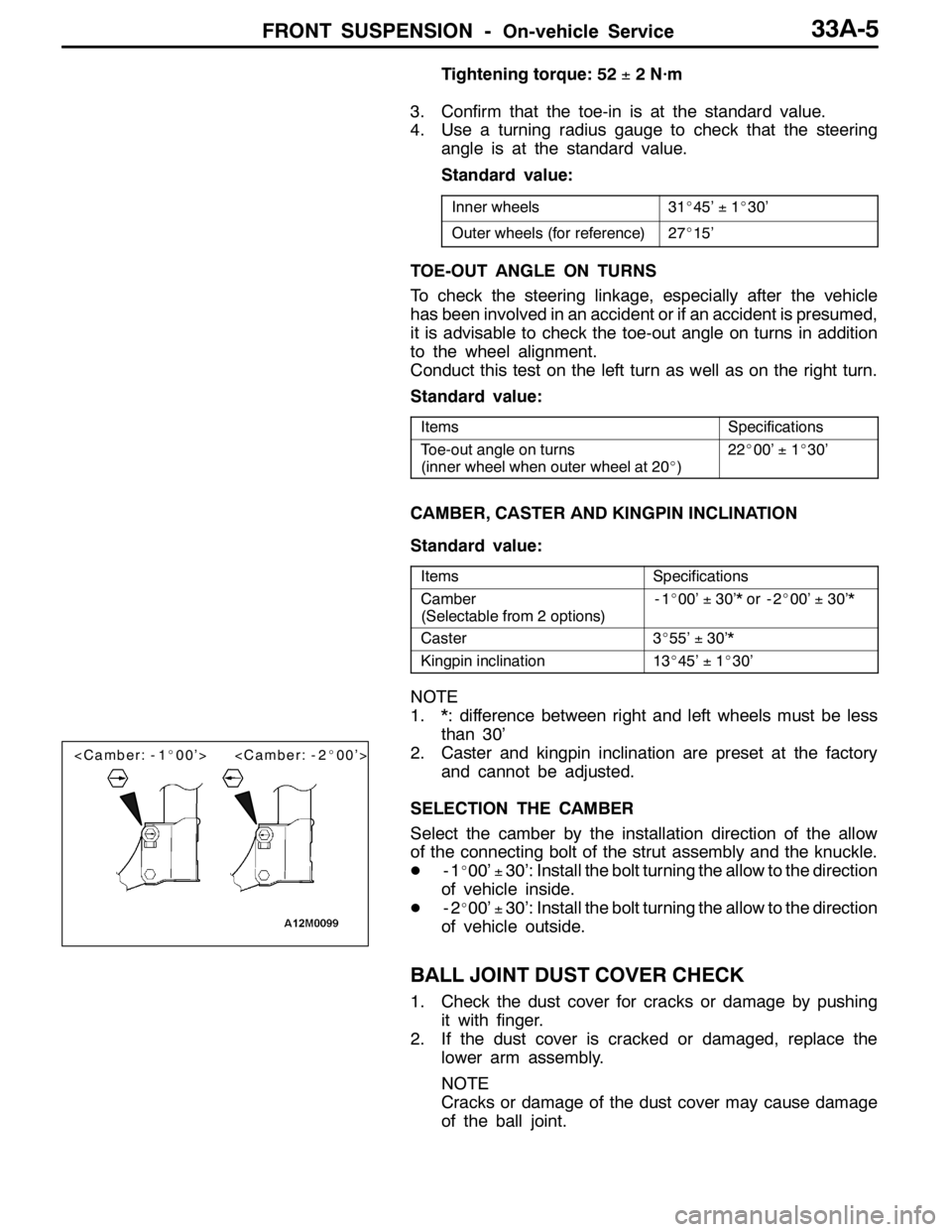
Select the camber by the installation direction of the allow
of the connecting bolt of the strut assembly and the knuckle.
D-1
_00’±30’: Install the bolt turning the allow to the direction
of vehicle inside.
D-2
_00’±30’: Install the bolt turning the allow to the direction
of vehicle outside.
BALL JOINT DUST COVER CHECK
1. Check the dust cover for cracks or damage by pushing
it with finger.
2. If the dust cover is cracked or damaged, replace the
lower arm assembly.
NOTE
Cracks or damage of the dust cover may cause damage
of the ball joint.
Page 1051 of 1449

BASIC BRAKE SYSTEM -On-vehicle Service35A-9
CHECK VALVE OPERATION CHECK
1. Remove the vacuum hose. (Refer to P.35A-17.)
Caution
The check valve should not be disassembled from
the vacuum hose as they are united as one part.
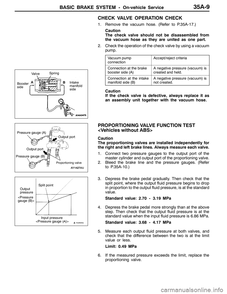
2. Check the operation of the check valve by using a vacuum
pump.
Vacuum pump
connectionAccept/reject criteria
Connection at the brake
booster side (A)A negative pressure (vacuum) is
created and held.
Connection at the intake
manifold side (B)A negative pressure (vacuum) is
not created.
Caution
If the check valve is defective, always replace it as
an assembly unit together with the vacuum hose.
PROPORTIONING VALVE FUNCTION TEST
Caution
The proportioning valves are installed independently for
the right and left brake lines. Always measure each valve.
1. Connect two pressure gauges to the output port of the
master cylinder and output port of the proportioning valve.
2. Bleed the brake line and the pressure gauges. (Refer
to P.35A-10.)
3. Depress the brake pedal gradually. Then check that the
split point, where the output fluid pressure begins to drop
in proportion to the output fluid pressure, is at the standard
value.
Standard value: 2.70 - 3.19 MPa
4. Depress the brake pedal more strongly than at the above
step. Then check that the output fluid pressure is at the
standard value when the input fluid pressure is 6.86 MPa.
Standard value: 3.68 - 4.17 MPa
5. Measure each output fluid pressure at both valves, and
check that the difference between the two is at the limit
value or less.
Limit: 0.49 MPa
6. If the measured pressure exceeds the limit, replace the
proportioning valve.
ValveSpring
Booster
sideA
B
Intake
manifold
side
Pressure gauge (A)
Proportioning valve
Output port
Output port
Pressure gauge (B)
Output
pressureSplit point
Page 1075 of 1449

ABS <4WD> -Troubleshooting35B-5
ABS WARNING LAMP INSPECTION
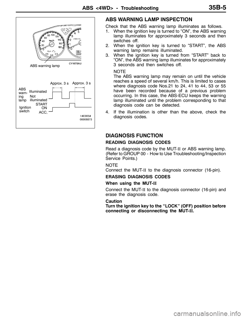
Check that the ABS warning lamp illuminates as follows.
1. When the ignition key is turned to “ON”, the ABS warning
lamp illuminates for approximately 3 seconds and then
switches off.
2. When the ignition key is turned to “START”, the ABS
warning lamp remains illuminated.
3. When the ignition key is turned from “START” back to
“ON”, the ABS warning lamp illuminates for approximately
3 seconds and then switches off.
NOTE
The ABS warning lamp may remain on until the vehicle
reaches a speed of several km/h. This is limited to cases
where diagnosis code Nos.21 to 24, 41 to 44, 53 or 55
have been recorded because of a previous problem
occurring. In this case, the ABS-ECU keeps the warning
lamp illuminated until the problem corresponding to that
diagnosis code can be detected.
4. If the illumination is other than the above, check the
diagnosis codes.
DIAGNOSIS FUNCTION
READING DIAGNOSIS CODES
Read a diagnosis code by the MUT-IIor ABS warning lamp.
(Refer to GROUP 00 - How to Use Troubleshooting/Inspection
Service Points.)
NOTE
Connect the MUT-IIto the diagnosis connector (16-pin).
ERASING DIAGNOSIS CODES
When using the MUT-II
Connect the MUT-IIto the diagnosis connector (16-pin) and
erase the diagnosis code.
Caution
Turn the ignition key to the “LOCK” (OFF) position before
connecting or disconnecting the MUT-II.
Not
illuminated
ABS
warn-
ing
lampIlluminated
Approx. 3 sApprox. 3 s
Ignition
switchSTARTON
ACC,
ABS warning lamp
Page 1077 of 1449

ABS <4WD> -Troubleshooting35B-7
INSPECTION CHART FOR DIAGNOSIS CODES
Diagnosis code No.Inspection itemReference page
11Front right wheel speed sensor (Open circuit or short circuit)35B-9
12Front left wheel speed sensor (Open circuit or short circuit)
13Rear right wheel speed sensor (Open circuit or short circuit)
14Rear left wheel speed sensor (Open circuit or short circuit)
16*ABS-ECU power supply system (Abnormal voltage drop or rise)35B-10
21Front right wheel speed sensor35B-9
22Front left wheel speed sensor
23Rear right wheel speed sensor
24Rear left wheel speed sensor
32Longitudinal G sensor system35B-11
41Front right solenoid valveThe diagnosis codes are output
whenthereisnoresponsetothe
35B-12
42Front left solenoid valve
whenthereis no responsetothe
drive signals for respective solenoid
valvesortheABS ECUpower43Rear right solenoid valvevalves or theABS-ECUpower
supply system is defective.
44Rear left solenoid valve
51Valve relay problem (stays on)35B-30, 31
(Replace the
hydraulic unit and
ABS-ECU.)
52Valve relay problem (stays off) or ABS-ECU power supply system
problem35B-12
53Motor relay problem (stays off) or ABS-ECU power supply system
problem
54Motor relay problem (stays on)35B-30, 31
(Replace the
hydraulic unit and
ABS-ECU.)
55Motor system (seized pump motor) or ABS-ECU power supply system
problem35B-12
63ABS-ECU35B-30, 31
(Replace the
hydraulic unit and
ABS-ECU.)
71Lateral G sensor system35B-13
Page 1115 of 1449

37A-1
STEERING
CONTENTS
GENERAL INFORMATION 2..................
SERVICE SPECIFICATIONS 4.................
LUBRICANTS 4..............................
SEALANT 4..................................
SPECIAL TOOLS 4...........................
ON-VEHICLE SERVICE 7.....................
Steering Wheel Free Play Check 7..............
Steering Angle Check 7........................
Tie Rod End Ball Joint Turning Torque Check 7..
Stationary Steering Effort Check 8...............
Checking Steering Wheel Return to Centre 8.....
Drive Belt Tension Check 8.....................Power Steering Fluid Level Check 9.............
Power Steering Fluid Replacement 9.............
Power Steering System Bleeding 9..............
Oil Pump Pressure Test 10.....................
Power Steering Oil Pressure Switch Check 11....
Ball Joint Dust Cover Check 11.................
STEERING WHEEL* 12.......................
STEERING SHAFT* 14.......................
POWER STEERING GEAR BOX AND
LINKAGE* 16................................
POWER STEERING OIL PUMP 29............
POWER STEERING OIL HOSES 30...........
WARNINGS REGARDING SERVICING OF SUPPLEMENTAL RESTRAINT SYSTEM (SRS) EQUIPPED VEHICLES
WARNING!
(1) Improper service or maintenance of any component of the SRS, or any SRS-related component, can lead to personal
injury or death to service personnel (from inadvertent firing of the air bag) or to the driver and passenger (from rendering
the SRS inoperative).
(2) Service or maintenance of any SRS component or SRS-related component must be performed only at an authorized
MITSUBISHI dealer.
(3) MITSUBISHI dealer personnel must thoroughly review this manual, and especially its GROUP 52B - Supplemental
Restraint System (SRS) before beginning any service or maintenance of any component of the SRS or any SRS-related
component.
NOTE
The SRS includes the following components: SRS-ECU, SRS warning lamp, air bag module, clock spring and interconnecting
wiring. Other SRS-related components (that may have to be removed/installed in connection with SRS service or maintenance) are
indicated in the table of contents by an asterisk (*).