2007 MITSUBISHI LANCER EVOLUTION ESP
[x] Cancel search: ESPPage 1317 of 1449

SRS -AirBagModuleandSeatBeltPre-tensioner
Disposal Procedures52B-73
(6) Disconnect the deployment harnesses as far from
the front passenger’s air bag module as possible and
connect the harnesses to the battery removed from
the vehicle.
Caution
1) Before the deployment, see that no one is near
the front passenger’s air bag module.
2) The deployment makes the inflator of the front
passenger’s air bag very hot. Before handling
the inflator, wait more than 30 minutes for
cooling.
3) If the front passenger’s air bag module fails to
deploy although the procedure is respected,
do not go near the module. Contact your local
distributor.
(7) Discard the deployed air bag module as specified
in Deployed Air Bag Module Disposal Procedures.
(Refer to P.52B-75.)
Seat belt pre-tensioner
(1) Remove the seat belt with pre-tensioner from the
vehicle. (Refer to P.52B-61.)
Caution
Once disconnected, both electrodes of the seat
belt pre-tensioner are short-circuited
automatically to prevent accidental deployment
caused by static etc. Still, in consideration of the
accidental deployment, store the air bag module
on flat place with deployment surface facing up.
Also, do not put anything on it.
(2) Connect deployment harness 6 m or longer with the
SRS air bag adapter harness respectively. Insulate
the connection with tape.
Moreover, the ends of the operation harness should
be connected (short-circuited) to each other. Thus,
it prevents the seat belt pre-tensioner from accidental
deployment caused by static and etc.
Deployment harnesses
SRS air bag
adapter
harness
MR686560Shorted
6 m long
or more Insulation tape
Deployment
harnesses
Page 1318 of 1449

SRS -AirBagModuleandSeatBeltPre-tensioner
Disposal Procedures52B-74
(3) Route a thick wire through the holes in the seat belt
retractor bracket to secure at the top of the wheel
(convex part). (two locations)
(4) Connect the seat belt pre-tensioner connector to the
the SRS air bag adapter harness with the operation
harness attached.
(5) Pull out the seat belt outside the tyre.
Caution
Place the connector of the SRS air bag adapter
harness so that it is not clamped by the tyres at
deployment.
(6) Place an old tyre (without a wheel) on the tyre, which
the seat belt with pre-tensioner is secured on.
(7) Disconnect the deployment harness as far fromthe
seat belt pre-tensioner as possible and connect the
both terminals of the battery removed from the vehicle.
Then deploy.
Caution
1) Before the deployment, see that no one is near
the seat belt pre-tensioner.
2) Before handling the insulator, wait for a while
for cooling.
3) If the seat belt pre-tensioner fails to operate
although the procedure is respected, do not go
near the seat belt pre-tensioner. Contact your
local distributor.
(8) Discard the operated seat belt pre-tensioner
according to Disposal Procedure.(Refer to P.52B-75.)Seat belt pre-tensioner
Deployment harness
Old tyres without
wheels
Deployment harness
Page 1336 of 1449
CHASSIS ELECTRICAL -Combination Meter54A-16
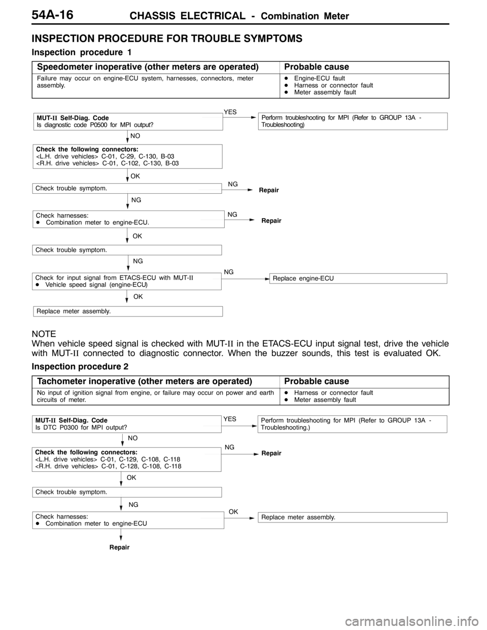
INSPECTION PROCEDURE FOR TROUBLE SYMPTOMS
Inspection procedure 1
Speedometer inoperative (other meters are operated)
Probable cause
Failure may occur on engine-ECU system, harnesses, connectors, meter
assembly.DEngine-ECU fault
DHarness or connector fault
DMeter assembly fault
NO
MUT-IISelf-Diag. Code
Is diagnostic code P0500 for MPI output?YESPerform troubleshooting for MPI (Refer to GROUP 13A -
Troubleshooting)
OK
NG
Check the following connectors:
Repair
OK
Check trouble symptom.
NG
NG
RepairCheck harnesses:
DCombination meter to engine-ECU.
Check trouble symptom.
NG
Replace meter assembly.
OK
Check for input signal from ETACS-ECU with MUT-II
DVehicle speed signal (engine-ECU)NGReplace engine-ECU
NOTE
When vehicle speed signal is checked with MUT-IIin the ETACS-ECU input signal test, drive the vehicle
with MUT-IIconnected to diagnostic connector. When the buzzer sounds, this test is evaluated OK.
Inspection procedure 2
Tachometer inoperative (other meters are operated)
Probable cause
No input of ignition signal from engine, or failure may occur on power and earth
circuits of meter.DHarness or connector fault
DMeter assembly fault
OK
NO
MUT-IISelf-Diag. Code
Is DTC P0300 for MPI output?YESPerform troubleshooting for MPI (Refer to GROUP 13A -
Troubleshooting.)
NG
NG
RepairRepair
Check trouble symptom.
OK
Check the following connectors:
Replace meter assembly.Check harnesses:
DCombination meter to engine-ECU
Page 1371 of 1449

SWS -Troubleshooting54B-7
TROUBLE SYMPTOM CHART
Trouble symptomInspection
procedureReference
page
No communication with MUT-IIA-154B-10
BuzzersLights left ON reminder warning function not working normally.B-154B-10
Central lockingCentral door locking system not working at all.C-154B-11g
Some doors not locking or unlocking.C-254B-11
Power windowPower windows not working at all.D-154B-12
Power windows are not operated with the power window main
switch.
Driver’s power window not responding to power window main
switch.D-254B-13
Windows not responding to passenger or rear power window
switches.D-354B-14
Passenger or rear power windows not responding to power window
main switch.D-454B-15
Power window timer function not working normally.D-554B-15
While the window is winding up, it suddenly starts coming down
again.D-654B-16
Safety mechanism (to prevent jamming of fingers, etc.) not
working.D-754B-16
Windshield wipers
dh
The windshield wipers do not work at all.E-154B-17p
and washerThe windshield wipers only operate at LO speed (though the wipers
and washer can be switched OFF).E-254B-17
The windshield wipers do not respond to any switch position.E-354B-18
The windshield wipers do not stop in the normal predetermined
position.E-454B-18
The windshield washer does not work at all.E-554B-19
Windshield wipers are not operated with the switch in INT,
WASHER and MIST positions, and operated in a low mode with the
switch in Lo and Hi positions.E-654B-19
Headlamps, tail lampsExcept for lighting switch“OFF,” the headlamps only respond to the
“low-beam” position.
F-154B-20
The tail lamps do not work.F-254B-20
The headlamps (low-beam) do not light.F-354B-21
The headlamps (high-beam) do not light.F-454B-21
The headlamps (low or high-beam) do not work when the passing
switch is ON.F-554B-22
The headlamp automatic cut-off function is not working normally.F-654B-22
Rear fog lampRear fog lamp is not properly illuminated.G-154B-23
Flasher timerThe turn signal lamps do not light.H-154B-24
The hazard warning lamps do not light up.H-254B-24
Room lampsThe room lamps do not come ON or OFF normally.I-154B-25
Page 1375 of 1449
SWS -Troubleshooting54B-11
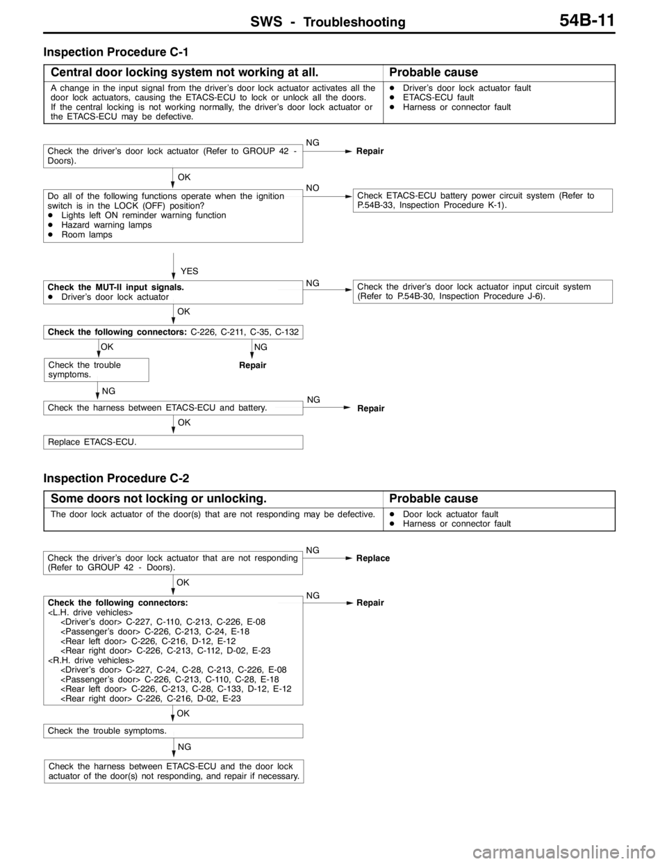
Inspection Procedure C-1
Central door locking system not working at all.
Probable cause
A change in the input signal from the driver’s door lock actuator activates all the
door lock actuators, causing the ETACS-ECU to lock or unlock all the doors.
If the central locking is not working normally, the driver’s door lock actuator or
the ETACS-ECU may be defective.DDriver’s door lock actuator fault
DETACS-ECU fault
DHarness or connector fault
NG
Repair
OK
Replace ETACS-ECU.
NG
Check the harness between ETACS-ECU and battery.NG
Repair
OK
Check the trouble
symptoms.
OK
Check the following connectors:C-226, C-211, C-35, C-132
YES
Check the driver’s door lock actuator (Refer to GROUP 42 -
Doors).NG
Repair
Do all of the following functions operate when the ignition
switch is in the LOCK (OFF) position?
DLights left ON reminder warning function
DHazard warning lamps
DRoom lampsNOCheck ETACS-ECU battery power circuit system (Refer to
P.54B-33, Inspection Procedure K-1). OK
Check the MUT-II input signals.
DDriver’s door lock actuatorNGCheck the driver’s door lock actuator input circuit system
(Refer to P.54B-30, Inspection Procedure J-6).
Inspection Procedure C-2
Some doors not locking or unlocking.
Probable cause
The door lock actuator of the door(s) that are not responding may be defective.DDoor lock actuator fault
DHarness or connector fault
NG
Check the harness between ETACS-ECU and the door lock
actuator of the door(s) not responding, and repair if necessary.
OK
Check the trouble symptoms.
OK
Check the following connectors:
Repair
Check the driver’s door lock actuator that are not responding
(Refer to GROUP 42 - Doors).NG
Replace
Page 1377 of 1449
SWS -Troubleshooting54B-13
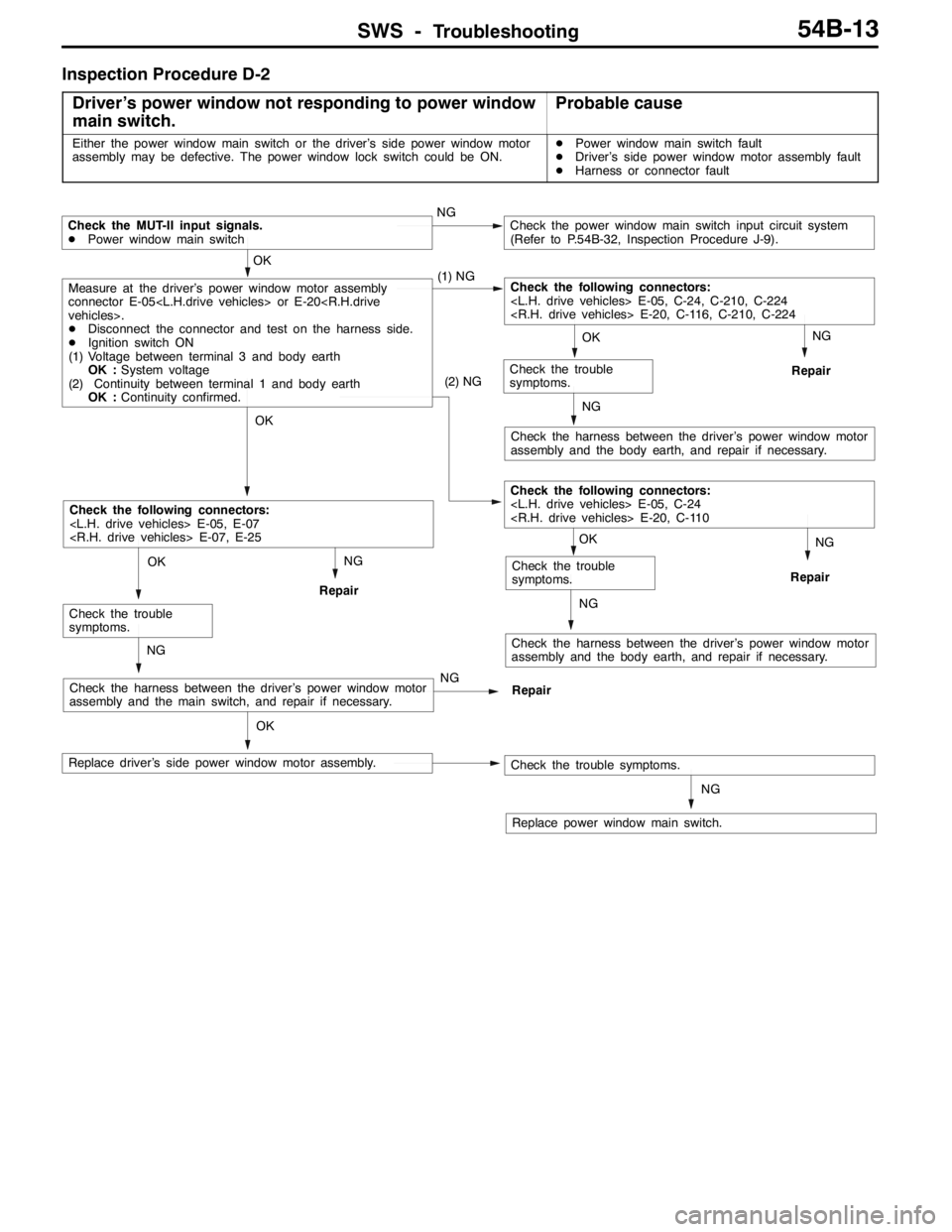
Inspection Procedure D-2
Driver’s power window not responding to power window
main switch.
Probable cause
Either the power window main switch or the driver’s side power window motor
assembly may be defective. The power window lock switch could be ON.DPower window main switch fault
DDriver’s side power window motor assembly fault
DHarness or connector fault
NG
Replace power window main switch.
OK
Replace driver’s side power window motor assembly.
NG
Check the harness between the driver’s power window motor
assembly and the body earth, and repair if necessary.
NG
Repair
OK
Check the trouble
symptoms.
(2) NG
Check the following connectors:
NG
Repair
NG
Check the harness between the driver’s power window motor
assembly and the body earth, and repair if necessary.
NG
Repair
OK
Check the trouble
symptoms.
NG
Check the harness between the driver’s power window motor
assembly and the main switch, and repair if necessary.NG
Repair
OK
Check the trouble
symptoms.
OK
Check the following connectors:
OK
Measure at the driver’s power window motor assembly
connector E-05
DDisconnect the connector and test on the harness side.
DIgnition switch ON
(1) Voltage between terminal 3 and body earth
OK :System voltage
(2) Continuity between terminal 1 and body earth
OK :Continuity confirmed.(1) NGCheck the following connectors:
Check the MUT-II input signals.
DPower window main switchNGCheck the power window main switch input circuit system
(Refer to P.54B-32, Inspection Procedure J-9).
Check the trouble symptoms.
Page 1378 of 1449
SWS -Troubleshooting54B-14
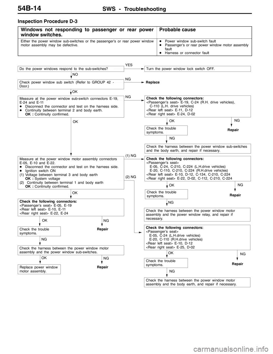
Inspection Procedure D-3
Windows not responding to passenger or rear power
window switches.
Probable cause
Either the power window sub-switches or the passenger’s or rear power window
motor assembly may be defective.DPower window sub-switch fault
DPassenger’s or rear power window motor assembly
fault
DHarness or connector fault
NG
Repair
NG
Check the harness between the power window sub-switches
and the body earth, and repair if necessary.
NG
Repair
NG
Check the harness between the power window motor
assembly and the power window relay, and repair if
necessary.NG
Repair
NG
Check the harness between the power window motor
assembly and the body earth, and repair if necessary.
NG
Repair
OK
Replace power window
motor assembly.
NG
Repair
NG
Check the harness between the power window motor
assembly and the power window sub-switches.
OK
Check the trouble
symptoms.
OK
Check the trouble
symptoms.
(2) NG
Check the following connectors:
E-05, C-24 (L.H.drive vehicles)
E-20, C-110 (R.H.drive vehicles)
OK
Check the trouble
symptoms.
OK
Check the trouble
symptoms.
OK
Check the following connectors:
OK
Measure at the power window motor assembly connectors
E-05, E-10 and E-22.
DDisconnect the connector and test on the harness side.
DIgnition switch ON
(1) Voltage between terminal 3 and body earth
OK :System voltage
(2) Continuity between terminal 1 and body earth
OK :Continuity confirmed.(1) NGCheck the following connectors:
E-05, C-24, C-210, C-224 (L.H.drive vehicles)
E-20, C-110, C-210, C-224 (R.H.drive vehicles)
OK
Measure at the power window sub-switch connectors E-19,
E-24 and E-11
DDisconnect the connector and test on the harness side.
DContinuity between terminal 2 and body earth.
OK :Continuity confirmed.NGCheck the following connectors:
C-110 (L.H. drive vehicles)
Check power window sub switch (Refer to GROUP 42 -
Door.)NG
Replace
YESTurn the power window lock switch OFF.
NO
Do the power windows respond to the sub-switches?
Page 1379 of 1449
SWS -Troubleshooting54B-15
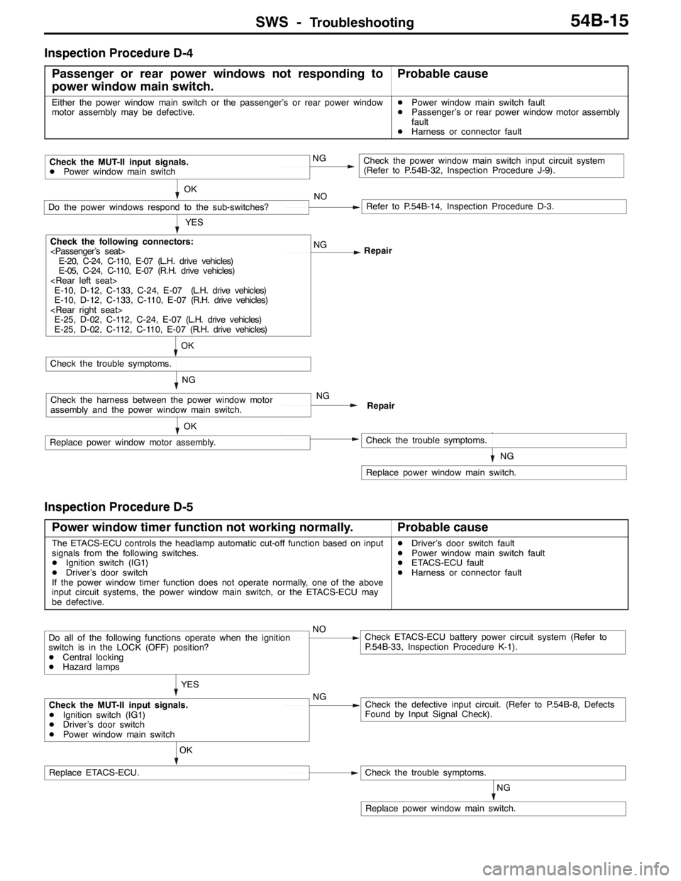
Inspection Procedure D-4
Passenger or rear power windows not responding to
power window main switch.
Probable cause
Either the power window main switch or the passenger’s or rear power window
motor assembly may be defective.DPower window main switch fault
DPassenger’s or rear power window motor assembly
fault
DHarness or connector fault
NG
Replace power window main switch.
OK
Replace power window motor assembly.Check the trouble symptoms.
NGCheck the harness between the power window motor
assembly and the power window main switch.NG
Repair
OK
Check the trouble symptoms.
YES
Check the following connectors:
E-20, C-24, C-110, E-07 (L.H. drive vehicles)
E-05, C-24, C-110, E-07 (R.H. drive vehicles)
E-10, D-12, C-133, C-24, E-07 (L.H. drive vehicles)
E-10, D-12, C-133, C-110, E-07 (R.H. drive vehicles)
E-25, D-02, C-112, C-24, E-07 (L.H. drive vehicles)
E-25, D-02, C-112, C-110, E-07 (R.H. drive vehicles)NG
Repair
OK
Do the power windows respond to the sub-switches?NORefer to P.54B-14, Inspection Procedure D-3.
Check the MUT-II input signals.
DPower window main switchNGCheck the power window main switch input circuit system
(Refer to P.54B-32, Inspection Procedure J-9).
Inspection Procedure D-5
Power window timer function not working normally.
Probable cause
The ETACS-ECU controls the headlamp automatic cut-off function based on input
signals from the following switches.
DIgnition switch (IG1)
DDriver’s door switch
If the power window timer function does not operate normally, one of the above
input circuit systems, the power window main switch, or the ETACS-ECU may
be defective.DDriver’s door switch fault
DPower window main switch fault
DETACS-ECU fault
DHarness or connector fault
NG
Replace power window main switch.
OK
Replace ETACS-ECU.Check the trouble symptoms.
Check the MUT-II input signals.
DIgnition switch (IG1)
DDriver’s door switch
DPower window main switchNGCheck the defective input circuit. (Refer to P.54B-8, Defects
Found by Input Signal Check).
Do all of the following functions operate when the ignition
switch is in the LOCK (OFF) position?
DCentral locking
DHazard lampsNOCheck ETACS-ECU battery power circuit system (Refer to
P.54B-33, Inspection Procedure K-1).
YES