2007 MITSUBISHI LANCER EVOLUTION ESP
[x] Cancel search: ESPPage 772 of 1449
ENGINE AND EMISSION CONTROL -Engine Control System17-2
ENGINE CONTROL SYSTEM
GENERAL INFORMATION
A cable-type accelerator mechanism and a
suspended-type pedal have been adopted.
SERVICE SPECIFICATIONS
ItemsStandard value
Accelerator cable play mm1-2
Engineidlespeedr/min850±50Engineidle speed±/min850±50
ON-VEHICLE SERVICE
ACCELERATOR CABLE CHECK AND
ADJUSTMENT
1. Turn A/C and lamps OFF.
Inspect and adjust at no load.
2. Warm engine until stabilized at idle.
3. Confirm idle speed is at prescribed value.
Standard value: 850±50 r/min
4. Stop engine (ignition switch OFF).
5. Confirm there are no sharp bends in accelerator cable.
6. Check inner cable for correct slack.
Standard value: 1 - 2 mm
7. If there is too much slack or no slack, adjust play by
the following procedures.
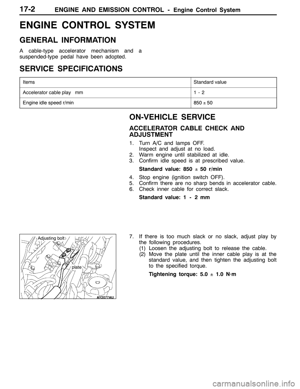
(1) Loosen the adjusting bolt to release the cable.
(2) Move the plate until the inner cable play is at the
standard value, and then tighten the adjusting bolt
to the specified torque.
Tightening torque: 5.0±1.0 N·m
plate
Adjusting bolt
Page 774 of 1449

ENGINE AND EMISSION CONTROL -Emission Control System17-4
EMISSION CONTROL SYSTEM
GENERAL INFORMATION
The emission control system consists of the following subsystems:
DCrankcase emission control system
DEvaporative emission control system
DExhaust emission control system
ItemsNameSpecification
Crankcase emission
control systemPositive crankcase ventilation (PCV) valveVariable flow type
(Purpose: HC reduction)
Evaporative emission
control systemCanister
Purge control solenoid valve
Check valveEquipped
Duty cycle type solenoid valve
Equipped
(Purpose: HC reduction)
Exhaust emission
control systemAir-fuel ratio control device - MPI systemOxygen sensor feedback type
(Purpose: CO, HC, NOx reduction)
Exhaust gas recirculation system
DEGR valve
DEGR control solenoid valveEquipped
Single type
Duty cycle type solenoid valve
(Purpose: NOx reduction)
Catalytic converterMonolith type
(Purpose: CO, HC, NOx reduction)
EMISSION CONTROL DEVICE REFERENCE TABLE
Related partsCrankcase
emission
control
systemEvaporative
emission
control
systemAir/fuel
ratio
control
systemCatalytic
converterExhaust
gas
recirculation
systemReference
page
PCV valve×17-9
Purge control solenoid valve×17-12
Check valve×17-12
MPI system component××GROUP 13A
Catalytic converter×17-19
EGR valve×17-15
EGR control solenoid valve×17-16
Page 810 of 1449

22A-2
MANUAL
TRANSMISSION
CONTENTS
GENERAL 3.................................
Outline of Changes 3...........................
GENERAL INFORMATION 3..................
SERVICE SPECIFICATION 3..................
LUBRICANTS 3..............................
SPECIAL TOOLS 4...........................
TROUBLESHOOTING
ON-VEHICLE SERVICE 40....................
Transmission Oil Check 40......................
Transmission Oil Replacement 40................
Transfer Oil Check 40..........................
Transfer Oil Replacement 40....................
Fluid Check
Bleeding
Hydraulic Pressure Check
Wheel Speed Sensor Output Voltage
Measurement
TRANSMISSION CONTROL* 46...............
TRANSFER ASSEMBLY 49...................
TRANSMISSION ASSEMBLY 52...............
4WD-ECU
SENSOR, SWITCH AND RELAY
AYC> 56.....................................
HYDRAULIC UNIT Refer to GROUP27B.......
WARNING REGARDING SERVICING OF SUPPLEMENTAL RESTRAINT SYSTEM (SRS) EQUIPPED VEHICLES
WARNING!
(1) Improper service or maintenance of any component of the SRS, or any SRS-related component, can lead to personal
injury or death to service personnel (from inadvertent firing of the air bag) or to driver and passenger (from rendering
the SRS inoperative).
(2) Service or maintenance of any SRS component or SRS-related component must be performed only at an authorized
MITSUBISHI dealer.
(3) MITSUBISHI dealer personnel must thoroughly review this manual, and especially its GROUP 52B - Supplemental
Restraint System (SRS) before beginning any service or maintenance of any component of the SRS or any SRS-related
component.
NOTE
The SRS includes the following components: SRS-ECU, SRS warning lamp, air bag module, clock spring, and interconnecting
wiring. Other SRS-related components (that may have to be removed/installed in connection with SRS service or maintenance) are
indicated in the table of contents by an asterisk (*).
Page 816 of 1449
MANUAL TRANSMISSION - Troubleshooting
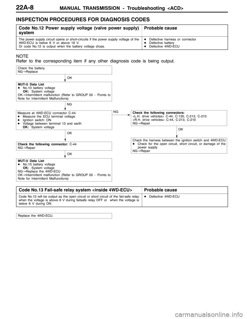
INSPECTION PROCEDURES FOR DIAGNOSIS CODES
Code No.12 Power supply voltage (valve power supply)
systemProbable cause
The power supply circuit opens or short-circuits if the power supply voltage of the
4WD-ECU is below 9 V or above 18 V.
Or code No.12 is output when the battery voltage drops.DDefective harness or connector
DDefective battery
DDefective 4WD-ECU
NOTE
Refer to the corresponding item if any other diagnosis code is being output.
OKOK
NG
NG
OK
Check the battery.
NG→Replace
Measure at 4WD-ECU connector C-44.
DMeasure the ECU terminal voltage.
DIgnition switch: ON
DVoltage between terminal 13 and earth
OK:System voltageCheck the following connectors:
NG→Repair
MUT-IIData List
DNo.10 battery voltage
OK:System voltage
OK→Intermittent malfunction (Refer to GROUP 00 - Points to
Note for Intermittent Malfunctions)
OK
Check the following connector:C-44
NG→Repair
MUT-IIData List
DNo.10 battery voltage
OK:System voltage
NG→Replace the 4WD-ECU
OK→Intermittent malfunction (Refer to GROUP 00 - Points to
Note for Intermittent Malfunctions)
Check the harness between the ignition switch and 4WD-ECU
DCheck for the open circuit, short circuit, or damage of the
power supply
NG→Repair
Code No.13 Fail-safe relay system
Code No.13 will be output as the open circuit or short circuit of the fail-safe relay
when the voltage is above 6 V during failsafe relay OFF or when the voltage is
below 6 V during ON.DDefective 4WD-ECU
Replace the 4WD-ECU.
Page 817 of 1449
MANUAL TRANSMISSION - Troubleshooting
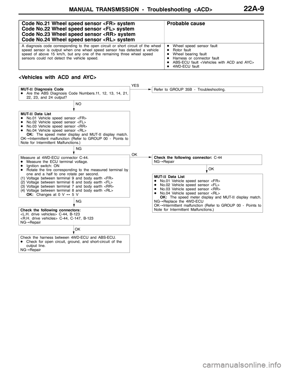
Code No.21 Wheel speed sensor
Code No.22 Wheel speed sensor
Code No.23 Wheel speed sensor
Code No.24 Wheel speed sensor
A diagnosis code corresponding to the open circuit or short circuit of the wheel
speed sensor is output when one wheel speed sensor has detected a vehicle
speed of above 15 km/h, but any one of the remaining three wheel speed
sensors could not detect the vehicle speed.DWheel speed sensor fault
DRotor fault
DWheel bearing fault
DHarness or connector fault
DABS-ECU fault
D4WD-ECU fault
OKNGYES
NO
OK
Measure at 4WD-ECU connector C-44.
DMeasure the ECU terminal voltage.
DIgnition switch: ON
DRotate the tire corresponding to the measured terminal by
one and a half to one rotate per second.
(1) Voltage between terminal 9 and body earth
(2) Voltage between terminal 6 and body earth
(3) Voltage between terminal 7 and body earth
(4) Voltage between terminal 8 and body earth
OK:Changes at 0 V↔5VCheck the following connector:C-44
NG→Repair
Check the following connectors:
NG→Repair
MUT-IIDiagnosis Code
DAre the ABS Diagnosis Code Numbers.11, 12, 13, 14, 21,
22, 23, and 24 output?Refer to GROUP 35B - Troubleshooting.
NG
MUT-IIData List
DNo.01 Vehicle speed sensor
DNo.02 Vehicle speed sensor
DNo.03 Vehicle speed sensor
DNo.04 Vehicle speed sensor
OK:The speed meter display and MUT-IIdisplay match.
OK→Intermittent malfunction (Refer to GROUP 00 - Points to
Note for Intermittent Malfunctions.)
OK
Check the harness between 4WD-ECU and ABS-ECU.
DCheck for open circuit, ground, and short-circuit of the
output line.
NG→Repair
MUT-IIData List
DNo.01 Vehicle speed sensor
DNo.02 Vehicle speed sensor
DNo.03 Vehicle speed sensor
DNo.04 Vehicle speed sensor
OK:The speed meter display and MUT-IIdisplay match.
NG→Replace the 4WD-ECU
OK→Intermittent malfunction (Refer to GROUP 00 - Points to
Note for Intermittent Malfunctions.)
Page 819 of 1449
MANUAL TRANSMISSION - Troubleshooting
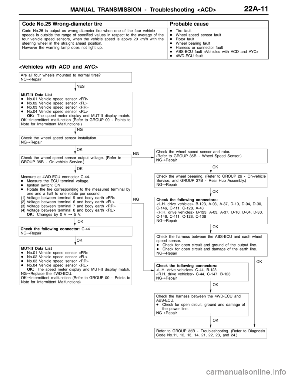
Code No.25 Wrong-diameter tireProbable cause
Code No.25 is output as wrong-diameter tire when one of the four vehicle
speeds is outside the range of specified values in respect to the average of the
four vehicle speed sensors, when the vehicle speed is above 20 km/h with the
steering wheel in the straight ahead position.
However the warning lamp does not light up.DTire fault
DWheel speed sensor fault
DRotor fault
DWheel bearing fault
DHarness or connector fault
DABS-ECU fault
D4WD-ECU fault
OK NG
OK
Check the following connector:C-44
NG→Repair
Check the following connectors:
NG→Repair OKYES
OK
OK
Check the wheel speed sensor and rotor.
(Refer to GROUP 35B - Wheel Speed Sensor.)
NG→Repair
Check the wheel speed sensor output voltage. (Refer to
GROUP 35B - On-vehicle Service.)OK
Check the wheel speed sensor installation.
NG→Repair
NG
OK
Check the wheel beearing. (Refer to GROUP 26 - On-vehicle
Service, and GROUP 27B - Rear Hub Assembly.)
NG→Repair
OK
Check the following connectors:
C-146, C-111, C-128, A-43
C-146, C-111, C-128, C-136
NG→Repair NG
MUT-IIData List
DNo.01 Vehicle speed sensor
DNo.02 Vehicle speed sensor
DNo.03 Vehicle speed sensor
DNo.04 Vehicle speed sensor
OK:The speed meter display and MUT-IIdisplay match.
OK→Intermittent malfunction (Refer to GROUP 00 - Points to
Note for Intermittent Malfunctions.)
Measure at 4WD-ECU connector C-44.
DMeasure the ECU terminal voltage.
DIgnition switch: ON
DRotate the tire corresponding to the measured terminal by
one and a half to one rotate per second.
(1) Voltage between terminal 9 and body earth
(2) Voltage between terminal 6 and body earth
(3) Voltage between terminal 7 and body earth
(4) Voltage between terminal 8 and body earth
OK:Changes by 0 V↔5V.
MUT-IIData List
DNo.01 Vehicle speed sensor
DNo.02 Vehicle speed sensor
DNo.03 Vehicle speed sensor
DNo.04 Vehicle speed sensor
OK:The speed meter display and MUT-IIdisplay match.
NG→Replace the 4WD-ECU.
OK→Intermittent malfunction (Refer to GROUP 00 - Points to
Note for Intermittent Malfunctions)
Refer to GROUP 35B - Troubleshooting. (Refer to Diagnosis
Code No.11, 12, 13, 14, 21, 22, 23, and 24.)
Are all four wheels mounted to normal tires?
NO→Repair
Check the harness between the ABS-ECU and each wheel
speed sensor.
DCheck for open circuit and ground of the output line.
DCheck for open circuit and damage of the earth line.
NG→Repair
OK
Check the harness between the 4WD-ECU and
ABS-ECU.
DCheck for open circuit, ground and damage of
the power line.
NG→RepairOK
Page 821 of 1449
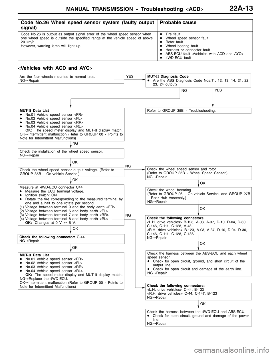
MANUAL TRANSMISSION - Troubleshooting
Code No.26 Wheel speed sensor system (faulty output
signal)Probable cause
Code No.26 is output as output signal error of the wheel speed sensor when
one wheel speed is outside the specified range at the vehicle speed of above
20 km/h.
However, warning lamp will light up.DTire fault
DWheel speed sensor fault
DRotor fault
DWheel bearing fault
DHarness or connector fault
DABS-ECU fault
D4WD-ECU fault
OK NG
OK
Check the following connector:C-44
NG→Repair
Check the following connectors:
NG→Repair OK
Check the harness between the 4WD-ECU and ABS-ECU.
DCheck for open circuit, ground and damage of the power
line.
NG→RepairYES
OK OK
Check the wheel speed sensor and rotor.
(Refer to GROUP 35B - Wheel Speed Sensor.)
NG→RepairCheck the wheel speed sensor output voltage. (Refer to
GROUP 35B - On-vehicle Service.)OK
Check the installation of the wheel speed sensor.
NG→Repair
NG
OK
Check the wheel beearing.
(Refer to GROUP 26 - On-vehicle Service, and GROUP 27B
- Rear Hub Assembly.)
NG→Repair
OK
Check the following connectors:
C-146, C-111, C-128, A-43
C-146, C-111, C-128, C-136
NG→Repair NG
MUT-IIData List
DNo.01 Vehicle speed sensor
DNo.02 Vehicle speed sensor
DNo.03 Vehicle speed sensor
DNo.04 Vehicle speed sensor
OK:The speed meter display and MUT-IIdisplay match.
OK→Intermittent malfunction (Refer to GROUP 00 - Points to
Note for Intermittent Malfunctions)
Measure at 4WD-ECU connector C44.
DMeasure the ECU terminal voltage.
DIgnition switch: ON
DRotate the tire corresponding to the measured terminal by
one and a half to one rotate per second.
(1) Voltage between terminal 9 and the body earth
(2) Voltage between terminal 6 and body earth
(3) Voltage between terminal 7 and body earth
(4) Voltage between terminal 8 and body earth
OK:Changes at 0 V↔5V.
MUT-IIData List
DNo.01 Vehicle speed sensor
DNo.02 Vehicle speed sensor
DNo.03 Vehicle speed sensor
DNo.04 Vehicle speed sensor
OK:The speed meter display and MUT-IIdisplay match.
NG→Replace the 4WD-ECU.
OK→Intermittent malfunction (Refer to GROUP 00 - Points to
Note for Intermittent Malfunctions)Check the harness between the ABS-ECU and each wheel
speed sensor.
DCheck for open circuit, ground, and short circuit of the
output line.
DCheck for open circuit and damage of the earth line.
NG→Repair YES
NO
Refer to GROUP 35B - Troubleshooting.
Are the four wheels mounted to normal tires.
NO→RepairMUT-IIDiagnosis Code
DAre the ABS Diagnosis Code Nos.11, 12, 13, 14, 21, 22,
23, 24 output?
Page 845 of 1449

MANUAL TRANSMISSION - Troubleshooting
ACTUATOR TEST JUDGEMENT VALUE
Item
no.Check itemTest descriptionNormal state
01Bleeding
according to the steering angle, and operate
the Proportional valve for five minutes.Make sure no air leaks from the bleeder
screw on the transfer.
02Bleeding
according to the steering angle, and operate
the directional valve for five minutes.Make sure no air leaks from the bleeder
screw on the torque transfer differential.
03Check the oil vol-
umeOperate the directional valve to the left and
right for 20 seconds.Check that the oil volume of the reservoir
tank is appropriate.
04Electric pump
driveOperate the electric pump for 5 seconds.Operation sounds of the electric pump
can be heard.
05Check the opera-
tions of the ACDOperate the Proportional valve
supply the maximum oil pressure to the multi
plate clutch.9Generate the tight corner braking
phenomenon.
06Check clutch op-
erations
maximum oil pressure to the left clutch.When the wheels are lifted, speed
difference will occur between the rear
left and right wheels.
07Check clutch op-
erations
maximum oil pressure to the right clutch.When the wheels are lifted, speed
difference will occur between the rear
left and right wheels.
08Control OFFTurn OFF the electric pump relay, and turn
OFF the control of the ACD and AYC.In actual driving, there is difference
between control ON and OFF.
(1) The actuator test can be executed only when all the following conditions are satisfied.
DAll wheel speed sensor inputs below 20 km/h
DNo system malfunction detected
DSteering angle is within±30 degrees from the neutral position
(2) When the actuator test corresponds to one of the following conditions, forced driving will be cleared.
DWhen any one of the wheel speed sensor input is detected to be above 20 km/h (excluding
Item No.08 “Control OFF”.)
DWhen system malfunction is detected (excluding diagnostic code No.82, 84, and 85)
DWhen the forced drive time is exceeded
DWhen the MUT-IIis removed
DWhen the Clear key of the MUT-IIis operated