2007 MITSUBISHI LANCER EVOLUTION ESP
[x] Cancel search: ESPPage 1381 of 1449

SWS -Troubleshooting54B-17
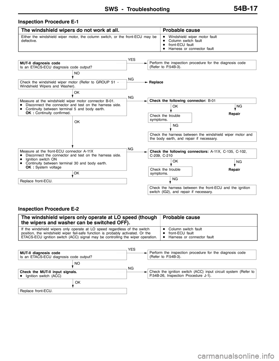
Inspection Procedure E-1
The windshield wipers do not work at all.
Probable cause
Either the windshield wiper motor, the column switch, or the front-ECU may be
defective.DWindshield wiper motor fault
DColumn switch fault
Dfront-ECU fault
DHarness or connector fault
OK
Replace front-ECU.
NO
NG
Replace
MUT-II diagnosis code
Is an ETACS-ECU diagnosis code output?YESPerform the inspection procedure for the diagnosis code
(Refer to P.54B-3).
NG
Repair
NG
Check the harness between the windshield wiper motor and
the body earth, and repair if necessary.
OK
Check the trouble
symptoms.
NG
Repair
NG
Check the harness between the front-ECU and the ignition
switch (IG2), and repair if necessary.
OK
Check the trouble
symptoms.
OK
Measure at the front-ECU connector A-11X
DDisconnect the connector and test on the harness side.
DIgnition switch ON
DContinuity between terminal 30 and body earth.
OK :System voltageNGCheck the following connectors:A-11X, C-135, C-102,
C-209, C-210
OK
Measure at the windshield wiper motor connector B-01.
DDisconnect the connector and test on the harness side.
DContinuity between terminal 5 and body earth.
OK :Continuity confirmed.NGCheck the following connector:B-01
Check the windshield wiper motor (Refer to GROUP 51 -
Windshield Wipers and Washer).
Inspection Procedure E-2
The windshield wipers only operate at LO speed (though
the wipers and washer can be switched OFF).
Probable cause
If the windshield wipers only operate at LO speed regardless of the switch
position, the windshield wiper fail-safe function is probably activated. Or the
ETACS-ECU ignition switch (ACC) signal may be controlling the wiper operation.DColumn switch fault
Dfront-ECU fault
DHarness or connector fault
OK
Replace front-ECU.
MUT-II diagnosis code
Is an ETACS-ECU diagnosis code output?YESPerform the inspection procedure for the diagnosis code
(Refer to P.54B-3).
Check the MUT-II input signals.
DIgnition switch (ACC)NGCheck the ignition switch (ACC) input circuit system (Refer to
P.54B-26, Inspection Procedure J-1). NO
Page 1382 of 1449

SWS -Troubleshooting54B-18
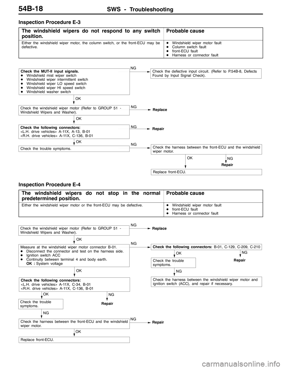
Inspection Procedure E-3
The windshield wipers do not respond to any switch
position.
Probable cause
Either the windshield wiper motor, the column switch, or the front-ECU may be
defective.DWindshield wiper motor fault
DColumn switch fault
Dfront-ECU fault
DHarness or connector fault
OK
Replace front-ECU.
NG
Check the harness between the front-ECU and the windshield
wiper motor. NG
Repair
OK
Check the trouble symptoms.
OK
Check the following connectors:
Repair
OK
Check the windshield wiper motor (Refer to GROUP 51 -
Windshield Wipers and Washer).NG
Replace
Check the MUT-II input signals.
DWindshield mist wiper switch
DWindshield wiper intermittent switch
DWindshield wiper LO speed switch
DWindshield wiper HI speed switch
DWindshield washer switchNGCheck the defective input circuit. (Refer to P.54B-8, Defects
Found by Input Signal Check).
Inspection Procedure E-4
The windshield wipers do not stop in the normal
predetermined position.
Probable cause
Either the windshield wiper motor or the front-ECU may be defective.DWindshield wiper motor fault
Dfront-ECU fault
DHarness or connector fault
NG
Repair
NG
Check the harness between the windshield wiper motor and
ignition switch (ACC), and repair if necessary.
NG
Repair
OK
Replace front-ECU.
NG
Check the harness between the front-ECU and the windshield
wiper motor.NG
Repair
OK
Check the trouble
symptoms.
OK
OK
Check the trouble
symptoms.
OK
Measure at the windshield wiper motor connector B-01.
DDisconnect the connector and test on the harness side.
DIgnition switch ACC
DContinuity between terminal 4 and body earth.
OK :System voltageNGCheck the following connectors:B-01, C-129, C-209, C-210
Check the windshield wiper motor (Refer to GROUP 51 -
Windshield Wipers and Washer).NG
Replace
Check the following connectors:
Page 1384 of 1449

SWS -Troubleshooting54B-20
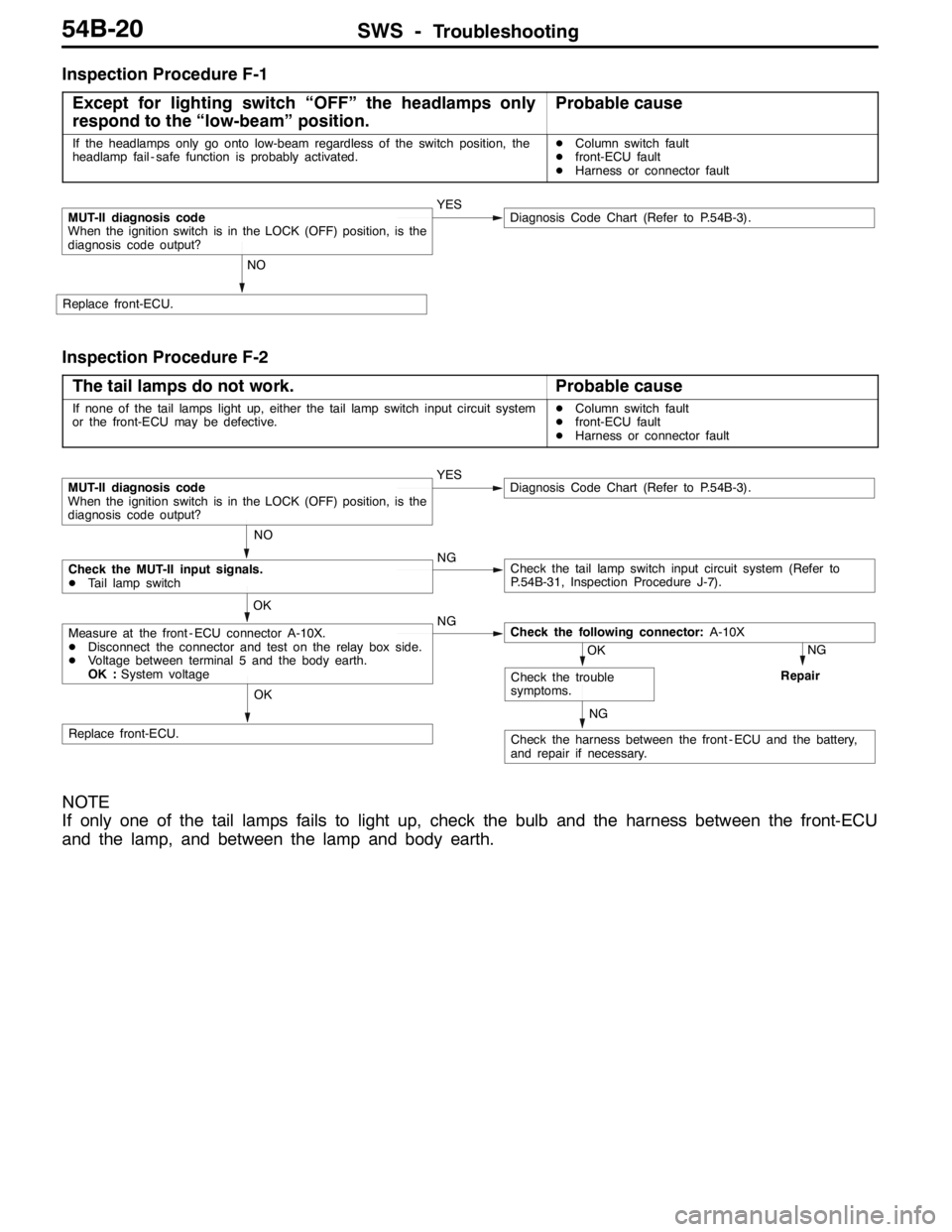
Inspection Procedure F-1
Except for lighting switch “OFF” the headlamps only
respond to the “low-beam” position.
Probable cause
If the headlamps only go onto low-beam regardless of the switch position, the
headlamp fail - safe function is probably activated.DColumn switch fault
Dfront-ECU fault
DHarness or connector fault
NO
Replace front-ECU.
MUT-II diagnosis code
When the ignition switch is in the LOCK (OFF) position, is the
diagnosis code output?YESDiagnosis Code Chart (Refer to P.54B-3).
Inspection Procedure F-2
The tail lamps do not work.
Probable cause
If none of the tail lamps light up, either the tail lamp switch input circuit system
or the front-ECU may be defective.DColumn switch fault
Dfront-ECU fault
DHarness or connector fault
NG
Repair
NG
Check the harness between the front - ECU and the battery,
and repair if necessary.
OK
Replace front-ECU.
OK
Check the trouble
symptoms.
OK
Measure at the front - ECU connector A-10X.
DDisconnect the connector and test on the relay box side.
DVoltage between terminal 5 and the body earth.
OK :System voltageNGCheck the following connector:A-10X
NO
Check the MUT-II input signals.
DTail lamp switchNGCheck the tail lamp switch input circuit system (Refer to
P.54B-31, Inspection Procedure J-7).
MUT-II diagnosis code
When the ignition switch is in the LOCK (OFF) position, is the
diagnosis code output?YESDiagnosis Code Chart (Refer to P.54B-3).
NOTE
If only one of the tail lamps fails to light up, check the bulb and the harness between the front-ECU
and the lamp, and between the lamp and body earth.
Page 1404 of 1449

ServiceSpecifications/Lubricants/
Special ToolsHEATER, AIR CONDITIONER AND VENTILATION-55-2
SERVICE SPECIFICATIONS
ItemStandard value
Idlid()NP85050Idlingspeed(rpm):NorPrange850±50Idlingspeed(rpm):NorPrange850±50Idlingspeed(rpm):NorPrange850�r50
Idle-up speed (rpm): N or P range850±50
Register resistance (for blower motor)ΩHI - LO (between terminals 1 and 3)2.54g()
HI - ML (between terminals 1 and 6)1.24
HI - MH (between terminals 1 and 4)0.6
Air conditioner compressor air gap mm0.3 – 0.5
Refrigerant temperature switch operating temperature (_C)ContinuitySlightly below 150gppgp()
No continuity150 or higher (until tempera-
ture falls to 120 when OFF)
NOTE* : When disconnected the compressor connector at A/C ON
LUBRICANTS
ItemsSpecified lubricantsQuantity
Compressor oil mLSUN PAG 56130±10
Pipe couplingSUN PAG 56As required
Refrigerant (g)R134a (HFC-134a)550±20
SPECIAL TOOLS
ToolNumberNameUse
MB991367Special spannerFor use on the air conditioner compressor
armature locknut
MB991386Pin
MB991529Diagnosis code
check harnessFor inspecting the air conditioner using a
voltmeter
Page 1417 of 1449

HEATER, AIR CONDITIONER AND VENTILATION–On-vehicle Service55-15
COMPRESSOR DRIVE BELT ADJUSTMENT
Refer to GROUP 11 - On-vehicle Service.
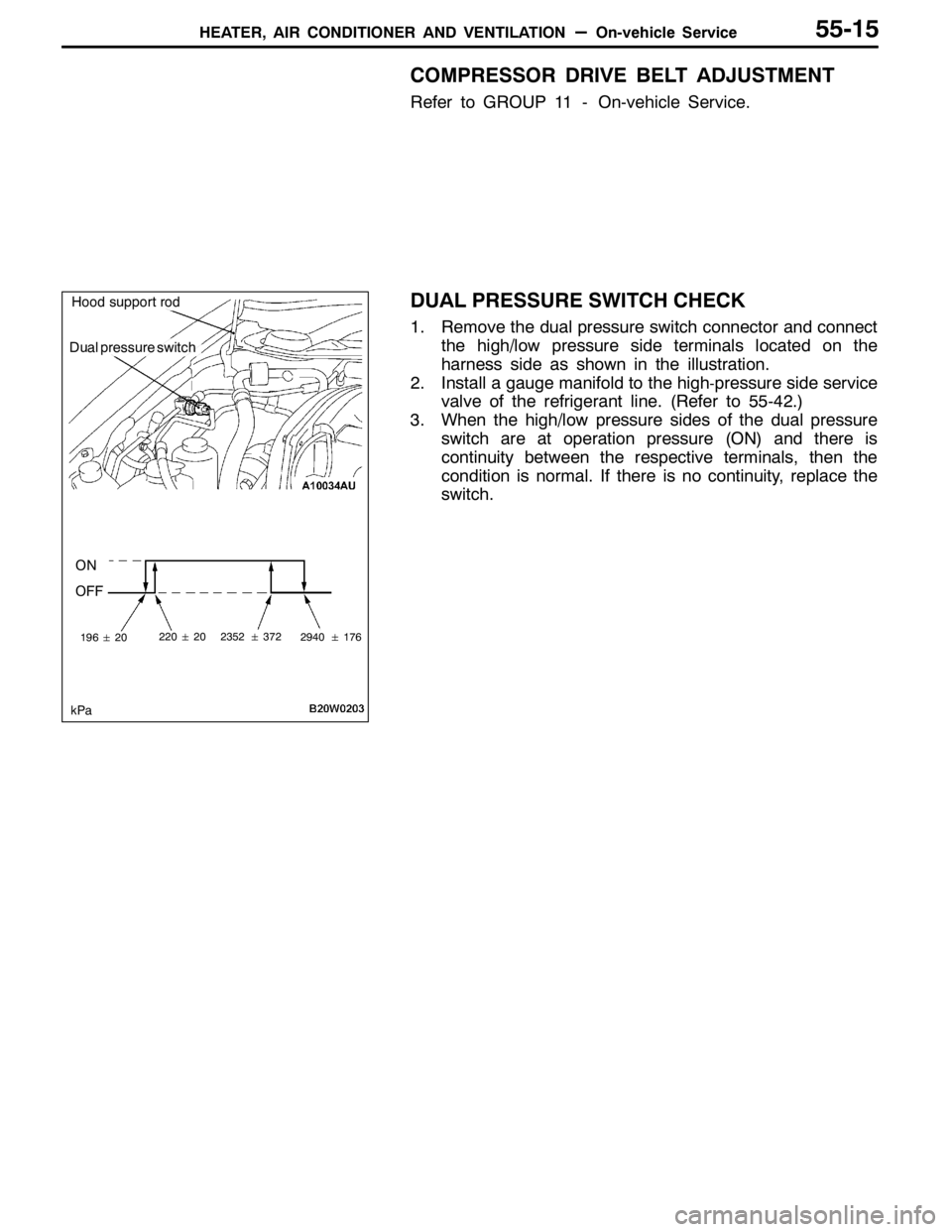
DUAL PRESSURE SWITCH CHECK
1. Remove the dual pressure switch connector and connect
the high/low pressure side terminals located on the
harness side as shown in the illustration.
2. Install a gauge manifold to the high
-pressure side service
valve of the refrigerant line. (Refer to 55-42.)
3. When the high/low pressure sides of the dual pressure
switch are at operation pressure (ON) and there is
continuity between the respective terminals, then the
condition is normal. If there is no continuity, replace the
switch.
Dual pressure switch
ON
OFF
19620
kPa
2202023523722940176
Hood support rod
Page 1423 of 1449

HEATER, AIR CONDITIONER AND VENTILATION–On-vehicle Service55-21
REFRIGERANT LEAK REPAIR
LOST CHARGE
If the system has lost all charge due to a leak:
1. Evacuate the system. (See procedure.)
2. Charge the system with approximately one
pound of refrigerant.
3. Check for leaks.
4. Discharge the system.
5. Repair leaks.
6. Replace receiver drier.
Caution
Replacement filter-drier units must be
sealed while in storage. The drier used in
these units will saturate water quickly upon
exposure to the atmosphere. When
installing a drier, have all tools and supplies
ready for quick reassembly to avoid keeping
the system open any longer than necessary.
7. Evacuate and charge system.
LOW CHARGE
If the system has not lost all of its refrigerant charge;
locate and repair all leaks. If it is necessary to
increase the system pressure to find the leak
(because of an especially low charge) add
refrigerant. If it is possible to repair the leak without
discharging the refrigerant system, use the
procedure for correcting low refrigerant level.HANDLING TUBING AND FITTINGS
Kinks in the refrigerant tubing or sharp bends in
the refrigerant hose lines will greatly reduce the
capacity of the entire system. High pressures are
produced in the system when it is operating.
Extreme care must be exercised to make sure that
all connections are pressure tight. Dirt and moisture
can enter the system when it is opened for repair
or replacement of lines or components. The
following precautions must be observed. The
system must be completely discharged before
opening any fitting of connection in the refrigeration
system. Open fittings with caution even after the
system has been discharged. If any pressure is
noticed as a fitting is loosened, allow trapped
pressure to bleed off very slowly.
Never attempt to rebend formed lines to fit. Use
the correct line for the installation you are servicing.
A good rule for the flexible hose lines is keep the
radius of all bends at least 10 times the diameter
of the hose.
Sharper bends will reduce the flow of refrigerant.
The flexible hose lines should be routed so that
they are at least 80 mm from the exhaust manifold.
It is good practice to inspect all flexible hose lines
at least once a year to make sure they are in good
condition and properly routed.
Unified plumbing connections with O-rings, these
O-rings are not reusable.
COMPRESSOR NOISE
You must first know the conditions when the noise
occurs. These conditions are: weather, vehicle
speed, in gear or neutral, engine temperature or
any other special conditions.
Noises that develop during A/C operation can often
be misleading. For example: what sounds like a
failed front bearing or connecting rod, may be
caused by loose bolts, nuts, mounting brackets,
or a loose clutch assembly. Verify accessory drive
belt tension (power steering or alternator).
Improper accessory drive belt tension can cause
a misleading noise when the compressor is
engaged and little or no noise when the compressor
is disengaged.
Drive belts are speed-sensitive. That is, at different
engine speeds, and depending upon belt tension,
belts can develop unusual noises that are often
mistaken for mechanical problems within the
compressor.ADJUSTMENT
1. Select a quiet area for testing. Duplicate
conditions as much as possible. Switch
compressor on and off several times to clearly
identify compressor noise. To duplicate high
ambient conditions (high head pressure),
restrict air flow through condenser. Install
manifold gauge set to make sure discharge
pressure doesn’t exceed 2,070 kPa.
2. Tighten all compressor mounting bolts, clutch
mounting bolt, and compressor drive belt.
Check to assure clutch coil is tight (no rotation
or wobble).
3. Check refrigerant hoses for rubbing or
interference that can cause unusual noises.
4. Check refrigerant charge. (See “Charging
System”.)
5. Recheck compressor noise as in Step 1.
6. If noise still exists, loosen compressor mounting
bolts and retorque. Repeat Step 1.
7. If noise continues, replace compressor and
repeat Step 1.