2007 MITSUBISHI LANCER EVOLUTION battery
[x] Cancel search: batteryPage 463 of 1449

ENGINE OVERHAUL -Special Tools11B-9
SPECIAL TOOLS
ToolNumberNameUse
MD998781Flywheel stopperFixing of flywheel
MD998778Crankshaft
sprocketRemoval of crankshaft sprocket and
crankshaft sprocket B
MB998785Sprocket stopperHolding of counter balance shaft sprocket
MB991704Battery harnessMeasurement of timing belt B tension
(Use together with MUT-II.)
MB991502MUT-IIsub
assemblyMeasurement of timing belt B tension
(Use together with MB991704 and
MB991668.)
MB991668Belt tension meter
setMeasurement of timing belt B tension
(Use together with MUT-II.)
MD998767Tension pulley
socket wrenchOperation of tensioner pulley during adjust-
ment of timing belt tension
MD998738Set screwHolding of tensioner arm and auto tensioner
during installation of timing belt
MD998713Camshaft oil seal
installerInstallation of camshaft oil seal
Page 472 of 1449

ENGINE OVERHAUL -Timing Belt11B-18
3. Confirm that the tensioner B centre and bolt centre are
positioned as shown in the illustration.
4. Apply tension on the timing belt by lifting tensioner B
in the direction of the arrow with a finger, and tension
the tension side until it is “tight”. Fix tensioner B in this
state by tightening the bolt.
NOTE
Make sure that the tensioner B shaft does not rotate
when tightening the bolt. If the shaft rotates, the timing
belt becomes too tense.
5. Connect the special tool (MB991704) to MUT-IIand the
battery.
6. Connect the special tool (MB991668) to MUT-II.
7. Rotate the crankshaft clockwise two turns, and align each
timing mark.
8. Select “Belt Tension Measurement” from the MUT-IImenu
screen.
9. Separate the special tool (MB991668) 10 to 20 mm from
the centre back between the sprockets (shown with an
arrow), and hold so that it is vertical (inclination within
±15_) in respect to the belt.
10. Lightly tap the section shown with an arrow with fingers,
and measure the belt vibration frequency. If the results
are deviated from the standard value, loosen the bolt,
tension the belt again, and then measure the vibration
frequency again. Repeat this step until the standard value
is attained. Tighten the bolt when the standard value
is attained.
Standard value:
ItemWhen
checkWhen
adjustedWhen
replaced
Vibration frequency Hz52 - 9276 - 9276 - 92
Deflection
(Reference value) mm5-105-75-7
Tensioner
B centre
Installation
bolt centre
Timing
belt B
Belt tension side
Tensioner
B
MB991668
15_ 15_
10 - 20 mm
Page 544 of 1449

MPI -Troubleshooting13A-12
INSPECTION CHART FOR DIAGNOSIS CODES
Code No.Diagnosis itemReference page
P0100Air flow sensor system13A-13
P0105Barometric pressure sensor system13A-15
P0110Intake air temprature sensor system13A-16
P0115Engine coolant temperature sensor system13A-19
P0120Throttle position sensor system13A-21
P0130Oxygen sensor (front) system13A-24
P0135Oxygen sensor heater (front) system13A-26
P0136Oxygen sensor (rear) system13A-27
P0141Oxygen sensor heater (rear) system13A-29
P0201No.1 injector system13A-30
P0202No.2 injector system13A-31
P0203No.3 injector system13A-32
P0204No.4 injector system13A-33
P0325Detonation sensor system13A-34
P0335Crank angle sensor system13A-35
P0340Camshaft position sensor system13A-37
P0403EGR control solenoid valve system13A-39
P0443Purge control solenoid valve system13A-41
P0500Vehicle speed sensor system13A-43
P0505Idle speed control system13A-44
P0551Power steering fluid pressure switch system13A-46
P1104Waste gate solenoid valve system13A-47
P1105Fuel pressure control valve system13A-48
P1500Alternator FR terminal system13A-49
P1603Battery backup line malfunction13A-50
P1610Immobilizer system13A-51
Page 558 of 1449

MPI -Troubleshooting13A-26
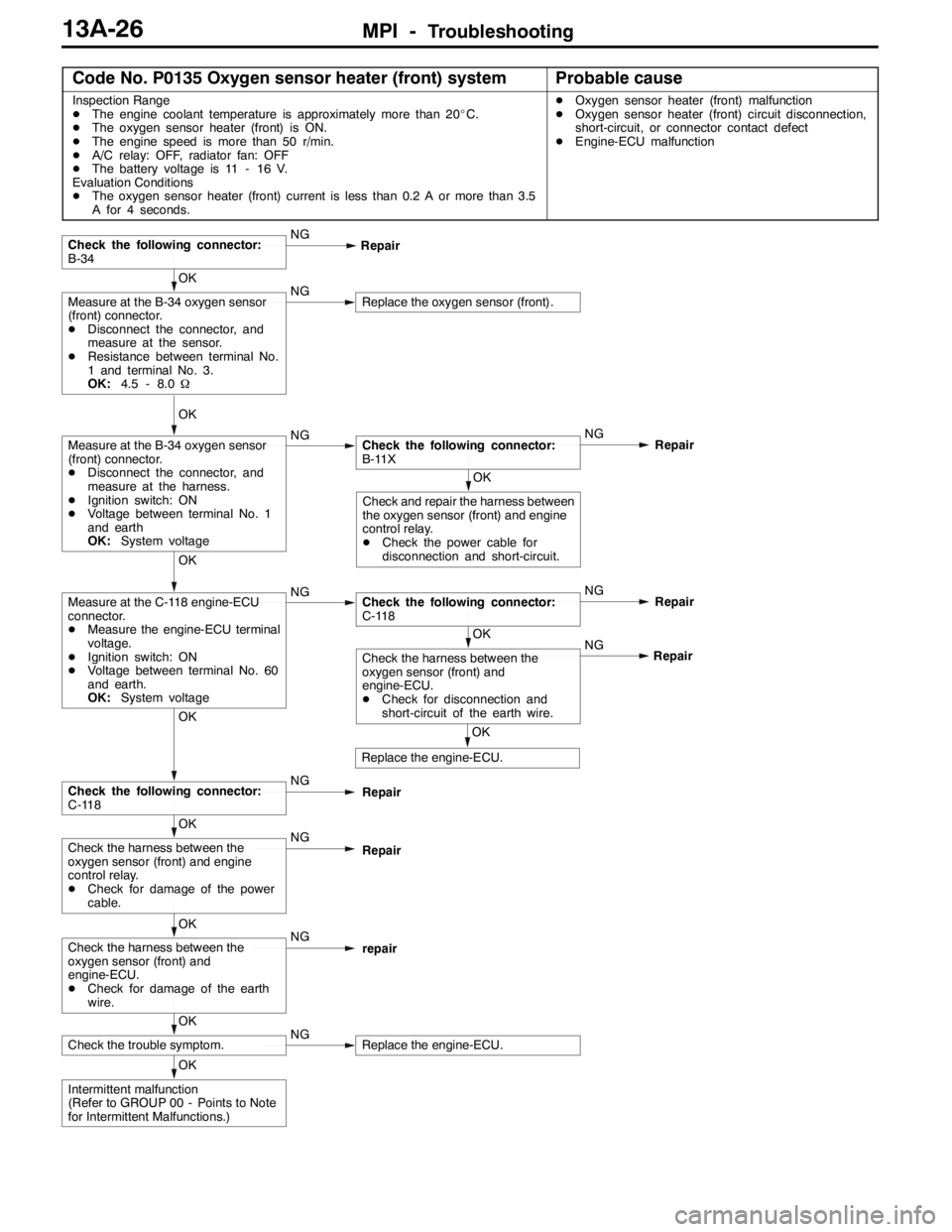
Code No. P0135 Oxygen sensor heater (front) systemProbable cause
Inspection Range
DThe engine coolant temperature is approximately more than 20_C.
DThe oxygen sensor heater (front) is ON.
DThe engine speed is more than 50 r/min.
DA/C relay: OFF, radiator fan: OFF
DThe battery voltage is 11 - 16 V.
Evaluation Conditions
DThe oxygen sensor heater (front) current is less than 0.2 A or more than 3.5
A for 4 seconds.DOxygen sensor heater (front) malfunction
DOxygen sensor heater (front) circuit disconnection,
short-circuit, or connector contact defect
DEngine-ECU malfunction
OK
Intermittent malfunction
(Refer to GROUP 00 - Points to Note
for Intermittent Malfunctions.)
OK
Check the trouble symptom.NGReplace the engine-ECU.
OK
Check the harness between the
oxygen sensor (front) and
engine-ECU.
DCheck for damage of the earth
wire.NG
repair
OK
Check the harness between the
oxygen sensor (front) and engine
control relay.
DCheck for damage of the power
cable.NG
Repair
OK
Check the following connector:
C-118NG
Repair
OK
Replace the engine-ECU.NG
OK
Check the harness between the
oxygen sensor (front) and
engine-ECU.
DCheck for disconnection and
short-circuit of the earth wire.Repair
OK
Measure at the C-118 engine-ECU
connector.
DMeasure the engine-ECU terminal
voltage.
DIgnition switch: ON
DVoltage between terminal No. 60
and earth.
OK:System voltageNGCheck the following connector:
C-118NG
Repair
OK
Check and repair the harness between
the oxygen sensor (front) and engine
control relay.
DCheck the power cable for
disconnection and short-circuit.
OK
Measure at the B-34 oxygen sensor
(front) connector.
DDisconnect the connector, and
measure at the harness.
DIgnition switch: ON
DVoltage between terminal No. 1
and earth
OK:System voltageNGCheck the following connector:
B-11XNG
Repair
OK
Measure at the B-34 oxygen sensor
(front) connector.
DDisconnect the connector, and
measure at the sensor.
DResistance between terminal No.
1 and terminal No. 3.
OK:4.5 - 8.0ΩNGReplace the oxygen sensor (front).
Check the following connector:
B-34NG
Repair
Page 561 of 1449

MPI -Troubleshooting13A-29
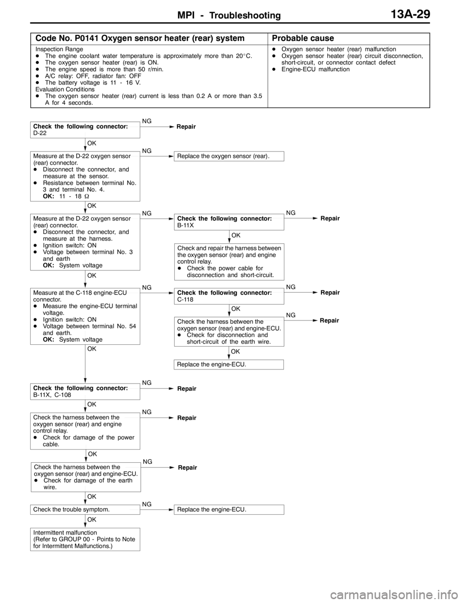
Code No. P0141 Oxygen sensor heater (rear) systemProbable cause
Inspection Range
DThe engine coolant water temperature is approximately more than 20_C.
DThe oxygen sensor heater (rear) is ON.
DThe engine speed is more than 50 r/min.
DA/C relay: OFF, radiator fan: OFF
DThe battery voltage is 11 - 16 V.
Evaluation Conditions
DThe oxygen sensor heater (rear) current is less than 0.2 A or more than 3.5
A for 4 seconds.DOxygen sensor heater (rear) malfunction
DOxygen sensor heater (rear) circuit disconnection,
short-circuit, or connector contact defect
DEngine-ECU malfunction
OK
Intermittent malfunction
(Refer to GROUP 00 - Points to Note
for Intermittent Malfunctions.)
OK
Check the trouble symptom.NGReplace the engine-ECU.
OK
Check the harness between the
oxygen sensor (rear) and engine-ECU.
DCheck for damage of the earth
wire.NG
Repair
OK
Check the harness between the
oxygen sensor (rear) and engine
control relay.
DCheck for damage of the power
cable.NG
Repair
OK
Check the following connector:
B-11X, C-108NG
Repair
OK
Replace the engine-ECU.NG
OK
Check the harness between the
oxygen sensor (rear) and engine-ECU.
DCheck for disconnection and
short-circuit of the earth wire.Repair
OK
Measure at the C-118 engine-ECU
connector.
DMeasure the engine-ECU terminal
voltage.
DIgnition switch: ON
DVoltage between terminal No. 54
and earth.
OK:System voltageNGCheck the following connector:
C-118NG
Repair
OK
Check and repair the harness between
the oxygen sensor (rear) and engine
control relay.
DCheck the power cable for
disconnection and short-circuit.
OK
Measure at the D-22 oxygen sensor
(rear) connector.
DDisconnect the connector, and
measure at the harness.
DIgnition switch: ON
DVoltage between terminal No. 3
and earth
OK:System voltageNGCheck the following connector:
B-11XNG
Repair
OK
Measure at the D-22 oxygen sensor
(rear) connector.
DDisconnect the connector, and
measure at the sensor.
DResistance between terminal No.
3 and terminal No. 4.
OK:11 - 1 8ΩNGReplace the oxygen sensor (rear).
Check the following connector:
D-22NG
Repair
Page 571 of 1449

MPI -Troubleshooting13A-39
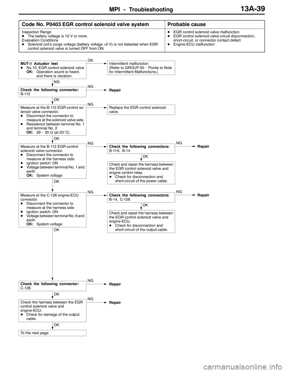
Code No. P0403 EGR control solenoid valve systemProbable cause
Inspection Range
DThe battery voltage is 10 V or more.
Evaluation Conditions
DSolenoid coil’s surge voltage (battery voltage +2 V) is not detected when EGR
control solenoid valve is turned OFF from ON.DEGR control solenoid valve malfunction
DEGR control solenoid valve circuit disconnection,
short-circuit, or connector contact defect
DEngine-ECU malfunction
OK
To the next page
OK
Check the harness between the EGR
control solenoid valve and
engine-ECU.
DCheck for damage of the output
cable.NG
Repair
OK
Check the following connector:
C-126NG
Repair
OK
Check and repair the harness between
the EGR control solenoid valve and
engine-ECU.
DCheck for disconnection and
short-circuit of the output cable.
OK
Measure at the C-126 engine-ECU
connector.
DDisconnect the connector to
measure at the harness side
DIgnition switch: ON
DVoltage between terminal No. 6 and
earth
OK:System voltageNGCheck the following connectors:
B-14, C-126NG
Repair
OK
Check and repair the harness between
the EGR control solenoid valve and
engine control relay.
DCheck for disconnection and
short-circuit of the power cable.
OK
Measure at the B-112 EGR control
solenoid valve connector.
DDisconnect the connector to
measure at the harness side.
DIgnition switch: ON
DVoltage between terminal No. 1 and
earth
OK:System voltageNGCheck the following connectors:
B-11X, B-14NG
Repair
OK
Measure at the B-112 EGR control so-
lenoid valve connector.
DDisconnect the connector to
measure at the solenoid valve side.
DResistance between terminal No. 1
and terminal No. 2
OK:29 - 35Ω(at 20_C)NGReplace the EGR control solenoid
valve.
NG
Check the following connector:
B-112NG
Repair
MUT-IIActuator test
DNo.10: EGR control solenoid valve
OK:Operation sound is heard,
and there is vibration.OKIntermittent malfunction
(Refer to GROUP 00 - Points to Note
for Intermittent Malfunctions.)
Page 573 of 1449

MPI -Troubleshooting13A-41
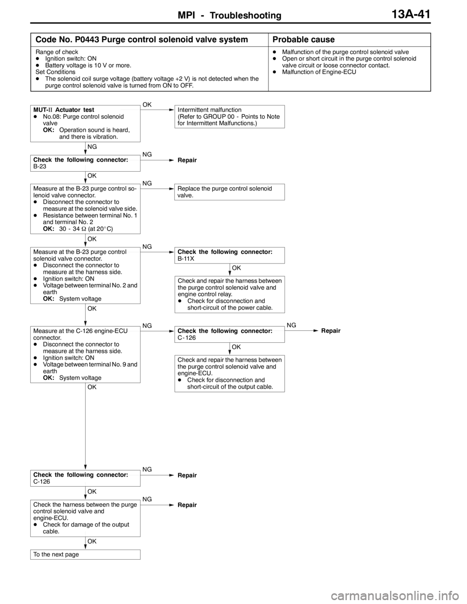
Code No. P0443 Purge control solenoid valve systemProbable cause
Range of check
DIgnition switch: ON
DBattery voltage is 10 V or more.
Set Conditions
DThe solenoid coil surge voltage (battery voltage +2 V) is not detected when the
purge control solenoid valve is turned from ON to OFF.DMalfunction of the purge control solenoid valve
DOpen or short circuit in the purge control solenoid
valve circuit or loose connector contact.
DMalfunction of Engine-ECU
OK
To the next page
OK
Check the harness between the purge
control solenoid valve and
engine-ECU.
DCheck for damage of the output
cable.NG
Repair
OK
Check the following connector:
C-126NG
Repair
OK
Check and repair the harness between
the purge control solenoid valve and
engine-ECU.
DCheck for disconnection and
short-circuit of the output cable.
OK
Measure at the C-126 engine-ECU
connector.
DDisconnect the connector to
measure at the harness side.
DIgnition switch: ON
DVoltage between terminal No. 9 and
earth
OK:System voltageNGCheck the following connector:
C - 126NG
Repair
OK
Check and repair the harness between
the purge control solenoid valve and
engine control relay.
DCheck for disconnection and
short-circuit of the power cable.
OK
Measure at the B-23 purge control
solenoid valve connector.
DDisconnect the connector to
measure at the harness side.
DIgnition switch: ON
DVoltage between terminal No. 2 and
earth
OK:System voltageNGCheck the following connector:
B-11X
OK
Measure at the B-23 purge control so-
lenoid valve connector.
DDisconnect the connector to
measure at the solenoid valve side.
DResistance between terminal No. 1
and terminal No. 2
OK:30 - 34Ω(at 20_C)NGReplace the purge control solenoid
valve.
NG
Check the following connector:
B-23NG
Repair
MUT-IIActuator test
DNo.08: Purge control solenoid
valve
OK:Operation sound is heard,
and there is vibration.OKIntermittent malfunction
(Refer to GROUP 00 - Points to Note
for Intermittent Malfunctions.)
Page 576 of 1449

MPI -Troubleshooting13A-44
Code No. P0505 Idle speed control systemProbable cause
Range of Check
DVehicle speed has reached 1.5 Km/h at least once.
DUnder the closed loop idle speed control.
Set Conditions
DActual idle speed has continued to be higher than the target idle speed by 300
r/min or more for 10 seconds.
Range fo Check
DVehicle speed has reached 1.5 km/h at least once.
DDuring idle speed closed loop control.
DThe highest temperature at the last drive is 45_C or less.
DEngine coolant temperature is approximately 80_C or more.
DBattery voltage is 10 V or more.
DBarometric pressure is 76 kPa or higher.
DIntake air temperature is - 10_C or more.
Set Conitions
DActual idle speed has been minimum 200 r/min higher than the target idle speed
for 10 seconds.
Range of Check
DDuring idle speed closed loop control.
DEngine coolant temperature is approximately 80_C or higher.
DBattery voltage is 10 V or higher.
DPower steering switch is off.
DVolumetric efficiency is 40 % or lower.
DBarometric pressure is 76 kPa or higher.
DIntake air temperature is - 10_C or more.
Set Conitions
DActual idle speed has been minimum 100 r/min higher than the target idle speed
for 10 seconds.DMalfunction of idle speed control servo
DOpen or short circuit in the idle speed control servo
circuit or loose connector contact
DMalfunction of engine-ECU