2007 MITSUBISHI LANCER EVOLUTION battery
[x] Cancel search: batteryPage 657 of 1449

MPI -On-vehicle Service13A-125
ON-VEHICLE SERVICE
FUEL PUMP CONNECTOR DISCONNECTION
(HOW TO REDUCE THE FUEL PRESSURE)
When removing the fuel pipe, hose, etc., since fuel pressure
in the fuel pipe line is high, do the following operation so
as to release the fuel pressure in the line and prevent fuel
from running out.
1. Remove the rear seat assembly. (Refer to GROUP 52A.)
2. Remove the protector.
3. Disconnect the fuel pump module connector.
4. After starting the engine and letting it run until it stops
naturally, turn the ignition switch to “LOOK” (OFF) position.
5. Connect the fuel pump module connector.
6. Install the protector and rear seat assembly.
(Refer to GROUP 52A.)
FUEL PUMP OPERATION CHECK
1. Check the operation of the fuel pump by using the MUT-II
to force-drive the fuel pump.
2. If the fuel pump will not operate, check by using the
following procedure, and if it is normal, check the drive
circuit.
(1) Turn the ignition switch to “LOOK” (OFF) position.
(2) Remove the rear seat assembly. (Refer to GROUP
52A.)
(3) Remove the protector.
(4) Disconnect the fuel pump module connector.
(5) When the fuel pump drive connector is attached
directly to the battery, check if the sound of the fuel
pump operation can be heard.
NOTE
As the fuel pump is an in-tank type, the fuel pump
sound is hard to hear, so remove the fuel filler cap
and check from the tank inlet.
(6) Check the fuel pressure by pinching the fuel hose
with the fingertips.
(7) Connect the fuel pump module connector.
(8) Install the protector and rear seat assembly. (Refer
to GROUP 52A.)
Page 659 of 1449

MPI -On-vehicle Service13A-127
4. If not within the standard value, loosen the throttle position
sensor mounting bolts. Then rotate the sensor body to
adjust.
5. Turn the ignition switch to “LOCK” (OFF) position.
6. Remove the MUT-II. If the MUT-IIis not used, remove
the special tool, and then connect the throttle position
sensor connector.
7. If a diagnosis code is displayed, erase the diagnosis code
by using the MUT-IIor disconnect the negative battery
cable from the battery terminal and then leave it for at
least ten seconds. After that, reconnect the battery cable,
and then let the engine run at idle for approximately 10
minutes.
BASIC IDLE SPEED ADJUSTMENT
NOTE
(1) The basic idling speed has been adjusted by the
speed adjusting screw by the manufacturer, and there
should usually be no need for readjustment.
(2) If the adjustment has been changed by mistake, the
idle speed may become too high or the idle speed
may drop too low when loads from components such
as the A/C are placed on the engine. If this occurs,
adjust by the following procedure.
(3) The adjustment, if made, should be made after first
confirming that the spark plugs, the injectors, the idle
speed control servo, the compression pressure, etc.,
are all normal.
1. Before inspection and adjustment, set the vehicle to the
pre-inspection condition.
2. Connect the MUT-IIto the diagnosis connector (16-pin).
NOTE
When the MUT-IIis connected, the diagnosis control
terminal should be earthed.
3. Start the engine and run at idle.
4. Select the item No. 30 of the MUT-IIActuator test.
NOTE
This holds the idle speed control servo at the basic step
to adjust the basic idle speed.
5. Check the basic idle speed.
Standard value: 850±100 r/min
NOTE
(1) The engine speed may be 20 to 100 r/min lower
than indicated above for a new vehicle [driven
approximately 500 km or less], but no adjustment
is necessary.
(2) If the engine stalls or the engine speed is low even
though the vehicle has been driven approximately
500 km or more, it is probable that deposits are
adhered to the throttle valve, so clean it. (Refer to
P.13A-126.)
Page 664 of 1449

MPI -On-vehicle Service13A-132
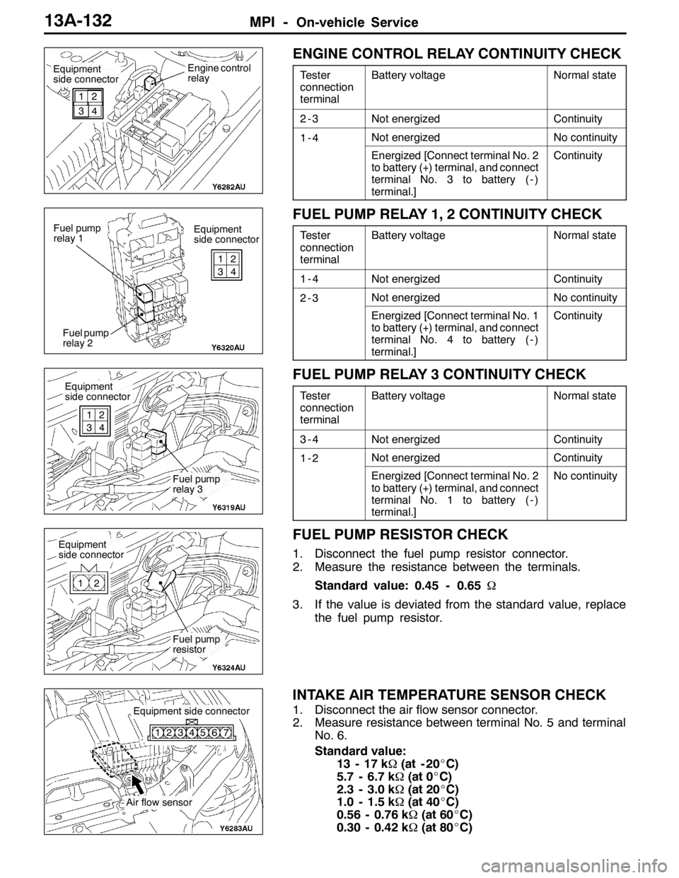
ENGINE CONTROL RELAY CONTINUITY CHECK
Tester
connection
terminalBattery voltageNormal state
2-3Not energizedContinuity
1-4Not energizedNo continuity
Energized [Connect terminal No. 2
to battery (+) terminal, and connect
terminal No. 3 to battery ( - )
terminal.]Continuity
FUEL PUMP RELAY 1, 2 CONTINUITY CHECK
Tester
connection
terminalBattery voltageNormal state
1-4Not energizedContinuity
2-3Not energizedNo continuity
Energized [Connect terminal No. 1
to battery (+) terminal, and connect
terminal No. 4 to battery ( - )
terminal.]Continuity
FUEL PUMP RELAY 3 CONTINUITY CHECK
Tester
connection
terminalBattery voltageNormal state
3-4Not energizedContinuity
1-2Not energizedContinuity
Energized [Connect terminal No. 2
to battery (+) terminal, and connect
terminal No. 1 to battery ( - )
terminal.]No continuity
FUEL PUMP RESISTOR CHECK
1. Disconnect the fuel pump resistor connector.
2. Measure the resistance between the terminals.
Standard value: 0.45 - 0.65Ω
3. If the value is deviated from the standard value, replace
the fuel pump resistor.
INTAKE AIR TEMPERATURE SENSOR CHECK
1. Disconnect the air flow sensor connector.
2. Measure resistance between terminal No. 5 and terminal
No. 6.
Standard value:
13 - 17 kΩ(at - 20_C)
5.7 - 6.7 kΩ(at 0_C)
2.3 - 3.0 kΩ(at 20_C)
1.0 - 1.5 kΩ(at 40_C)
0.56 - 0.76 kΩ(at 60_C)
0.30 - 0.42 kΩ(at 80_C)
Equipment
side connectorEngine control
relay
1
32
4
Equipment
side connector Fuel pump
relay 1
Fuel pump
relay 21
32
4
Equipment
side connector
Fuel pump
relay 3 1
32
4
Equipment
side connector
Fuel pump
resistor 12
Air flow sensor
Equipment side connector
123456 7
Page 667 of 1449

MPI -On-vehicle Service13A-135
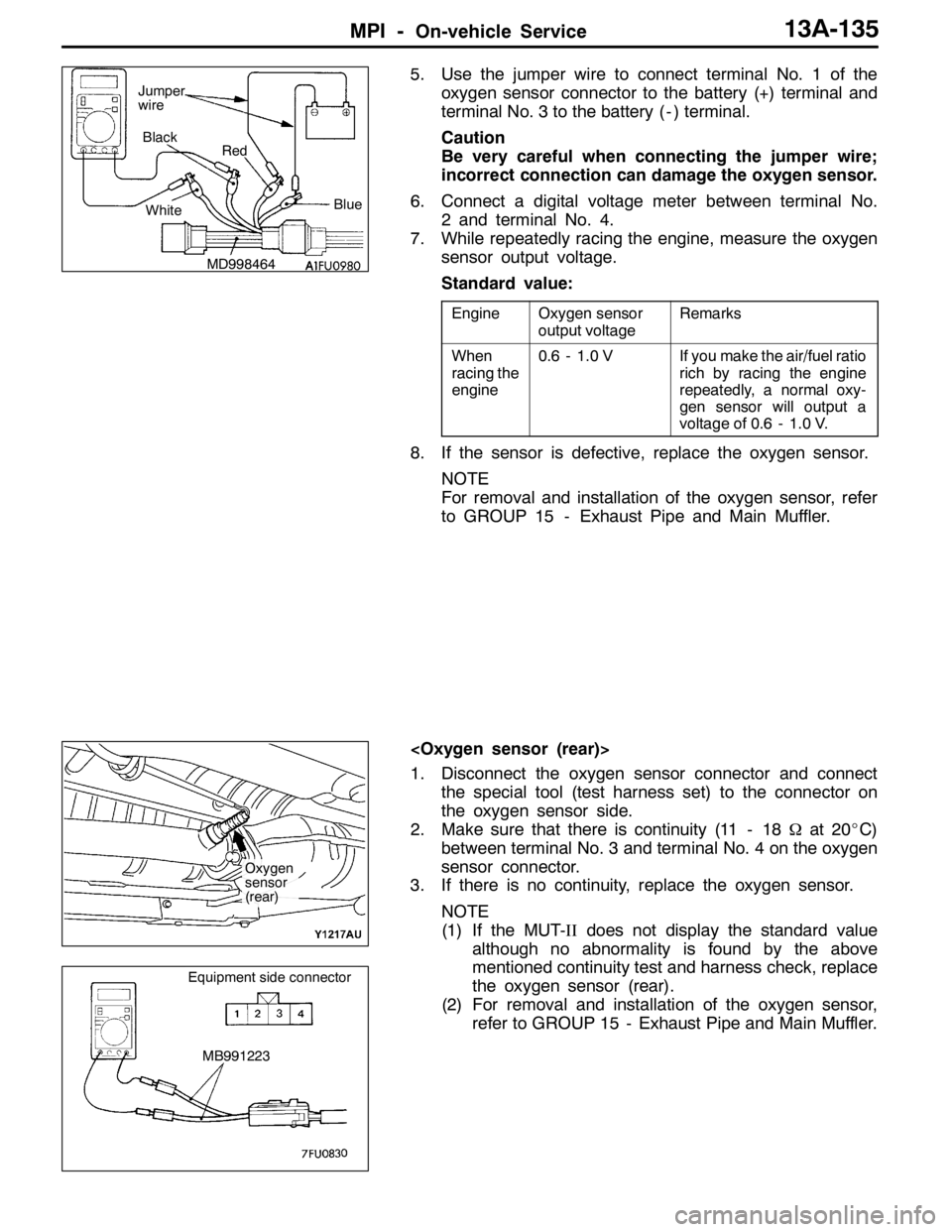
5. Use the jumper wire to connect terminal No. 1 of the
oxygen sensor connector to the battery (+) terminal and
terminal No. 3 to the battery ( - ) terminal.
Caution
Be very careful when connecting the jumper wire;
incorrect connection can damage the oxygen sensor.
6. Connect a digital voltage meter between terminal No.
2 and terminal No. 4.
7. While repeatedly racing the engine, measure the oxygen
sensor output voltage.
Standard value:
EngineOxygen sensor
output voltageRemarks
When
racing the
engine0.6 - 1.0 VIf you make the air/fuel ratio
rich by racing the engine
repeatedly, a normal oxy-
gen sensor will output a
voltage of 0.6 - 1.0 V.
8. If the sensor is defective, replace the oxygen sensor.
NOTE
For removal and installation of the oxygen sensor, refer
to GROUP 15 - Exhaust Pipe and Main Muffler.
1. Disconnect the oxygen sensor connector and connect
the special tool (test harness set) to the connector on
the oxygen sensor side.
2. Make sure that there is continuity (11 - 18Ωat 20_C)
between terminal No. 3 and terminal No. 4 on the oxygen
sensor connector.
3. If there is no continuity, replace the oxygen sensor.
NOTE
(1) If the MUT-IIdoes not display the standard value
although no abnormality is found by the above
mentioned continuity test and harness check, replace
the oxygen sensor (rear).
(2) For removal and installation of the oxygen sensor,
refer to GROUP 15 - Exhaust Pipe and Main Muffler.
MD998464Blue Black
Red
White Jumper
wire
Oxygen
sensor
(rear)
MB991223
Equipment side connector
Page 669 of 1449

MPI -On-vehicle Service13A-137
MB991607
High-pressure fuel hoseMD998741
MD998706Return hose
BatteryInjectorFuel pressure regulator
Clip
(MB991608)
4. Connect the MUT-IIto the diagnosis connector.
5. Turn the ignition switch to “ON” position. (But do not start
the engine.)
6. Select “Item No. 07” from the MUT-IIActuator test to
drive the fuel pump.
7. Activate the injector and check the atomized spray
condition of the fuel.
The condition can be considered satisfactory unless it
is extremely poor.
8. Stop the actuation of the injector, and check for leakage
from the injector’s nozzle.
Standard value: 1 drop or less per minute
9. Activate the injector without activating the fuel pump; then,
when the spray emission of fuel from the injector stops,
disconnect the special tool and restore it to its original
condition.
10. Disconnect the MUT-II.
High-pressure
fuel hose
BatteryInjectorReturn hose
Page 672 of 1449

MPI -On-vehicle Service13A-140
FUEL PRESSURE CONTROL SOLENOID
VALVE CHECK
OPERATION CHECK
1. Disconnect the vacuum hose from the solenoid valve.
2. Separate the harness connector.
3. Connect the hand vacuum pump to the solenoid valve’s
A nipple.
4. Connect the solenoid valve terminal and battery terminal
with a jumper wire.
5. Disconnect the jumper wire between the battery’s ( - )
terminals, apply a negative pressure, and inspect the
tightness.
Standard value:
Jumper wireState of B
nippleNormal state
ConnectedOpenedNegative pressure leaks.
ClosedNegative pressure is
maintained.
DisconnectedOpenedNegative pressure is
maintained.
COIL RESISTANCE CHECK
Measure the resistance between the solenoid valve terminals.
Standard value: 28 – 36Ω(at 20_C)
PURGE CONTROL SOLENOID VALVE CHECK
Refer to GROUP 17 - Emission Control System.
EGR CONTROL SOLENOID VALVE CHECK
Refer to GROUP 17 - Emission Control System.
Fuel pres-
sure control
solenoid
valve
Battery
Page 692 of 1449

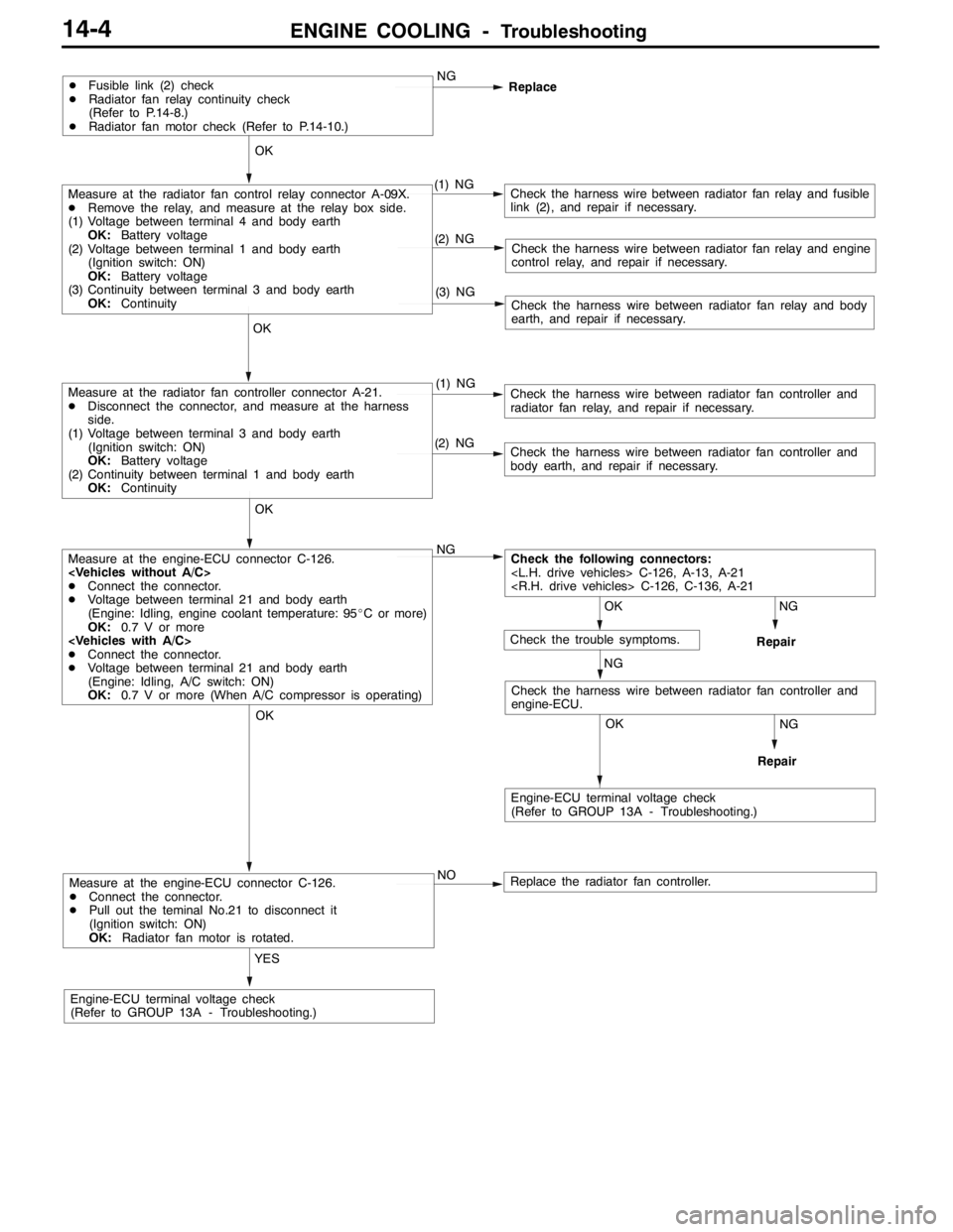
ENGINE COOLING -Troubleshooting14-4
Measure at the engine-ECU connector C-126.
DConnect the connector.
DPull out the teminal No.21 to disconnect it
(Ignition switch: ON)
OK:Radiator fan motor is rotated.
YES
Engine-ECU terminal voltage check
(Refer to GROUP 13A - Troubleshooting.)NO
Replace the radiator fan controller.
NG
Repair
OK
NG
Repair
OK
Check the harness wire between radiator fan controller and
engine-ECU.
Measure at the engine-ECU connector C-126.
DConnect the connector.
DVoltage between terminal 21 and body earth
(Engine: Idling, engine coolant temperature: 95_C or more)
OK:0.7 V or more
DConnect the connector.
DVoltage between terminal 21 and body earth
(Engine: Idling, A/C switch: ON)
OK:0.7 V or more (When A/C compressor is operating)NG
(2) NGCheck the harness wire between radiator fan controller and
body earth, and repair if necessary.
OK
Measure at the radiator fan controller connector A-21.
DDisconnect the connector, and measure at the harness
side.
(1) Voltage between terminal 3 and body earth
(Ignition switch: ON)
OK:Battery voltage
(2) Continuity between terminal 1 and body earth
OK:Continuity(1) NGCheck the harness wire between radiator fan controller and
radiator fan relay, and repair if necessary.
(3) NGCheck the harness wire between radiator fan relay and body
earth, and repair if necessary.
(2) NGCheck the harness wire between radiator fan relay and engine
control relay, and repair if necessary.
OK
Measure at the radiator fan control relay connector A-09X.
DRemove the relay, and measure at the relay box side.
(1) Voltage between terminal 4 and body earth
OK:Battery voltage
(2) Voltage between terminal 1 and body earth
(Ignition switch: ON)
OK:Battery voltage
(3) Continuity between terminal 3 and body earth
OK:Continuity(1) NGCheck the harness wire between radiator fan relay and fusible
link (2), and repair if necessary.
DFusible link (2) check
DRadiator fan relay continuity check
(Refer to P.14-8.)
DRadiator fan motor check (Refer to P.14-10.)NG
Replace
OK
OK
Engine-ECU terminal voltage check
(Refer to GROUP 13A - Troubleshooting.)
Check the following connectors:
NG
Check the trouble symptoms.
Page 696 of 1449

ENGINE COOLING -On-vehicle Service14-8
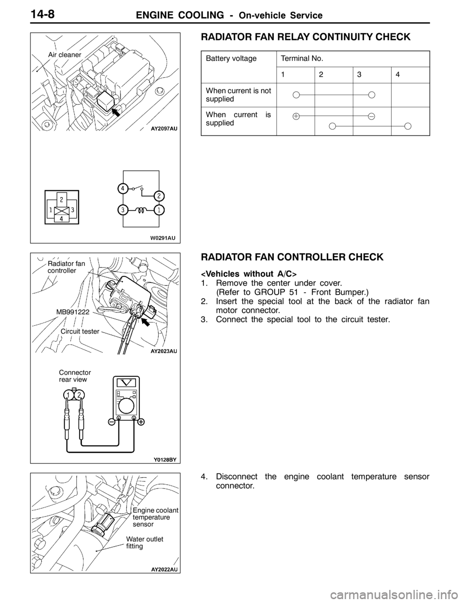
RADIATOR FAN RELAY CONTINUITY CHECK
Battery voltageTerminal No.
1234
When current is not
supplied
When current is
supplied
RADIATOR FAN CONTROLLER CHECK
1. Remove the center under cover.
(Refer to GROUP 51 - Front Bumper.)
2. Insert the special tool at the back of the radiator fan
motor connector.
3. Connect the special tool to the circuit tester.
4. Disconnect the engine coolant temperature sensor
connector.
Air cleaner
Radiator fan
controller
MB991222
Circuit tester
Connector
rear view
Water outlet
fitting
Engine coolant
temperature
sensor