Page 697 of 1449
![MITSUBISHI LANCER EVOLUTION 2007 Service Repair Manual ENGINE COOLING -On-vehicle Service14-9
5. Connect the special tool (MB991658) to the harness side
of the engine coolant temperature sensor connector.
6. Connect the special tool [MB991791(APS)] to the MITSUBISHI LANCER EVOLUTION 2007 Service Repair Manual ENGINE COOLING -On-vehicle Service14-9
5. Connect the special tool (MB991658) to the harness side
of the engine coolant temperature sensor connector.
6. Connect the special tool [MB991791(APS)] to the](/manual-img/19/57084/w960_57084-696.png)
ENGINE COOLING -On-vehicle Service14-9
5. Connect the special tool (MB991658) to the harness side
of the engine coolant temperature sensor connector.
6. Connect the special tool [MB991791(APS)] to the special
tool (MB991658).
7. Start the engine and let it run at idle.
NOTE
Since the resistance value of the special tool (APS)
indicates a low engine coolant temperature, engine speed
increases.
8. When the lever of the special tool (APS) is turned to
the end, check that the engine speed decreases and
the radiator fan motor rotates.
9. When the lever of the special tool (APS) is turned to
the reverse direction, check that the voltage between
terminals of the radiator fan motor connector gradually
decreases from the battery voltage to 0 V.
10. If inoperable, replace the radiator fan controller.
(Refer to P.14-15.)
11. Install the center under cover.
(Refer to GROUP 51 - Front Bumper.)
12. Connect the engine coolant temperature sensor
connector.
1. Remove the center under cover.
(Refer to GROUP 51 - Front Bumper.)
2. Insert the special tool at the back of the radiator fan
motor connector.
3. Connect the special tool to the circuit tester.
4. Start the engine and run it at idle.
5. Turn the A/C switch to the ON position and hold the
engine coolant temperature at 80_C or lower.
6. When the voltage between the terminals of the radiator
fan motor connector, the following values of (1) - (3)
can be detected at random.
(1) 0 V
(2) 8.22.6 V
(3) Battery voltage2.6 V
7. If inoperable, replace the radiator fan controller.
(Refer to P.14-15.)
8. Install the center under cover.
(Refer to GROUP 51 - Front Bumper.)
Engine coolant
temperature sensor
connector
(harness side)
MB991791(APS)
MB991658
MB991658Lever
MB991791(APS)
Radiator fan
controller
MB991222
Circuit tester
Connector
rear view
Page 698 of 1449
ENGINE COOLING -On - vehicle Service14-10
RADIATOR FAN MOTOR CHECK
1. Remove the center under cover.
(Refer to GROUP 51 - Front Bumper.)
2. Disconnect the radiator fan motor connector.
3. Check that the motor rotates when energizing battery
voltage between the terminals of connectors of the radiator
fan motor side.Check that there is abonormal noise from
the radiator fan motor then.
4. If inoperable, replace the radiator fan motor.
(Refer to P.14-15.)
5. Install the center under cover.
(Refer to GROUP 51 - Front Bumper.)Radiator fan motor
Page 702 of 1449

ENGINE COOLING -Water Hose and Water Pipe14-14
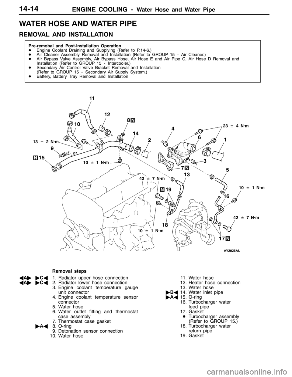
WATER HOSE AND WATER PIPE
REMOVAL AND INSTALLATION
Pre-remobal and Post-installation Operation
DEngine Coolant Draining and Supplying (Refer to P.14-6.)
DAir Cleaner Assembly Removal and Installation (Refer to GROUP 15 - Air Cleaner.)
DAir Bypass Valve Assembly, Air Bypass Hose, Air Hose E and Air Pipe C, Air Hose D Removal and
Installation (Refer to GROUP 15 - Intercooler.)
DSecondary Air Control Valve Bracket Removal and Installation
(Refer to GROUP 15 - Secondary Air Supply System.)
DBattery, Battery Tray Removal and Installation
3 4
5 6
7 8
9
1012
10±1 N·m
42±7 N·m 13±2 N·m
11
1
2
23±4 N·m
18
1716 1514
13
19
10±1 N·m
42±7 N·m
10±1 N·m
Removal steps
AA""CA1. Radiator upper hose connection
AA""CA2. Radiator lower hose connection
3. Engine coolant temperature gauge
unit connector
4. Engine coolant temperature sensor
connector
5. Water hose
6. Water outlet fitting and thermostat
case assembly
7. Thermostat case gasket
"AA8. O-ring
9. Detonation sensor connection
10. Water hose11. Water hose
12. Heater hose connection
13. Water hose
"BA14. Water inlet pipe
"AA15. O-ring
16. Turbocharger water
feed pipe
17. Gasket
DTurbocharger assembly
(Refer to GROUP 15.)
18. Turbocharger water
return pipe
19. Gasket
Page 703 of 1449

ENGINE COOLING -Water Hose and Water Pipe/Radiator14-15
REMOVAL SERVICE POINT
AA"RADIATOR UPPER HOSE/RADIATOR LOWER
HOSE DISCONNECTION
After making mating marks on the hose and the hose clamp,
disconnect the hose.
INSTALLATION SERVICE POINTS
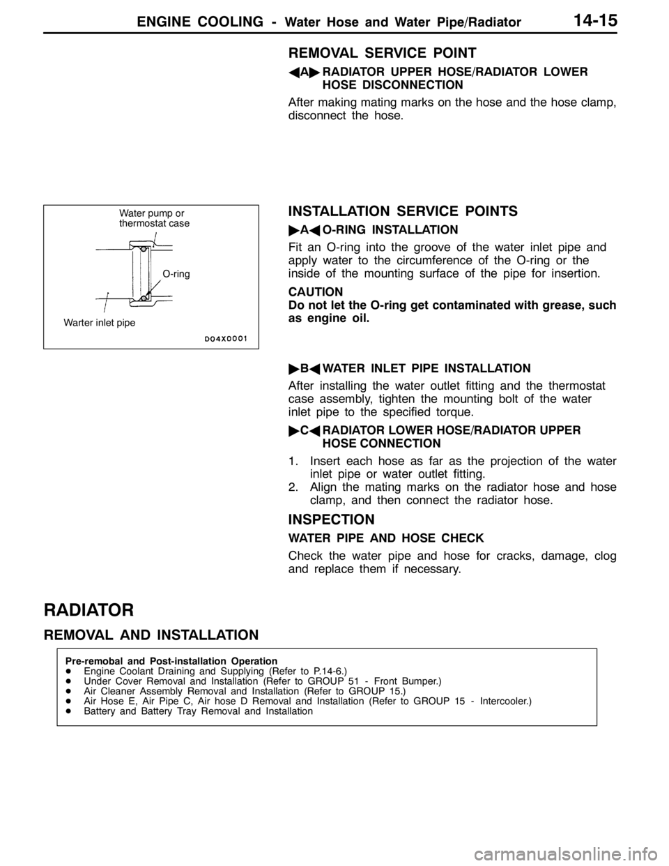
"AAO-RING INSTALLATION
Fit an O-ring into the groove of the water inlet pipe and
apply water to the circumference of the O-ring or the
inside of the mounting surface of the pipe for insertion.
CAUTION
Do not let the O-ring get contaminated with grease, such
as engine oil.
"BAWATER INLET PIPE INSTALLATION
After installing the water outlet fitting and the thermostat
case assembly, tighten the mounting bolt of the water
inlet pipe to the specified torque.
"CARADIATOR LOWER HOSE/RADIATOR UPPER
HOSE CONNECTION
1. Insert each hose as far as the projection of the water
inlet pipe or water outlet fitting.
2. Align the mating marks on the radiator hose and hose
clamp, and then connect the radiator hose.
INSPECTION
WATER PIPE AND HOSE CHECK
Check the water pipe and hose for cracks, damage, clog
and replace them if necessary.
RADIATOR
REMOVAL AND INSTALLATION
Pre-remobal and Post-installation Operation
DEngine Coolant Draining and Supplying (Refer to P.14-6.)
DUnder Cover Removal and Installation (Refer to GROUP 51 - Front Bumper.)
DAir Cleaner Assembly Removal and Installation (Refer to GROUP 15.)
DAir Hose E, Air Pipe C, Air hose D Removal and Installation (Refer to GROUP 15 - Intercooler.)
DBattery and Battery Tray Removal and Installation
Water pump or
thermostat case
O-ring
Warter inlet pipe
Page 711 of 1449

INTAKE AND EXHAUST -On-vehicle Service15-5
3. If there is a significant deviation from the standard value,
check the actuator or the waste gate valve: replace
actuator or turbocharger assembly if necessary.
WASTE GATE SOLENOID VALVE CHECK
OPERATION CHECK
1. Connect a hand vacuum pump to the solenoid valve nipple
A.
2. Using a jumper wire, connect between the solenoid valve
terminal and battery terminal.
3. Connecting and disconnecting the jumper wire at the
battery negative terminal to apply a negative pressure,
check tightness.
Jumper wireB nipple
conditionNormal condition
ConnectedOpenedNegative pressure leaks.
ClosedNegative pressure is held.
DisconnectedOpenedNegative pressure is held.
COIL RESISTANCE CHECK
Measure the resistance between solenoid valve terminals.
Standard value: 29 – 35Ω(at 20_C)
AIR BYPASS VALVE CHECK
1. Remove the air bypass valve.
2. Connect the hand vacuum pump to the nipple of the
air bypass valve.
3. Apply a negative pressure of approximately 49 kPa, and
check that air tightness is maintained.
4. Also check operation of the valve.
Standard value:
Negative pressureValve operation
Approximately 53 kPaIt starts opening
Battery B A
Page 712 of 1449

INTAKE AND EXHAUST -On-vehicle Service15-6
INTAKE MANIFOLD PRESSURE CHECK
Refer to GROUP 11A – On-vehicle Service.
SECONDARY AIR CONTROL SYSTEM CHECK
1. Start the engine and carry out idling.
2. Confirm that the secondary air valve lifts up when the
engine-ECU connector No. 53 terminal is short-circuited
with the earth using a jumper wire.
The engine-ECU connector must be connected at this
time.
SECONDARY AIR CONTROL SOLENOID
VALVE CHECK
OPERATION CHECK
1. Disconnect the vacuum hose (white-striped, yellow-
striped) from the solenoid valve.
2. Separate the harness connector.
3. Connect the hand vacuum pump to the solenoid valve’s
A nipple.
4. Connect the solenoid valve terminal and battery terminal
with a jumper wire.
5. Disconnect the jumper wire between the battery’s ( - )
terminals, apply a negative pressure, and inspect the
tightness.
Jumper wireState of B
nippleNormal state
ConnectedOpenedNegative pressure leaks.
ClosedNegative pressure is
maintained.
DisconnectedClosedNegative pressure leaks.
Vacuum tank
Secondary
air control
solenoid
valve
Battery A B
Page 714 of 1449
INTAKE AND EXHAUST -Air Cleaner15-8
AIR CLEANER
REMOVAL AND INSTALLATION
Caution
Parts marked by * are made of recycled-paper mixed plastic material, so observe the following
precautions.
1. Avoid any shock or load to these parts when removing and installing them.
2. Engage the case hinges securely when assembling these parts.
NOTE
Parts marked by * are made of recycled-paper mixed plastic material, so can be disposed of by incineration.
1
6
*
37
28
5 4
9.0±1.0 N·m 6.0±1.0 N·m
9.0±1.0 N·m
9.0±1.0 N·m 4.0±1.0 N·m
4.0±1.0 N·m
9.0±1.0 N·m
2
9
1011
9.0±1.0 N·m
Removal steps
DBattery
1. Air duct
2. Vacuum hose
DAir pipe E, Air by-pass valve assembly,
Air by-pass hose (Refer to P.15-9.)
3. Air intake hose
4. Air flow sensor assembly5. Gasket
6. Air cleaner assembly
7. Air cleaner cover
8. Air cleaner element
9. Air cleaner body
10. Waste gate solenoid valve
11. Air cleaner bracket
Page 719 of 1449
INTAKE AND EXHAUST -Intercooler Water Spray
ILL
15-13
INSPECTION
1. WATER SPRAY SWITCH CONTINUITY CHECK
SwitchpositionTerminalNoSwitchpositionTerminalNo.p
AUTOMANUALEARTHILL (+)ILL ( - )
12356
AUTO
NEUTRAL
MAN
2. WATER SPRAY MOTOR CHECK
(1) Check the water spray motor with the washer tank
attached after the washer tank is supplied with water.
(2) Check that the water is supplied with strong pressure
after energizing terminal number 1 with battery voltage
and earthing terminal number 2.