2007 MITSUBISHI LANCER EVOLUTION battery
[x] Cancel search: batteryPage 947 of 1449

27B-1
REAR AXLE
CONTENTS
GENERAL INFORMATION 2...................
SERVICE SPECIFICATIONS 3.................
LUBRICANTS 3..............................
SEALANTS 4................................
SPECIAL TOOLS 4...........................
TROUBLESHOOTING (AYC) 8.................
ON-VEHICLE SERVICE 16....................
Rear Axle Total Backlash Check 16...............
Gear Oil Level Check 16........................
Gear Oil Change 17............................
Fluid Level Check 19............................
Bleeding 19....................................
AYC Operation Check 20........................
Oil Pressure Check 21..........................Wheel Bearing Axial Play Check 22...............
Wheel Bearing Rotary-sliding Resistance Check 22.
Hub Bolt Replacement 23.......................
Differential Carrier Oil Seal Replacement 23........
Action When Battery Runs Out 24................
REAR HUB ASSEMBLY 25....................
KNUCKLE 28................................
DRIVE SHAFT 29.............................
DIFFERENTIAL CARRIER
DIFFERENTIAL CARRIER
HYDRAULIC UNIT
Page 970 of 1449

REAR AXLE -On-vehicle Service27B-24
Torque transfer mechanism part
1. Remove the drive shaft. (Refer to P. 27B-29.)
2. Remove the oil seal from the differential carrier.
3. Using the special tool, drive a new oil seal all the way
into position.
4. Coat the oil seal lips and the drive shaft surface in contact
with the oil seal with the specified grease.
Specified grease: Vaseline
5. Replace the drive shaft circlip with a new one and mount
the drive shaft to the differential carrier. (Refer to P.
27B-29.)
6. Check for correct wheel alignment. (Refer to GROUP
34 – On-vehicle Service.)
ACTION WHEN BATTERY RUNS OUT
When the engine is started using a booster cable where the
battery has completely run down and you attempt to start
the vehicle without waiting for the battery to recover a certain
charge, the engine can misfire and you just cannot start to
move it. In such cases, charge the battery sufficiently; or,
remove the AYC battery cable from the battery fuse assembly
to make AYC inactive before attempting to start the vehicles.
When the battery cable is removed, the ACD mode indicator
lamp lights up. After the battery has been recharged, fit the
battery cable back again and start the engine to ensure that
the ACD mode indicator lamp is off.
MD998829
MD998813 MD998812
Battery fuse assembly
Battery cable
for AYC
Page 1019 of 1449
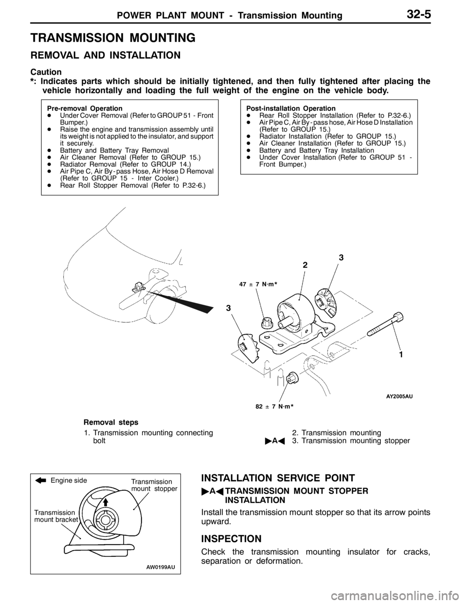
POWER PLANT MOUNT - Transmission Mounting32-5
TRANSMISSION MOUNTING
REMOVAL AND INSTALLATION
Caution
*: Indicates parts which should be initially tightened, and then fully tightened after placing the
vehicle horizontally and loading the full weight of the engine on the vehicle body.
Pre-removal Operation
DUnder Cover Removal (Refer to GROUP 51 - Front
Bumper.)
DRaise the engine and transmission assembly until
its weight is not applied to the insulator, and support
it securely.
DBattery and Battery Tray Removal
DAir Cleaner Removal (Refer to GROUP 15.)
DRadiator Removal (Refer to GROUP 14.)
DAir Pipe C, Air By - pass Hose, Air Hose D Removal
(Refer to GROUP 15 - Inter Cooler.)
DRear Roll Stopper Removal (Refer to P.32-6.)Post-installation Operation
DRear Roll Stopper Installation (Refer to P.32-6.)
DAir Pipe C, Air By - pass hose, Air Hose D Installation
(Refer to GROUP 15.)
DRadiator Installation (Refer to GROUP 15.)
DAir Cleaner Installation (Refer to GROUP 15.)
DBattery and Battery Tray Installation
DUnder Cover Installation (Refer to GROUP 51 -
Front Bumper.)
47±7 N·m*
3
3
82±7 N·m*
2
1
Removal steps
1. Transmission mounting connecting
bolt2. Transmission mounting
"AA3. Transmission mounting stopper
INSTALLATION SERVICE POINT
"AATRANSMISSION MOUNT STOPPER
INSTALLATION
Install the transmission mount stopper so that its arrow points
upward.
INSPECTION
Check the transmission mounting insulator for cracks,
separation or deformation.
Engine side
Transmission
mount bracketTransmission
mount stopper
Page 1071 of 1449

35B-1
ANTI-SKID
BRAKING SYSTEM
(ABS) <4WD>
CONTENTS
GENERAL INFORMATION 2..................
SERVICE SPECIFICATIONS 3.................
LUBRICANTS Refer to GROUP 35A..........
SEALANT Refer to GROUP 35A..............
SPECIAL TOOLS 4...........................
TROUBLESHOOTING 4.......................
ON-VEHICLE SERVICE 26....................
Brake Pedal Check and Adjustment
Refer to GROUP 35A ..........................
Brake Booster Operating Test
Refer to GROUP 35A ..........................
Check Valve Operation Check
Refer to GROUP 35A ..........................
Bleeding Refer to GROUP 35A..................
Brake Fluid Level Sensor Check
Refer to GROUP 35A ..........................
Disc Brake Pad Check and
Replacement Refer to GROUP 35A..............Disc Brake Rotor Check Refer to GROUP 35A...
Brake Disc Thickness Check
Refer to GROUP 35A ..........................
Brake Disc Run-out Check and Correction
Refer to GROUP 35A ..........................
Wheel Speed Sensor Output Voltage Check
26 ............................................
Hydraulic Unit Check 28........................
Remedy for a Flat Battery 29...................
BRAKE PEDAL Refer to GROUP 35A........
MASTER CYLINDER AND BRAKE
BOOSTER Refer to GROUP 35A............
DISC BRAKE Refer to GROUP 35A..........
HYDRAULIC UNIT AND ABS-ECU 30.........
WHEEL SPEED SENSOR 33..................
G SENSORS AND STEERING WHEEL
SENSOR 35..................................
Page 1080 of 1449
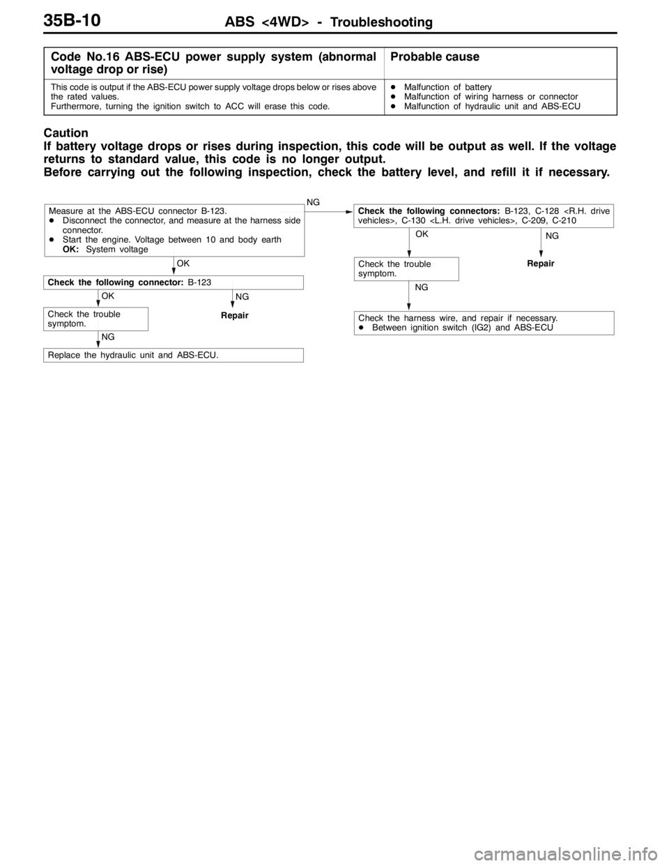
ABS <4WD> -Troubleshooting35B-10
Code No.16 ABS-ECU power supply system (abnormal
voltage drop or rise)Probable cause
This code is output if the ABS-ECU power supply voltage drops below or rises above
the rated values.
Furthermore, turning the ignition switch to ACC will erase this code.DMalfunction of battery
DMalfunction of wiring harness or connector
DMalfunction of hydraulic unit and ABS-ECU
Caution
If battery voltage drops or rises during inspection, this code will be output as well. If the voltage
returns to standard value, this code is no longer output.
Before carrying out the following inspection, check the battery level, and refill it if necessary.
NGNG
Repair
NG
Replace the hydraulic unit and ABS-ECU.
NG
Repair
Check the harness wire, and repair if necessary.
DBetween ignition switch (IG2) and ABS-ECU
OK
Check the trouble
symptom.
OK
Check the trouble
symptom.
OK
Check the following connector:B-123
NGCheck the following connectors:B-123, C-128
DDisconnect the connector, and measure at the harness side
connector.
DStart the engine. Voltage between 10 and body earth
OK:System voltage
Page 1082 of 1449
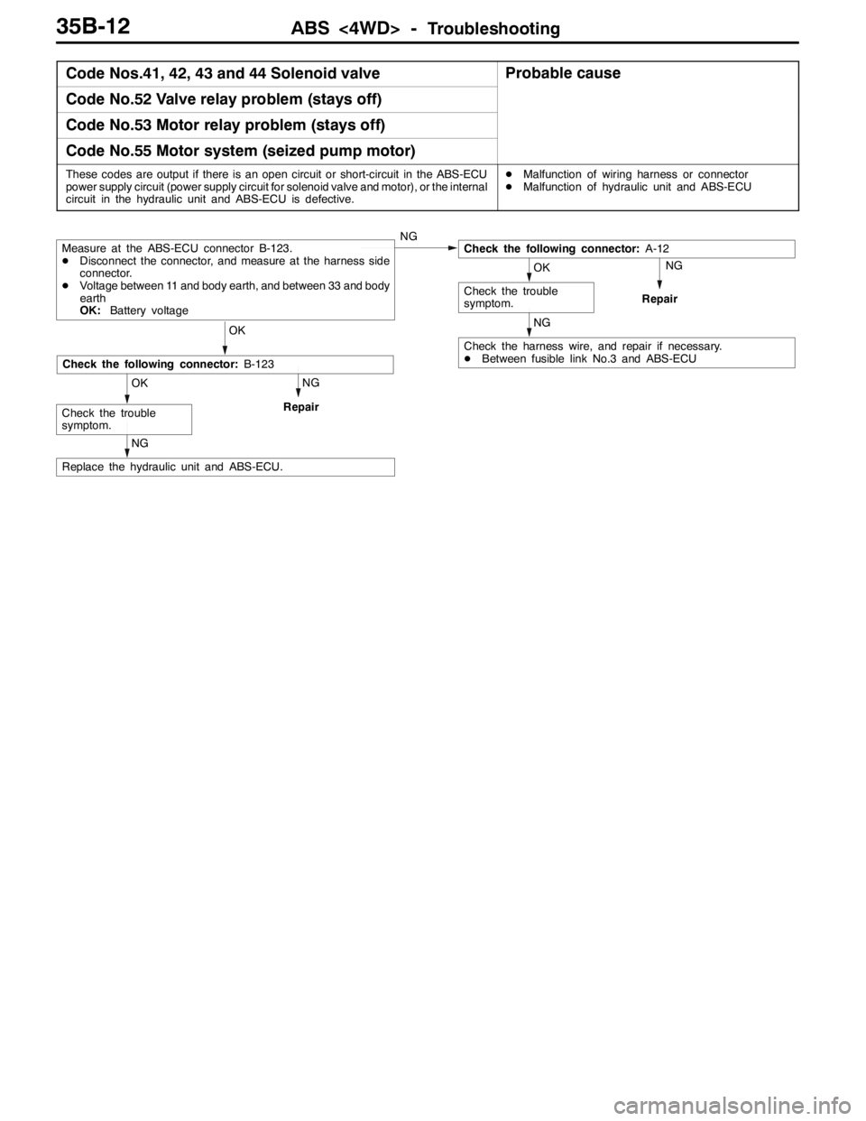
ABS <4WD> -Troubleshooting35B-12
Code Nos.41, 42, 43 and 44 Solenoid valveProbable cause
Code No.52 Valve relay problem (stays off)
Code No.53 Motor relay problem (stays off)
Code No.55 Motor system (seized pump motor)
These codes are output if there is an open circuit or short-circuit in the ABS-ECU
power supply circuit (power supply circuit for solenoid valve and motor), or the internal
circuit in the hydraulic unit and ABS-ECU is defective.DMalfunction of wiring harness or connector
DMalfunction of hydraulic unit and ABS-ECU
NG
Repair
NG
Check the harness wire, and repair if necessary.
DBetween fusible link No.3 and ABS-ECU
NG
Repair
NG
Replace the hydraulic unit and ABS-ECU.
OK
Check the trouble
symptom.
Check the following connector:B-123
OK
OK
Check the trouble
symptom.
Check the following connector:A-12Measure at the ABS-ECU connector B-123.
DDisconnect the connector, and measure at the harness side
connector.
DVoltage between 11 and body earth, and between 33 and body
earth
OK:Battery voltageNG
Page 1090 of 1449
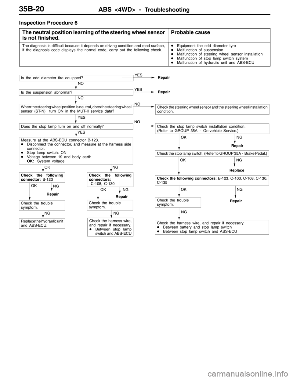
ABS <4WD> -Troubleshooting35B-20
Inspection Procedure 6
The neutral position learning of the steering wheel sensor
is not finished.
Probable cause
The diagnosis is difficult because it depends on driving condition and road surface,
if the diagnosis code displays the normal code, carry out the following check.DEquipment the odd diameter tyre
DMalfunction of suspension
DMalfunction of steering wheel sensor installation
DMalfunction of stop lamp switch system
DMalfunction of hydraulic unit and ABS-ECU
NG
NG
NG
NG
Check the harness wire, and repair if necessary.
DBetween battery and stop lamp switch
DBetween stop lamp switch and ABS-ECU
OK
Check the trouble
symptom.
OK
Check the following connectors:B-123, C-103, C-108, C-130,
C-135
OK
Check the stop lamp switch. (Refer to GROUP 35A - Brake Pedal.)
Check the stop lamp switch installation condition.
(Refer to GROUP 35A - On-vehicle Service.) NO
Repair
OKNG
RepairOKNG
RepairReplace
NG
Replace the hydraulic unit
and ABS-ECU.
NG
Check the harness wire,
and repair if necessary.
DBetween stop lamp
switch and ABS-ECURepair
Check the trouble
symptom.
NG
Check the following
connectors:
C-108, C-130
Check the trouble
symptom.
OK
Check the following
connector:B-123
YES
Measure at the ABS-ECU connector B-123.
DDisconnect the connector, and measure at the harness side
connector.
DStop lamp switch: ON
DVoltage between 19 and body earth
OK:System voltage
Does the stop lamp turn on and off normally?
YES
Repair
NO
Is the odd diameter tire equipped?
YES
Repair
NO
Is the suspension abnormal?
NO
YES
When the steering wheel position is neutral, does the steering wheel
sensor (ST-N) turn ON in the MUT-II service data?Check the steering wheel sensor and the steering wheel installation
condition.
Page 1099 of 1449
ABS <4WD> -On-vehicle Service35B-29
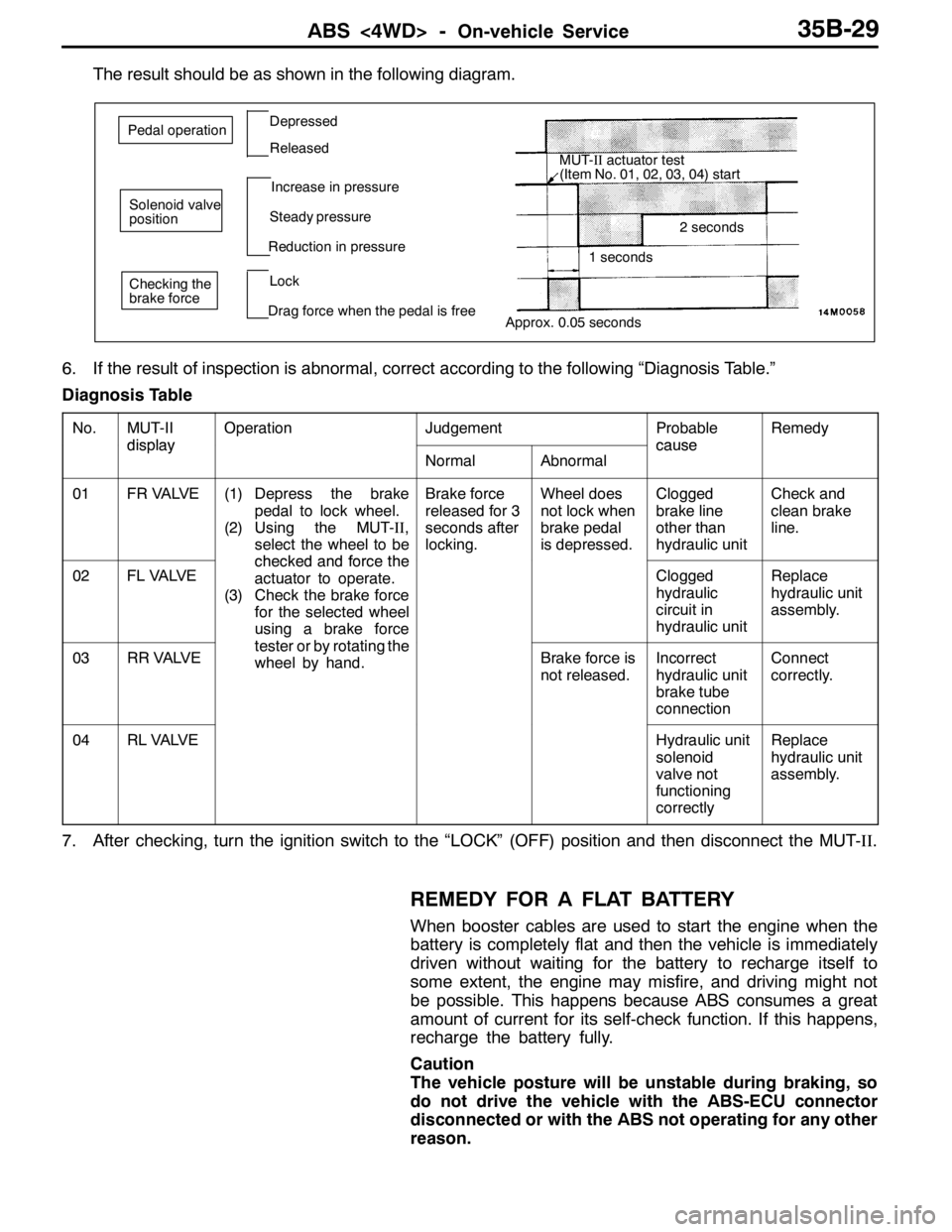
The result should be as shown in the following diagram.
Approx. 0.05 seconds
Pedal operationDepressed
Released
Solenoid valve
positionIncrease in pressure
Steady pressure
Reduction in pressure
Checking the
brake forceLock
Drag force when the pedal is freeMUT-IIactuator test
(Item No. 01, 02, 03, 04) start
2 seconds
1 seconds
6. If the result of inspection is abnormal, correct according to the following “Diagnosis Table.”
Diagnosis Table
No.MUT-II
display
OperationJudgementProbable
cause
Remedy
display
NormalAbnormal
cause
01FR VALVE(1) Depress the brake
pedal to lock wheel.
(2) Using the MUT-II,
select the wheel to be
checkedandforcethe
Brake force
released for 3
seconds after
locking.Wheel does
not lock when
brake pedal
is depressed.Clogged
brake line
other than
hydraulic unitCheck and
clean brake
line.
02FL VALVEchecked and force the
actuator to operate.
(3) Check the brake force
for the selected wheel
using a brake force
ttbttith
Clogged
hydraulic
circuit in
hydraulic unitReplace
hydraulic unit
assembly.
03RR VALVE
g
tester or by rotating the
wheel by hand.Brake force is
not released.Incorrect
hydraulic unit
brake tube
connectionConnect
correctly.
04RL VALVEHydraulic unit
solenoid
valve not
functioning
correctlyReplace
hydraulic unit
assembly.
7. After checking, turn the ignition switch to the “LOCK” (OFF) position and then disconnect the MUT-II.
REMEDY FOR A FLAT BATTERY
When booster cables are used to start the engine when the
battery is completely flat and then the vehicle is immediately
driven without waiting for the battery to recharge itself to
some extent, the engine may misfire, and driving might not
be possible. This happens because ABS consumes a great
amount of current for its self-check function. If this happens,
recharge the battery fully.
Caution
The vehicle posture will be unstable during braking, so
do not drive the vehicle with the ABS-ECU connector
disconnected or with the ABS not operating for any other
reason.