2007 MITSUBISHI LANCER EVOLUTION battery
[x] Cancel search: batteryPage 1182 of 1449
BODY -DoorsBODY -Doors42-34
"BAOPERATION CHECK
1. Install the glass to the window regulator assembly.
Caution
(1) As fully open position which is programed in the
power window-ECU is released (initialized), the
window regulator assembly should not be
operated until it is installed to the glass.
(2) The clamping prevention function does not
operate the first time that the glass is fully closed.
2. Press the power window switch to fully-open the glass,
and then return the glass toward the fully-close position
about 30 mm each. In the fully-close position, keep on
pressing the power window switch for 0.5 second or more.
NOTE
This operation will program the power window-ECU.
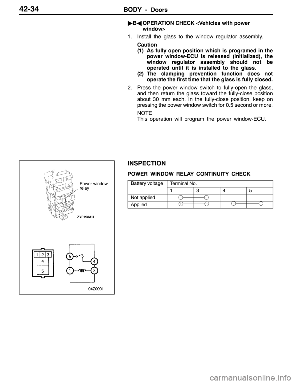
INSPECTION
POWER WINDOW RELAY CONTINUITY CHECK
Battery voltageTerminal No.yg
1345
Not applied
Applied
Power window
relay
123
4
5
Page 1209 of 1449
EXTERIOR -Windshield Wiper and Washer51-17
INSPECTIONS
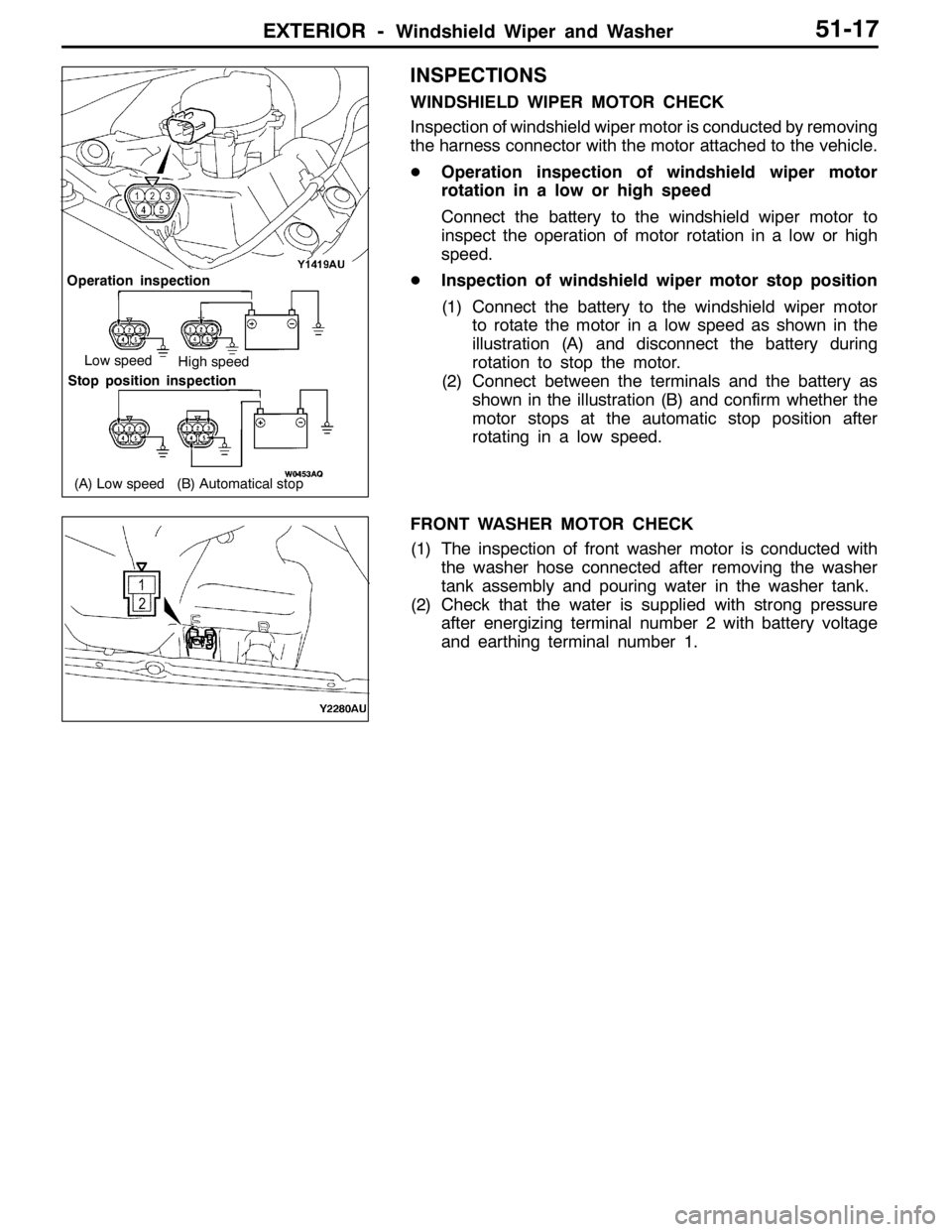
WINDSHIELD WIPER MOTOR CHECK
Inspection of windshield wiper motor is conducted by removing
the harness connector with the motor attached to the vehicle.
DOperation inspection of windshield wiper motor
rotation in a low or high speed
Connect the battery to the windshield wiper motor to
inspect the operation of motor rotation in a low or high
speed.
DInspection of windshield wiper motor stop position
(1) Connect the battery to the windshield wiper motor
to rotate the motor in a low speed as shown in the
illustration (A) and disconnect the battery during
rotation to stop the motor.
(2) Connect between the terminals and the battery as
shown in the illustration (B) and confirm whether the
motor stops at the automatic stop position after
rotating in a low speed.
FRONT WASHER MOTOR CHECK
(1) The inspection of front washer motor is conducted with
the washer hose connected after removing the washer
tank assembly and pouring water in the washer tank.
(2) Check that the water is supplied with strong pressure
after energizing terminal number 2 with battery voltage
and earthing terminal number 1.
(B) Automatical stop
Operation inspection
Low speedHigh speed
Stop position inspection
(A) Low speed
Page 1216 of 1449
EXTERIOR -Outside MirrorEXTERIOR -Outside Mirror51-24
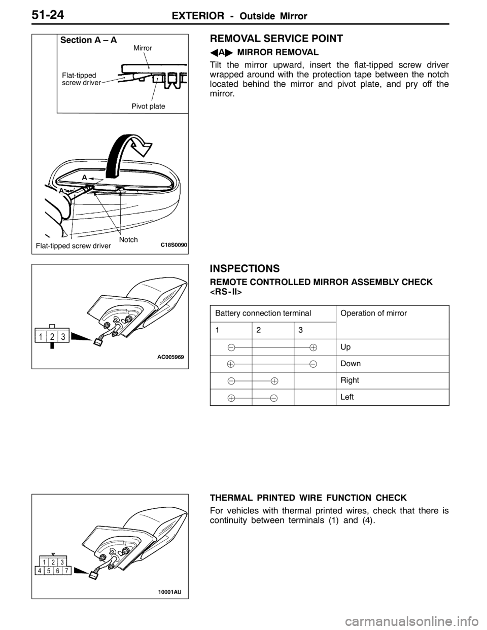
REMOVAL SERVICE POINT
AA"MIRROR REMOVAL
Tilt the mirror upward, insert the flat-tipped screw driver
wrapped around with the protection tape between the notch
located behind the mirror and pivot plate, and pry off the
mirror.
INSPECTIONS
REMOTE CONTROLLED MIRROR ASSEMBLY CHECK
Battery connection terminalOperation of mirror
123
Up
Down
Right
Left
THERMAL PRINTED WIRE FUNCTION CHECK
For vehicles with thermal printed wires, check that there is
continuity between terminals (1) and (4).
Section A – A
Notch Flat-tipped
screw driver
Pivot plate
AMirrorFlat-tipped screw driverA
Page 1247 of 1449

SRS -SRS Service Precautions52B-3
SRS SERVICE PRECAUTIONS
1. In order to avoid injury to yourself or others
from accidental deployment of the air bag and
accidental operation of the seat belt with
pre-tensioner during servicing, read and
carefully follow all the precautions and
procedures described in this manual.
2. Do not use any electrical test equipment on
or near SRS components, except those
specified on P.52B-6.
3. Never Attempt to Repair the Following
Components:
DSRS air bag control unit (SRS-ECU)
DClock spring
DDriver’s and front passenger’s air bag
modules
DSeat belt with pre-tensionerNOTE
If any of these components are diagnosed as
faulty, they should only be replaced, in
accordance with the INDIVIDUAL COM-
PONENTS SERVICE procedures in this
manual. (Refer to P.52B-49.)
4. After disconnecting the negative (–) battery cable,
wait 60 seconds at least before any service and
insulate the disconnected cable with tape. The SRS
retain enough voltage to deploy the air bags for a
short time even after the disconnection of the battery.
So, serious injury may result by accidental air bag
deployment if a work is done on the SRS just after
the disconnection of the battery.
5. Do not attempt to repair the wiring harness connectors
of the SRS. If the connector(s) are diagnosed as defective,
replace the wiring harness(es). If the harness(es) are
diagnosed as faulty, replace or repair the wiring
harness(es) according to the table that follows.
Insulating tape
Battery
SRS-ECU connector
Page 1254 of 1449

SRS -Troubleshooting52B-10
Code no.Page Diagnostic item
34*2Connector lock system52B-29
35SRS-ECU (deployed air bag) system52B-29
41*2Power supply circuit system (fuse No.2 circuit)52B-30
42*2Power supply circuit system (fuse No.3 circuit)52B-32
43*2SRS warning lamp drive circuit systemLamp does not illumi-
nate.52B-33
SRS warning lamp drive circuit systemLamp does not go out.52B-33
44*2SRS warning lamp drive circuit system52B-33
45SRS-EUC internal circuit system including non - volatile memory (EEPROM)52B-11
51Driver’s air bag module (squib) ignition drive circuit systemShort in the ignition
drive circuit52B-11
52Driver’s air bag module (squib) ignition drive circuit systemOpen in the ignition
drive circuit
54Front passenger’s air bag (squib) ignition drive circuit
systemShort in the ignition
drive circuit52B-11
55Front passenger’s air bag (squib) ignition drive circuit
systemOpen in the ignition
drive circuit
56Driver’s seat belt pre-tensioner (squib) ignition drive circuit
systemShort in the ignition
drive circuit52B-11
57Driver’s seat belt pre-tensioner (squib) ignition drive circuit
systemOpen in the ignition
drive circuit
58Front passenger’s seat belt pre-tensioner (squib) ignition
drive circuit systemShort in the ignition
drive circuit52B-11
59Front passenger’s seat belt pre-tensioner (squib) ignition
drive circuit systemOpen in the ignition
drive circuit
61Driver’s air bag module (squib) systemShort-circuited to
power supply52B-34
62Driver’s air bag module (squib) systemShort-circuited to earth
64Front passenger’s air bag module (squib) systemShort-circuited to
power supply52B-38
65Front passenger’s air bag module (squib) systemShort-circuited to earth
66Driver’s seat belt pre-tensioner (squib) systemShort-circuited to
power supply52B-39
67Driver’s seat belt pre-tensioner (squib) systemShort-circuited to earth
68Front passenger’s seat belt pre-tensioner (squib) systemShort-circuited to
power supply52B-40
69Front passenger’s seat belt pre-tensioner (squib) systemShort-circuited to earth
NOTE
(1) *1: If the trouble(s) are removed, the SRS warning lamp go out with diagnosis code history stored.
(2) *2: If the trouble(s) are removed, the SRS warning lamp will go out with diagnosis code history automatically erased.
(3) When the battery has been discharged, diagnosis code No.41 or 42 is stored. Check the battery when either of
these is displayed.
Page 1255 of 1449

SRS -Troubleshooting52B-11
INSPECTION PROCEDURE CLASSIFIED BY DIAGNOSIS CODE
Code No.14, 15, 16, 31, 32, 45, 51, 52, 54, 55, 56, 57, 58, 59
System inside SRS-ECUProbable cause
Malfunction is present inside SRS-ECU. See table below for what each code
tells.DMalfunction of SRS-ECU
Code No.Defective partsTrouble
14Front impact analog G-sensorDNot operating
DAbnormal characteristics
DAbnormal output
15Front impact safing G-sensorDShort in the circuit
16DOpen in the circuit
31DC-DC converterDTerminal voltage of the converter higher than specified for
five seconds or more
32DTerminal voltage of the converter lower than specified for
5 seconds or more (this code is not detected when code
No.41 or 42, which indicates discharged battery, has been
detected)
45Non-volatile memory (EEPROM)DDefective parts inside
51Driver’sairbagmodule(squib)DShortinthecircuit51Driver’sairbag module(squib)
ignitiondrivecircuit
DShortinthecircuit
52ignition drive circuitDOpen in the circuit
54Front passenger’s air bag module
(squib)ignitiondrivecircuit
DShort in the circuit
55(squib)ignitiondrive circuitDOpen in the circuit
56Driver’s seat belt pre-tensioner
(squib)ignitiondrivecircuit
DShort in the circuit
57(squib)ignitiondrive circuitDOpen in the circuit
58Front passenger’s seat belt pre-ten-
sioner(squib)ignitiondrivecircuit
DShort in the circuit
59sioner(squib)ignitiondrive circuitDOpen in the circuit
If the above - mentioned code No. is output, replace the SRS-ECU.
Page 1257 of 1449
SRS -Troubleshooting52B-13
NG
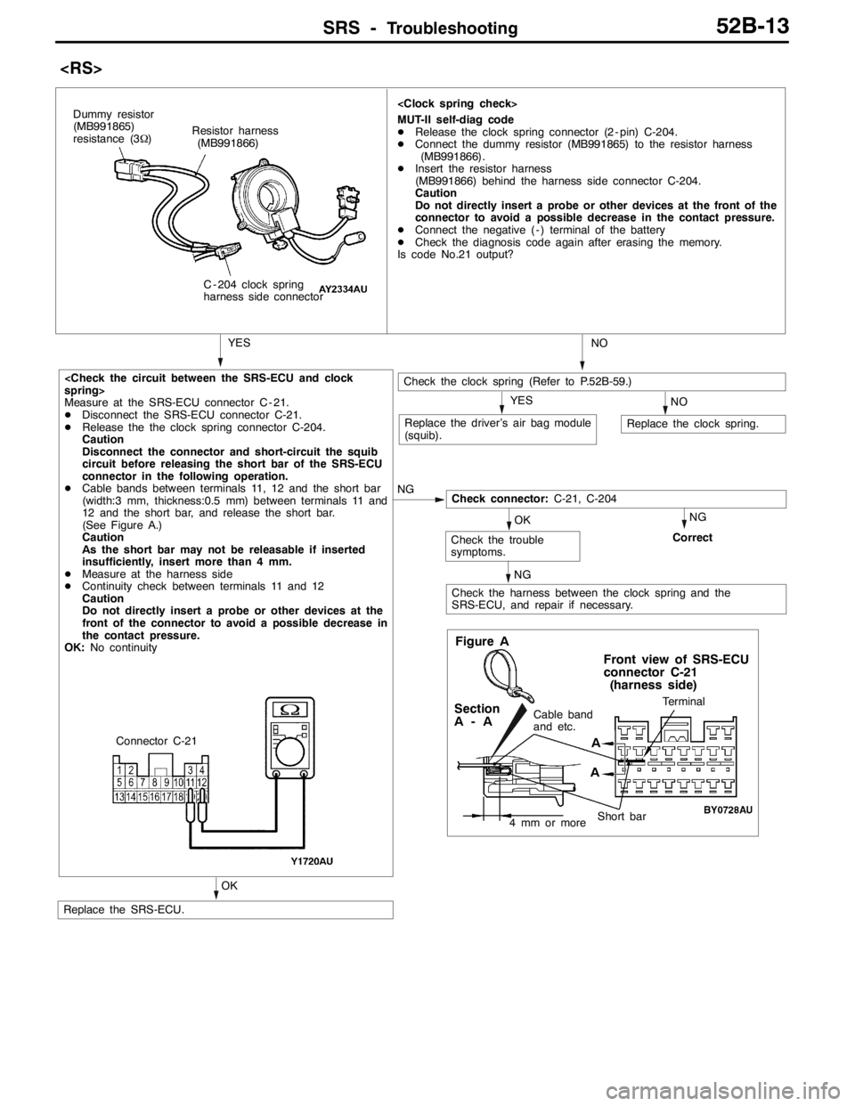
Measure at the SRS-ECU connector C - 21.
DDisconnect the SRS-ECU connector C-21.
DRelease the the clock spring connector C-204.
Caution
Disconnect the connector and short-circuit the squib
circuit before releasing the short bar of the SRS-ECU
connector in the following operation.
DCable bands between terminals 11, 12 and the short bar
(width:3 mm, thickness:0.5 mm) between terminals 11 and
12 and the short bar, and release the short bar.
(See Figure A.)
Caution
As the short bar may not be releasable if inserted
insufficiently, insert more than 4 mm.
DMeasure at the harness side
DContinuity check between terminals 11 and 12
Caution
Do not directly insert a probe or other devices at the
front of the connector to avoid a possible decrease in
the contact pressure.
OK:No continuity
Check connector:C-21, C-204
MUT-II self-diag code
DRelease the clock spring connector (2 - pin) C-204.
DConnect the dummy resistor (MB991865) to the resistor harness
(MB991866).
DInsert the resistor harness
(MB991866) behind the harness side connector C-204.
Caution
Do not directly insert a probe or other devices at the front of the
connector to avoid a possible decrease in the contact pressure.
DConnect the negative ( - ) terminal of the battery
DCheck the diagnosis code again after erasing the memory.
Is code No.21 output?
Resistor harness
(MB991866)
C - 204 clock spring
harness side connector
YES Dummy resistor
(MB991865)
resistance (3Ω)
Check the clock spring (Refer to P.52B-59.)
NOYES
Replace the clock spring.Replace the driver’s air bag module
(squib).NO
Check the harness between the clock spring and the
SRS-ECU, and repair if necessary.
Check the trouble
symptoms.Correct
OK
NG NG
Replace the SRS-ECU.
OK
Figure A
Terminal
Short bar
Front view of SRS-ECU
connector C-21
(harness side)
Cable band
and etc.Section
A-A
4 mm or more
A
AConnector C-21
Page 1258 of 1449
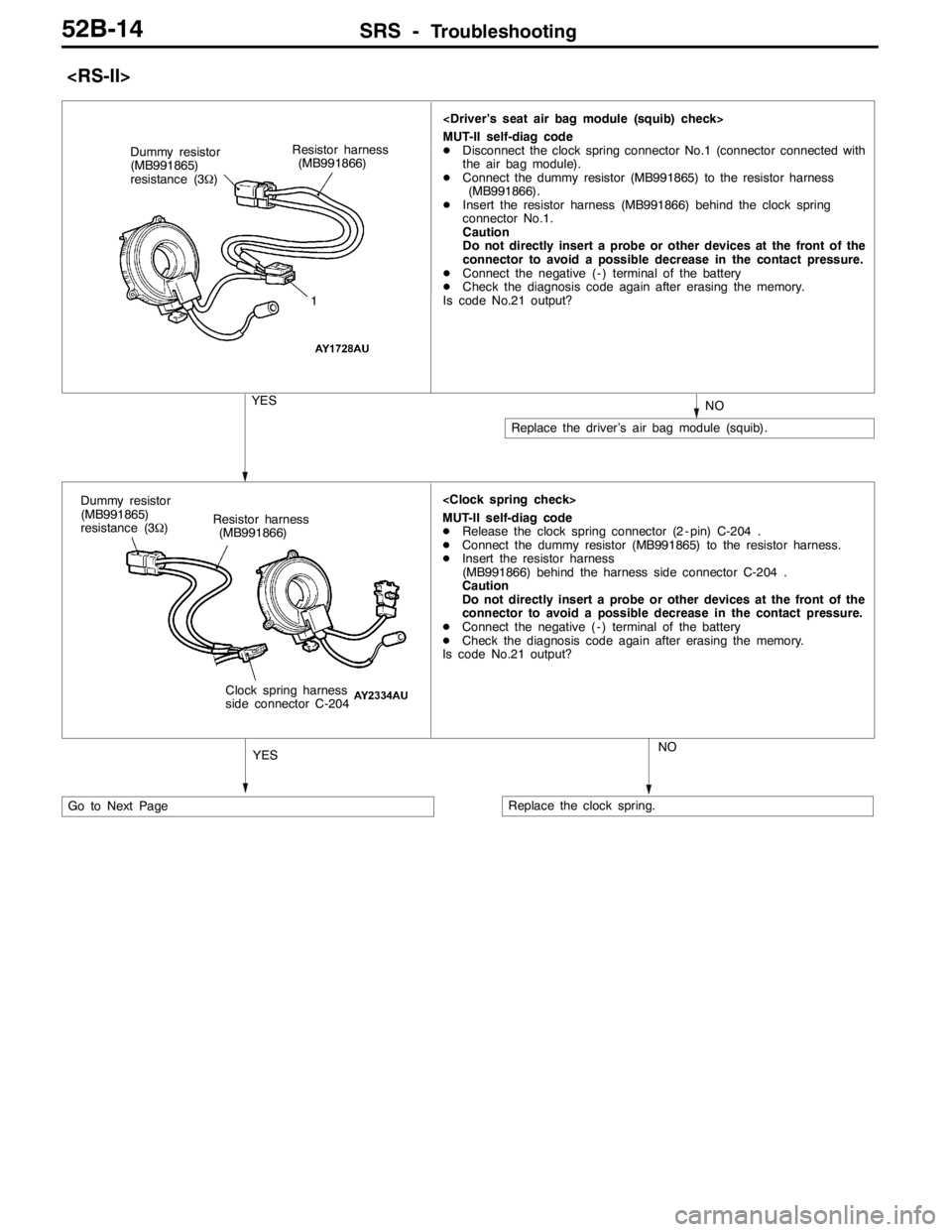
SRS -Troubleshooting52B-14
MUT-II self-diag code
DDisconnect the clock spring connector No.1 (connector connected with
the air bag module).
DConnect the dummy resistor (MB991865) to the resistor harness
(MB991866).
DInsert the resistor harness (MB991866) behind the clock spring
connector No.1.
Caution
Do not directly insert a probe or other devices at the front of the
connector to avoid a possible decrease in the contact pressure.
DConnect the negative ( - ) terminal of the battery
DCheck the diagnosis code again after erasing the memory.
Is code No.21 output? Dummy resistor
(MB991865)
resistance (3Ω)
1
YESNO
Replace the driver’s air bag module (squib). Resistor harness
(MB991866)
Go to Next Page
MUT-II self-diag code
DRelease the clock spring connector (2 - pin) C-204 .
DConnect the dummy resistor (MB991865) to the resistor harness.
DInsert the resistor harness
(MB991866) behind the harness side connector C-204 .
Caution
Do not directly insert a probe or other devices at the front of the
connector to avoid a possible decrease in the contact pressure.
DConnect the negative ( - ) terminal of the battery
DCheck the diagnosis code again after erasing the memory.
Is code No.21 output?
YESNO
Replace the clock spring. Resistor harness
(MB991866)
Clock spring harness
side connector C-204 Dummy resistor
(MB991865)
resistance (3Ω)