Page 786 of 1449
ENGINE AND EMISSION CONTROL -Emission Control System17-16
EGR CONTROL SOLENOID VALVE CHECK
NOTE
When disconnecting the vacuum hose, always make a mark
so that it can be reconnected at original position.
1. Disconnect the vacuum hose (yellow stripe, green stripe,
white stripe) from the solenoid valve.
2. Disconnect the harness connector.
3. Connect a hand vacuum pump to the nipple to which
the green-striped vacuum hose was connected.
4. Check airtightness by applying a vacuum with voltage
applied directly from the battery to the EGR control
solenoid valve and without applying voltage.
Battery voltageB nipple conditionNormal condition
Not appliedOpenVacuum maintained
AppliedOpenVacuum leaks
ClosedVacuum maintained
5. Measure the resistance between the terminals of the
solenoid valve.
Standard value: 29 - 35Ω(at 20_C)
Battery
A B
C
Page 788 of 1449
ENGINE AND EMISSION CONTROL -Emission Control System17-18
CANISTER
REMOVAL AND INSTALLATION
Pre-removal and Post-installation Operation
DAir Pipe C, Air Hose D Removal and Installation (Refer to GROUP 15 - Inter Cooler.)
DBattery and Battery Tray Removal and Installation
DAir Cleaner Assembly Removal and Installation (Refer to GROUP 15 - Air Cleaner.)
1 2
3 4
5
67
89
Canister removal steps
1. Purge hose
2. Check valve
3. Vapor hose
4. Vent connector
5. Vapor hose6. Hose clamp
7. Canister
8. Fuel high pressure hose
9. Canister bracket assembly
Page 816 of 1449

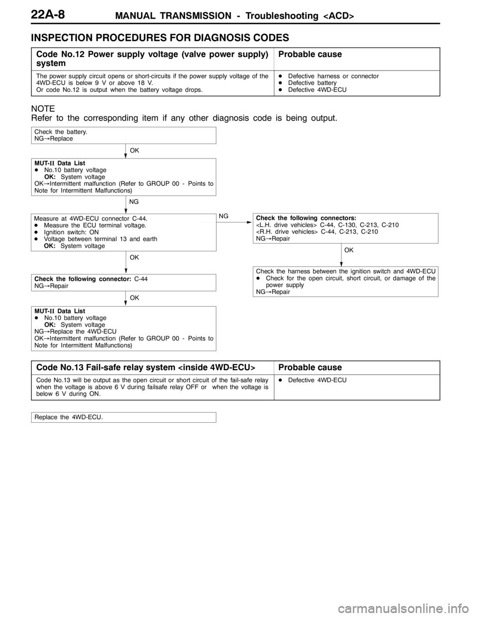
MANUAL TRANSMISSION - Troubleshooting 22A-8
INSPECTION PROCEDURES FOR DIAGNOSIS CODES
Code No.12 Power supply voltage (valve power supply)
systemProbable cause
The power supply circuit opens or short-circuits if the power supply voltage of the
4WD-ECU is below 9 V or above 18 V.
Or code No.12 is output when the battery voltage drops.DDefective harness or connector
DDefective battery
DDefective 4WD-ECU
NOTE
Refer to the corresponding item if any other diagnosis code is being output.
OKOK
NG
NG
OK
Check the battery.
NG→Replace
Measure at 4WD-ECU connector C-44.
DMeasure the ECU terminal voltage.
DIgnition switch: ON
DVoltage between terminal 13 and earth
OK:System voltageCheck the following connectors:
C-44, C-130, C-213, C-210
C-44, C-213, C-210
NG→Repair
MUT-IIData List
DNo.10 battery voltage
OK:System voltage
OK→Intermittent malfunction (Refer to GROUP 00 - Points to
Note for Intermittent Malfunctions)
OK
Check the following connector:C-44
NG→Repair
MUT-IIData List
DNo.10 battery voltage
OK:System voltage
NG→Replace the 4WD-ECU
OK→Intermittent malfunction (Refer to GROUP 00 - Points to
Note for Intermittent Malfunctions)
Check the harness between the ignition switch and 4WD-ECU
DCheck for the open circuit, short circuit, or damage of the
power supply
NG→Repair
Code No.13 Fail-safe relay system Probable cause
Code No.13 will be output as the open circuit or short circuit of the fail-safe relay
when the voltage is above 6 V during failsafe relay OFF or when the voltage is
below 6 V during ON.DDefective 4WD-ECU
Replace the 4WD-ECU.
Page 833 of 1449

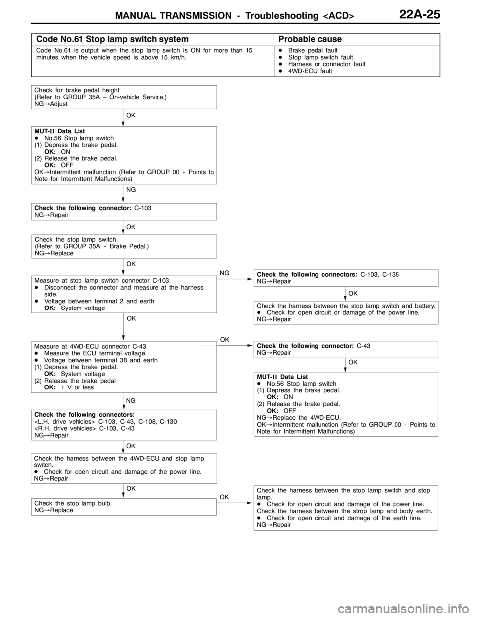
MANUAL TRANSMISSION - Troubleshooting 22A-25
Code No.61 Stop lamp switch systemProbable cause
Code No.61 is output when the stop lamp switch is ON for more than 15
minutes when the vehicle speed is above 15 km/h.DBrake pedal fault
DStop lamp switch fault
DHarness or connector fault
D4WD-ECU fault
OK
OK
OK
NG
OK
Check for brake pedal height
(Refer to GROUP 35A – On-vehicle Service.)
NG→Adjust
NG
MUT-IIData List
DNo.56 Stop lamp switch
(1) Depress the brake pedal.
OK:ON
(2) Release the brake pedal.
OK:OFF
OK→Intermittent malfunction (Refer to GROUP 00 - Points to
Note for Intermittent Malfunctions)
OK
Check the following connector:C-103
NG→Repair
Check the stop lamp switch.
(Refer to GROUP 35A - Brake Pedal.)
NG→Replace
NG
OK
Check the following connectors:C-103, C-135
NG→Repair
Check the harness between the stop lamp switch and battery.
DCheck for open circuit or damage of the power line.
NG→Repair
OK
Measure at stop lamp switch connector C-103.
DDisconnect the connector and measure at the harness
side.
DVoltage between terminal 2 and earth
OK:System voltage
Measure at 4WD-ECU connector C-43.
DMeasure the ECU terminal voltage.
DVoltage between terminal 38 and earth
(1) Depress the brake pedal.
OK:System voltage
(2) Release the brake pedal
OK:1 V or less
OK
Check the following connectors:
C-103, C-43, C-108, C-130
C-103, C-43
NG→Repair
OKCheck the harness between the stop lamp switch and stop
lamp.
DCheck for open circuit and damage of the power line.
Check the harness between the strop lamp and body earth.
DCheck for open circuit and damage of the earth line.
NG→Repair
Check the harness between the 4WD-ECU and stop lamp
switch.
DCheck for open circuit and damage of the power line.
NG→Repair
Check the following connector:C-43
NG→Repair
MUT-IIData List
DNo.56 Stop lamp switch
(1) Depress the brake pedal.
OK:ON
(2) Release the brake pedal.
OK:OFF
NG→Replace the 4WD-ECU.
OK→Intermittent malfunction (Refer to GROUP 00 - Points to
Note for Intermittent Malfunctions)
OK
Check the stop lamp bulb.
NG→Replace
Page 843 of 1449

MANUAL TRANSMISSION - Troubleshooting 22A-35
DATA LIST REFERENCE TABLE
Item
no.Check itemCheck conditionNormal conditions
01Wheel speed sensor
Execute actual driving.The speed meter dis-
play and MUT-IIdis-
lth02Wheel speed sensor
py
play match.
03Wheel speed sensor
04Wheel speed sensor
05Wheel speed sensor
(0.2 km/h)
06Wheel speed sensor
(0.2 km/h)
07Wheel speed sensor
(0.2 km/h)
08Wheel speed sensor
(0.2 km/h)
09Vehicle speed
10Battery voltageIgnition switch: ONSystem voltage
11Proportional valve cur-
rent During ACD operation50 - 1,000 mA
12Proportional valve cur-
rent During AYC operation50 - 1,000 mA
13TPS voltageIgnition switch: ON
Engine: StoppedAccelerator pedal: Full
closed535 - 735 mV
Engine:Stopped
Accelerator pedal: PressGradually rises from
the above value
Accelerator pedal: Full
throttle4,500 - 5,000 mV
14Longitudinal G sensor
voltageIgnition switch: ONVehicle stopped (horizon-
tal) state2.4 - 2.6 V
g
Actual drivingThe displayed value
increases and de-
creases mainly around
2.5 V.
15Lateral G sensor volt-
ageIgnition switch: ONVehicle stopped (horizon-
tal) state2.4 - 2.6 V
g
Perform actual drivingThe displayed value
increases and de-
creases mainly around
2.5 V.
16Steering operation
angleIgnition switch: ONSteering wheel: Steer by 90
degrees to the rightR90 deg
g
Steering wheel: Steer by 90
degrees to the leftL90 deg
17Steering angle velocityIgnition switch: ONSteering wheel: No steering0 deg/sggyg
Steering wheel: SteerThe display changes
according to the revolu-
tion speed.
18Pressure sensorDuring electric pump motor operations1.0 - 1.6 MPa
Page 854 of 1449

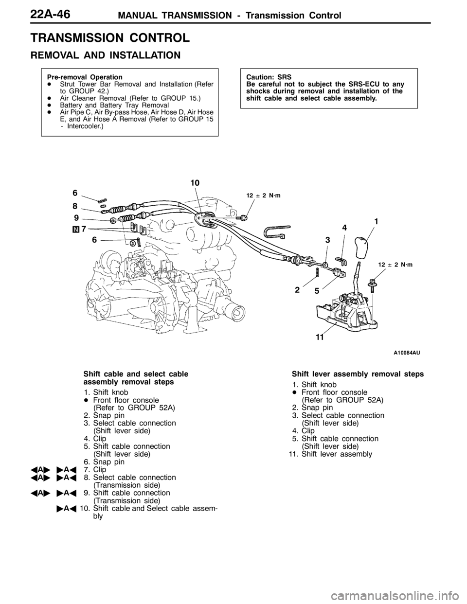
MANUAL TRANSMISSION - Transmission Control22A-46
TRANSMISSION CONTROL
REMOVAL AND INSTALLATION
Pre-removal Operation
DStrut Tower Bar Removal and Installation (Refer
to GROUP 42.)
DAir Cleaner Removal (Refer to GROUP 15.)
DBattery and Battery Tray Removal
DAir Pipe C, Air By-pass Hose, Air Hose D, Air Hose
E, and Air Hose A Removal (Refer to GROUP 15
- Intercooler.)Caution: SRS
Be careful not to subject the SRS-ECU to any
shocks during removal and installation of the
shift cable and select cable assembly.
12±2 N·m
34
21
5 6
7 8
6 910
12±2 N·m
11
Shift cable and select cable
assembly removal steps
1. Shift knob
DFront floor console
(Refer to GROUP 52A)
2. Snap pin
3. Select cable connection
(Shift lever side)
4. Clip
5. Shift cable connection
(Shift lever side)
6. Snap pin
AA""AA7. Clip
AA""AA8. Select cable connection
(Transmission side)
AA""AA9. Shift cable connection
(Transmission side)
"AA10. Shift cable and Select cable assem-
blyShift lever assembly removal steps
1. Shift knob
DFront floor console
(Refer to GROUP 52A)
2. Snap pin
3. Select cable connection
(Shift lever side)
4. Clip
5. Shift cable connection
(Shift lever side)
11. Shift lever assembly
Page 857 of 1449

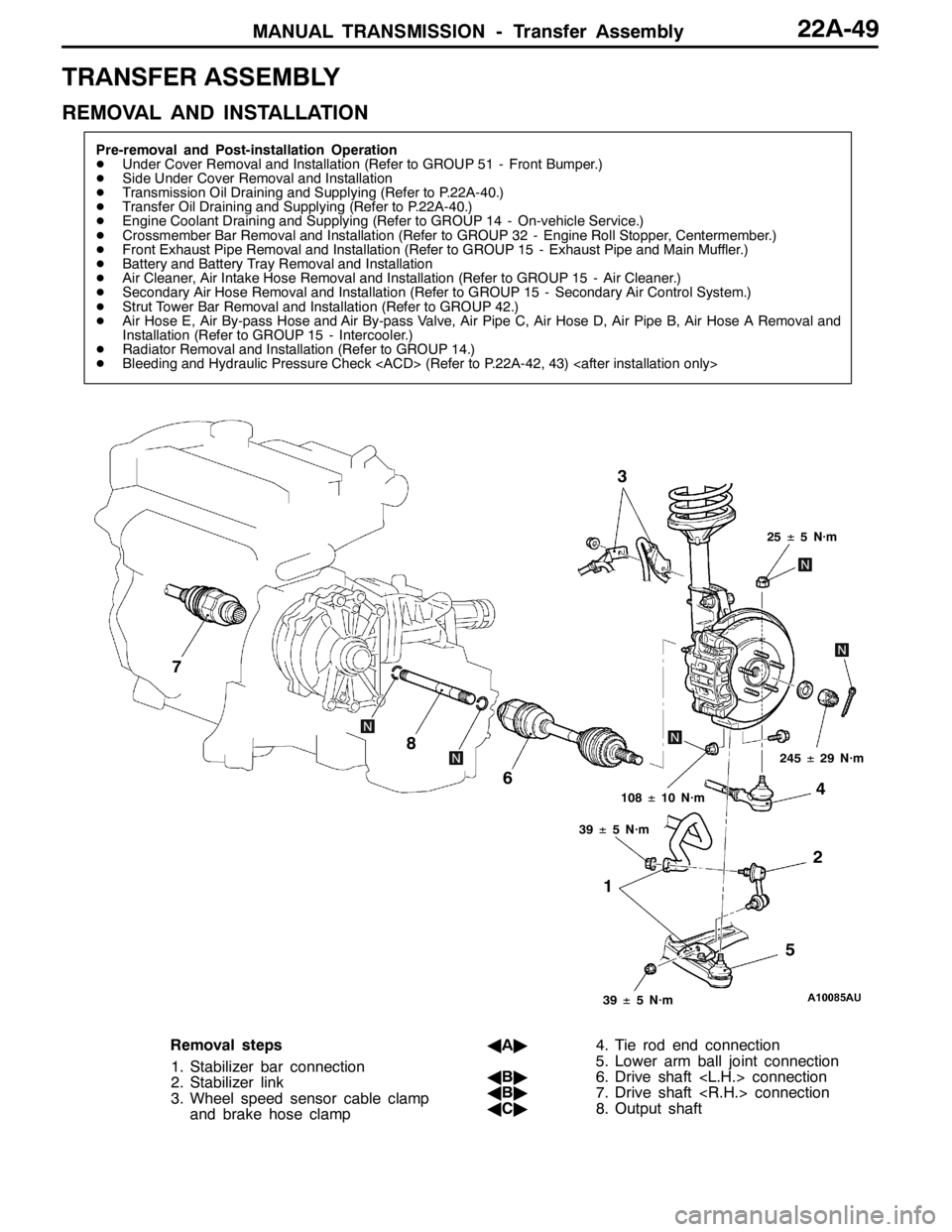
MANUAL TRANSMISSION - Transfer Assembly22A-49
TRANSFER ASSEMBLY
REMOVAL AND INSTALLATION
Pre-removal and Post-installation Operation
DUnder Cover Removal and Installation (Refer to GROUP 51 - Front Bumper.)
DSide Under Cover Removal and Installation
DTransmission Oil Draining and Supplying (Refer to P.22A-40.)
DTransfer Oil Draining and Supplying (Refer to P.22A-40.)
DEngine Coolant Draining and Supplying (Refer to GROUP 14 - On-vehicle Service.)
DCrossmember Bar Removal and Installation (Refer to GROUP 32 - Engine Roll Stopper, Centermember.)
DFront Exhaust Pipe Removal and Installation (Refer to GROUP 15 - Exhaust Pipe and Main Muffler.)
DBattery and Battery Tray Removal and Installation
DAir Cleaner, Air Intake Hose Removal and Installation (Refer to GROUP 15 - Air Cleaner.)
DSecondary Air Hose Removal and Installation (Refer to GROUP 15 - Secondary Air Control System.)
DStrut Tower Bar Removal and Installation (Refer to GROUP 42.)
DAir Hose E, Air By-pass Hose and Air By-pass Valve, Air Pipe C, Air Hose D, Air Pipe B, Air Hose A Removal and
Installation (Refer to GROUP 15 - Intercooler.)
DRadiator Removal and Installation (Refer to GROUP 14.)
DBleeding and Hydraulic Pressure Check (Refer to P.22A-42, 43)
12 3
4
5 6 7
8
25±5 N·m
108±10 N·m
39±5 N·m
39±5 N·m
245±29 N·m
Removal steps
1. Stabilizer bar connection
2. Stabilizer link
3. Wheel speed sensor cable clamp
and brake hose clampAA"4. Tie rod end connection
5. Lower arm ball joint connection
AB"6. Drive shaft connection
AB"7. Drive shaft connection
AC"8. Output shaft
Page 865 of 1449
MANUAL TRANSMISSION -Sensor,SwitchandRelay
vehicles with ACD and AYC>22A-57
INSPECTION
ELECTRIC PUMP RELAY CONTINUITY CHECK
1. Using a jumper wire, connect a battery (+) to terminal
13 of the electric pump relay and battery ( - ) to terminal
1.
2. While intermittently disconnecting the jumper wire at the
battery side, check for continuity between terminals 4
and 5 of the electric pump relay.
Jumper wireContinuity between No.4 - No.5
ConnectedContinuity
DisconnectedNo continuity
ACD MODE SWITCH CONTINUITY CHECK
ACD mode switch
terminalACD mode switchContinuity
No.1 - No.2ONContinuity
OFFNo continuity
No.3 - No.4-Continuity