2007 MITSUBISHI LANCER EVOLUTION battery
[x] Cancel search: batteryPage 178 of 1449

CIRCUIT DIAGRAMSB-80
STARTING SYSTEM (See P.B-79.)
OPERATION
When the ignition switch is turned to the ST position,
the starter contacts (magnet switch) turns ON and
the starter motor starts turning over.TROUBLESHOOTING HINTS
1. Starter motor does not turn over at all.
DCheck starter (coil).
DCheck battery terminals for proper contact.
2. Starter motor does not stop rotating.
DCheck starter (magnet switch).
Page 183 of 1449

CIRCUIT DIAGRAMSB-85
CHARGING SYSTEM (See P.B-84.)
OPERATION
When engine is stationary
DWhen the ignition switch is turned to the ON
position, current flows the alternator L terminal
and, at the same time, the charge warning lamp
illuminates.
When engine is started and after engine has
started
DWhen the engine is started, the charge warning
lamp goes out because of the charging voltage
begin applied to the alternator L terminal.
DThe battery voltage being applied to the
alternator S terminal is monitored by the voltage
regulator. Therefore, the amount of electricity
produced by the alternator is controlled by
allowing and cutting off the current flowing to
the field coil.
DThe alternator B terminal supplies power to
each load.TROUBLESHOOTING HINTS
1. Charging indicator lamp does not illuminate
when the ignition switch is turned to ON
position, before the engine starts.
DCheck multi-purpose fuse No.(2).
DCheck the bulb.
2. Charging indicator lamp fails to switch off once
the engine starts.
DCheck voltage regulator of alternator.
3. Discharged or overcharged battery.
DCheck voltage regulator of alternator.
4. Charge warning lamp illuminates dimly.
DCheck combination meter diode (for short).
Page 358 of 1449

INDEX - In order of connector No.C-2
Wiring diagram
page Circuit diagram page Parts name Connector
No.
AA-45Condenser fan motorB-177,183B-7,9
A-46Condenser fan motorB-177,183B-7,9
A-47A/C compressorB-178,184B-7,9
A-48Power steering oil pressure switchB-90,98B-7,9
BB-01Windshield wiper motorB-186,190B-10,14
B-02Throttle position sensorB-89,97,215,223,231,241B-10,14
B-03Vehicle speed sensorB-92,100,150,154,197B-10,14
B-04Brake fluid level switchB-157B-10,14
B-05XEngine speed detection connectorB-73,82,83,90,98B-10,14
B-06XNo connectionB-73B-10,14
B-07XNo connectionB-73B-10,14
B-08XNo connectionB-73B-10,14
B-09XIgnition coil relay
connection
B-10XNo connectionB-73B-10,14
B-11XEngine control relayB-73,86,94,252,254B-10,14
B-12XA/C compressor relayB-73,178,184B-10,14
B-14Control wiring harness and battery
wiring harness combinationB-79,84,91,99,157B-10,14
B-18StarterB-79B-11,15
B-19StarterB-79B-11,15
B-20Oil pressure switchB-157B-11,15
B-21AlternatorB-84B-11,15
B-22AlternatorB-84B-11,15
B-23Purge control solenoid valveB-91,99B-11,15
B-24Injector 4B-89,97B-11,15
B-25Injector 3B-89,97B-11,15
B-26Injector 2B-89,97B-11,15
B-27Injector 1B-89,97B-11,15
B-31Air flow sensorB-90,98B-11,15
B-34Oxygen sensorB-88,96B-11,15
B-36Waste gate solenoid valveB-91,99B-11,15
B-37Fuel pressure solenoid valveB-90,98B-11,15
Page 368 of 1449

INDEX - In order of parts nameC-12
Wiring diagram
page Circuit diagram page Connector
No. Parts name
CColumn switchC-203B-104,107,112,116,125,128,137,141,
187,191B-22,28
Combination meterC-01B-84,87,95,103,106,118,122,126,129,
135,139,148,149,152,153,156,157,
198,206,214,222,230,240,248,250,
256, 258B-18,24
Combination meterC-02B-110,115,118,122,126,129,135,139,
148,149,152,153,156,157,198,206,
248, 250,256,258B-18,24
Condenser fan motorA-45B-177,183B-7,9
Condenser fan motorA-46B-177,183B-7,9
Condenser fan relay (HI)A-07XB-73,177,183B-6,8
Condenser fan relay (LO)A-06XB-73,177,183B-6,8
Control wiring harness and battery
wiring harness combinationB-14B-79,84,91,99,157B-10,14
Control wiring harness and floor wiring
harness (LH) combination
Crank angle sensorB-121B-88,96B-13,16
DDefogger (-)F-06B-185B-38,39
Defogger (+)F-19B-185B-38,39
Defogger relayC-214B-54,55,78,185B-23,29
Detonation sensorB-122B-89,97B-13,17
Diagnosis connectorC-22B-92,100,105,108,113,117,119,123,
125,128,137,141,150,154,158,164,
170,172,188,189,204,205,219,227,
237,247,248,250,252,254B-18,24
Diagnosis connectorC-23B-92,100B-18,24
Direction valve (LH)
Direction valve (RH)
Door lock actuator (Front:LH)E-08B-170,173B-34,36
Door lock actuator (Front:RH)E-18B-171,172B-35,37
Door lock actuator (Rear:LH)E-12B-171,173B-34,36
Door lock actuator (Rear:RH)E-23B-171,173B-35,37
Door lock key cylinder switch (LH)E-17B-172B-37
Door lock key cylinder switch (RH)E-16B-170B-35
Door switch (Front:LH)D-13B-105,112,120,121,158B-30,32
Door switch (Front:RH)D-01B-108,116,120,121,164B-30,32
Page 383 of 1449

GENERAL -How to Use This Manual00-5
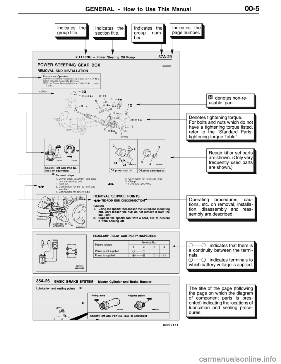
Denotes tightening torque.
For bolts and nuts which do not
have a tightening torque listed,
refer to the “Standard Parts-
tightening-torque Table”.
indicates that there is
a continuity between the termi-
nals.
indicates terminals to
which battery voltage is applied.
Indicates the
section title.Indicates the
group num-
ber.Indicates the
page number.Indicates the
group title.
denotes non-re-
usable part.
Repair kit or set parts
are shown. (Only very
frequently used parts
are shown.)
Operating procedures, cau-
tions, etc. on removal, installa-
tion, disassembly and reas-
sembly are described.
The title of the page (following
the page on which the diagram
of component parts is pres-
ented) indicating the locations of
lubrication and sealing proce-
dures.
Page 386 of 1449

GENERAL -How to Use Troubleshooting/Inspection Service Points00-8
WHEN USING THE WARNING LAMP
1. Use the special tool to earth No.1 terminal (diagnosis
control terminal) of the diagnosis connector.
2. Turn the ignition switch to “ON” position.
3. Read out a diagnosis code by observing how the warning
lamp flashes.
Applicable systems
System nameWarning lamp name
ACD, AYCACD mode indicator lamp
ABSABS warning lamp
Indication of diagnosis code by warning lamp
When the diagnosis code No.24 is outputWhen no diagnosis code is output*
On
Off
1.5 secs.0.5 sec.
0.5 sec.
Pause
time 3
secs.Tens
signalPlace
division
2 secs.Units
signal
On
Off
0.25 sec.
METHOD OF ERASING DIAGNOSIS CODES
WHEN USING THE MUT-II
Connect the MUT-IIto the diagnosis connector and erase the diagnosis code.
Caution
Turn the ignition switch to “LOCK”(OFF) position before connecting or disconnecting the MUT-II.
WHEN NOT USING THE MUT-II
1. Turn the ignition switch to “LOCK”(OFF) position.
2. After disconnecting the battery cable from the battery ( - ) terminal for 10 seconds or more, reconnect
the cable.
3. After the engine has warmed up, run it at idle for about 15 minutes.
MB991529
Page 391 of 1449

GENERAL -How to Use Troubleshooting/Inspection Service Points00-13
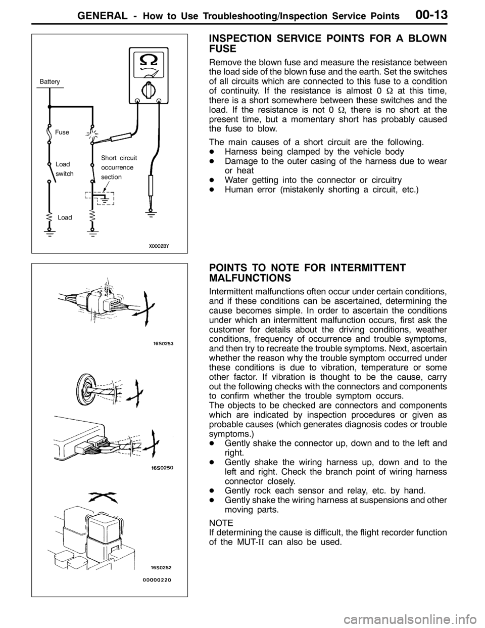
INSPECTION SERVICE POINTS FOR A BLOWN
FUSE
Remove the blown fuse and measure the resistance between
the load side of the blown fuse and the earth. Set the switches
of all circuits which are connected to this fuse to a condition
of continuity. If the resistance is almost 0Ωat this time,
there is a short somewhere between these switches and the
load. If the resistance is not 0Ω, there is no short at the
present time, but a momentary short has probably caused
the fuse to blow.
The main causes of a short circuit are the following.
DHarness being clamped by the vehicle body
DDamage to the outer casing of the harness due to wear
or heat
DWater getting into the connector or circuitry
DHuman error (mistakenly shorting a circuit, etc.)
POINTS TO NOTE FOR INTERMITTENT
MALFUNCTIONS
Intermittent malfunctions often occur under certain conditions,
and if these conditions can be ascertained, determining the
cause becomes simple. In order to ascertain the conditions
under which an intermittent malfunction occurs, first ask the
customer for details about the driving conditions, weather
conditions, frequency of occurrence and trouble symptoms,
and then try to recreate the trouble symptoms. Next, ascertain
whether the reason why the trouble symptom occurred under
these conditions is due to vibration, temperature or some
other factor. If vibration is thought to be the cause, carry
out the following checks with the connectors and components
to confirm whether the trouble symptom occurs.
The objects to be checked are connectors and components
which are indicated by inspection procedures or given as
probable causes (which generates diagnosis codes or trouble
symptoms.)
DGently shake the connector up, down and to the left and
right.
DGently shake the wiring harness up, down and to the
left and right. Check the branch point of wiring harness
connector closely.
DGently rock each sensor and relay, etc. by hand.
DGently shake the wiring harness at suspensions and other
moving parts.
NOTE
If determining the cause is difficult, the flight recorder function
of the MUT-IIcan also be used.
Fuse
Battery
Load
switch
Load
Short circuit
occurrence
section
Page 396 of 1449

GENERAL -Precautions Before Service00-18
PRECAUTIONS BEFORE SERVICE
SUPPLEMENTAL RESTRAINT SYSTEM (SRS)
1. Items to follow when servicing SRS
(1) Be sure to read GROUP 52B - Supplemental Restraint System (SRS).
For safe operations, please follow the directions and heed all warnings.
(2) Wait at least 60 seconds after disconnecting the battery cable before doing any further work.
The SRS system is designed to retain enough voltage to deploy the air bag even after the battery
has been disconnected. Serious injury may result from unintended air bag deployment if work
is done on the SRS system immediately after the battery cable is disconnected.
(3) Warning labels must be heeded when servicing or handling SRS components. Warning labels
are located in the following locations.
DSun visor
DGlove box
DSRS-ECU
DSteering wheel
DSteering Joint Cover
DAir bag module (driver’s side and front passenger’s side)
DClock spring
DSeat belt with pre-tensioner
(4) Always use the designated special tools and test equipment.
(5) Store components removed from the SRS in a clean and dry place.
The air bag module should be stored on a flat surface and placed so that the pad surface is
facing upward.
Do not place anything on top of it.
(6) Never attempt to disassemble or repair the SRS components (SRS-ECU, air bag module, clock
spring and seat belt with pre-tensioner).
(7) Whenever you finish servicing the SRS, check the SRS warning lamp operation to make sure
that the system functions properly.
(8) Be sure to deploy the air bag before disposing of the air bag module or disposing of a vehicle
equipped with an air bag. (Refer to GROUP 52B - Air Bag Module Disposal Procedures.)
2. Observe the following when carrying out operations on places where SRS components are installed,
including operations not directly related to the SRS air bag.
(1) When removing or installing parts do not allow any impact or shock to the SRS components.
(2) SRS components should not be subjected to heat, so remove the SRS components before drying
or baking the vehicle after painting.
DSRS-ECU, air bag module, clock spring: 93_C or more
DSeat belt with pre-tensioner: 90_C or more
After re-installing them, check the SRS warning lamp operation to make sure that the system
functions properly.