Page 1172 of 1449
BODY -Doors42-24
DOOR INSIDE HANDLE LOOSENESS CHECK
AND ADJUSTMENT
1. Check that the door inside handle looseness satisfies
the standard value.
Standard value (A):
Front 9.6±9.2 mm
Rear 9.0±9.2 mm
2. If outside the standard value, remove the door trim.(Refer
to P.42-27.)
3. Adjust the looseness of the inside handle using the clip
joining the inside handle and rod.
A
Section B - B
B
B
Page 1173 of 1449
BODY -Doors42-25
DOOR ASSEMBLY
REMOVAL AND INSTALLATION
Post-installation Operation
Door Adjustment (Refer to P.42-20.)
7
61 2
3 4
5
98
5
2
38
9
67
4
5, 6
21±4 N·m11±2 N·m
11±2 N·m 1.5±0.5 N·m
1.5±0.5 N·m 27±5 N·m
21±4 N·m
1
1 10
10
11±2 N·m
11±2 N·m
21±4 N·m27±5 N·m
27±5 N·m 21±4 N·m 27±5 N·m
1. Damper mail
Door assembly removal steps
2. Harness connector
3. Door check connecting bolt
4. Door assembly
5. Door upper hinge
6. Door lower hingeStriker removal steps
"AA7. Striker
8. Striker shim
Door switch removal
9. Door switch cap
10. Door switch
Page 1175 of 1449
BODY -Doors42-27
DOOR TRIM AND WATERPROOF FILM
REMOVAL AND INSTALLATION
7
91
1011
6 9
9
3
521
2
4 8
4 87 6 5 11
103
Sealant: 3M ATD Part No. 8625 or equivalent
Removal steps
1. Cap
2. Door pull handle
3. Power window switch panel
assembly
AA"4. Door inside handle cover
AB""BA5. Clip
windows>"BA6. Escutcheon
power windows>
"BA7. Regulator handle
power windows>
8. Door trim assembly
9. Speaker
10. Power window switch bracket
"AA11. Waterproof film
Page 1177 of 1449
BODY -Doors42-29
B Note
Section A - A View AView B Claws positions Clips positions
Rear door trimView AView B
Door panelDoor trim Clip
D
Cap View C
D
Section C - C
Cap
ClawPull handle box
View C
B
AW0461AU
AW0772AQ
BW0465AU
Section D - D Section B - B
Door trim
Clip C
C
CC
C
C
A
A
C
C B
B Power window switch
panel assembly
Power window switch
panel assembly
ClawDoor trim Power window switch panel assembly
AW0465AU
Page 1179 of 1449
BODY -Doors42-31
INSTALLATION SERVICE POINTS
"AAWATERPROOF FILM INSTALLATION
Apply the specified adhesive on the waterproof film as shown
in the illustration, and then glue it on the door window glass.
Specified sealant: 3M ATD Part No. 8625 or equivalent
"BAREGULATOR HANDLE/ESCUTCHEON/CLIP
INSTALLATION
1. Install the clip and escutcheon to the regulator handle.
2. Close the front door window glass fully, and then install
the regulator handle as shown in the illustration.
INSPECTION
Power window main switch uses SWS system, for the
power window main switch check, refer to GROUP 54B
- SWS.
POWER WINDOW SUB SWITCH CONTINUITY CHECK
Switch positionTerminal No.p
236
UP
DOWN
Waterproof film
Waterproof film
Front of vehicle
30_
Horizontal line
Page 1180 of 1449
BODY -Doors42-32
DOOR GLASS AND REGULATOR
REMOVAL AND INSTALLATION
Pre-removal Operation
Door Trim and Waterproof Film Removal (Refer to
P.42-27.)Post-installation Operation
DDoor Window Glass Adjustment (Refer to P.42-21.)
DDoor Trim and Waterproof Film Installation (Refer
to P.42-27)
1
23
1
34
25 6
1 1
power windows>
power windows>
Window regulator assembly
removal steps
"BADOperation check
power window>
AA""AA1. Window regulator assembly
AA""AA2. Power window motor assembly
Window glass removal steps
D. Window glass runchannel (Refer to
P.42-39, 40.)
3. Door window glassStationary window glass removal
steps
DWindow glass runchannel (Refer to
P.42-38, 39.)
DDoor window glass lower runchan-
nel (Refer to P.42-38, 39.)
3. Door window glass
AB"4. Door center sash
5. Stationary window glass
6. Stationary window weatherstrip
Page 1181 of 1449

BODY -Doors42-33
REMOVAL SERVICE POINTS
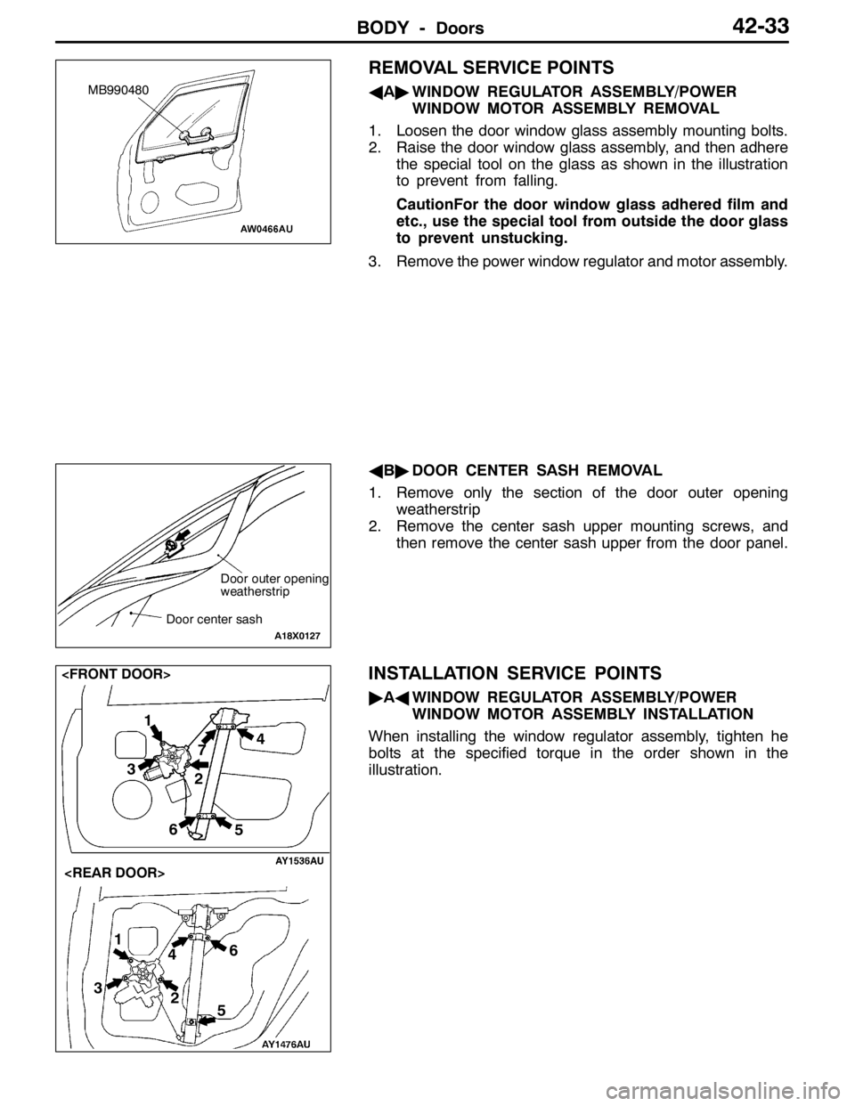
AA"WINDOW REGULATOR ASSEMBLY/POWER
WINDOW MOTOR ASSEMBLY REMOVAL
1. Loosen the door window glass assembly mounting bolts.
2. Raise the door window glass assembly, and then adhere
the special tool on the glass as shown in the illustration
to prevent from falling.
CautionFor the door window glass adhered film and
etc., use the special tool from outside the door glass
to prevent unstucking.
3. Remove the power window regulator and motor assembly.
AB"DOOR CENTER SASH REMOVAL
1. Remove only the section of the door outer opening
weatherstrip
2. Remove the center sash upper mounting screws, and
then remove the center sash upper from the door panel.
INSTALLATION SERVICE POINTS
"AAWINDOW REGULATOR ASSEMBLY/POWER
WINDOW MOTOR ASSEMBLY INSTALLATION
When installing the window regulator assembly, tighten he
bolts at the specified torque in the order shown in the
illustration.
MB990480
Door outer opening
weatherstrip
Door center sash
A18X0127
1
2 4
3
56
1
2
34
5 67
Page 1183 of 1449
BODY -Doors42-35
DOOR HANDLE AND LATCH
REMOVAL AND INSTALLATION
Pre-removal Operation
Door Trim Removal (Refer to P.42-27.)Post-installation Operation
DDoor Inside Handle Looseness Check (Refer to
P.42-24.)
DDoor Outside Handle Looseness Check (Refer to
P.42-23.)
DDoor Trim Installation (Refer to P.42-27.)
3
5
4 72
6
1
5.9±1.0 N·m
8.9±1.9 N·m
2
1
75 6
2.5±0.5 N·m
2.5±0.5 N·m
Door handle and door latch
removal steps
"CA1. Door inside handle
DWaterproof film (Refer to P.42-27.)
DDoor window glass lower runchan-
nel (Refer to P.42-38, 39.)
DDoor center sash (Refer to
P.42-32.)2. Door outside handle
3. Key cylinder
"BA4. Lower sash
5. Door latch assembly
6. Link
Door check removal steps
DWaterproof film (Refer to P.42-27.)
"AA7. Door check
INSTALLATION SERVICE POINTS
"AADOOR CHECK INSTALLATION
Install with the following identification marks upward.
ItemsIdentification mark
Front doorLeft side21L
Right side21R
Rear doorLeft side36L
Right side36R
Identification
mark