Page 1184 of 1449

BODY -DoorsBODY -Doors42-36
"BALOWER SASH INSTALLATION
Be sure to install the lower sash to the window rear sash
(at door) securely.
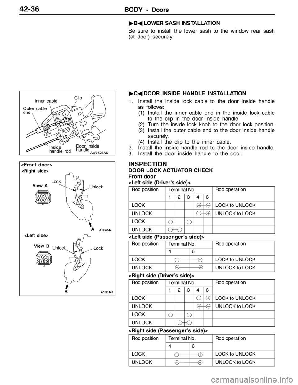
"CADOOR INSIDE HANDLE INSTALLATION
1. Install the inside lock cable to the door inside handle
as follows:
(1) Install the inner cable end in the inside lock cable
to the clip in the door inside handle.
(2) Turn the inside lock knob to the door lock position.
(3) Install the outer cable end to the door inside handle
securely.
(4) Install the clip to the inner cable.
2. Install the inside handle rod to the door inside handle.
3. Install the door inside handle to the door.
INSPECTION
DOOR LOCK ACTUATOR CHECK
Front door
Rod positionTerminal No.Rod operation
12346
LOCKLOCK to UNLOCK
UNLOCKUNLOCK to LOCK
LOCK
UNLOCK
Rod positionTerminal No.Rod operation
46
LOCKLOCK to UNLOCK
UNLOCKUNLOCK to LOCK
Rod positionTerminal No.Rod operation
12346
LOCKLOCK to UNLOCK
UNLOCKUNLOCK to LOCK
LOCK
UNLOCK
Rod positionTerminal No.Rod operationp
46
p
LOCKLOCK to UNLOCK
UNLOCKUNLOCK to LOCK
Door inside
handle
Inner cableClip
Outer cable
end
Inside
handle rod
B Unlock
View B
Lock
View A
Unlock Lock
A
Page 1185 of 1449
BODY -Doors42-37
Rear door
Rod positionTerminal No.Rod operationp
23
p
LOCKLOCK to UNLOCK
UNLOCKUNLOCK to LOCK
Rod positionTerminal No.Rod operationp
23
p
LOCKLOCK to UNLOCK
UNLOCKUNLOCK to LOCK
DOOR LOCK KEY CYLINDER SWITCH CONTINUITY
CHECK
Switch positionTerminal No.p
123123
LOCK
OFF
UNLOCK
BA
View ALock
Unlock
View B
UnlockLock
Page 1187 of 1449
BODY -Doors42-39
Sectional view of
clip positionSectional view of
clip position
5
4 3
21
Section A - A
Door
6
A
A
6
BB
Section B - B
Door
23
Door inner opening weatherstrip
removal steps
DScuff plate (Refer to GROUP 52A.)
DCenter pillar lower trim (Refer to
GROUP 52A.)
1. Door inner opening weatherstrip
Door outer opening weatherstrip
removal steps
2. Retainer weatherstrip
AA""AA3. Door outer opening weatherstrip
Door window glass runchannel
removal
4. Door window glass runchannelDoor beltline inner weatherstrip
removal steps
DDoor trim (Refer to P.42-27.)
5. Door beltline inner weatherstrip
Door beltline molding removal
steps
DDoor window glass (Refer to
P.42-32.)
DStationary glass (Refer to P.42-32.)
6. Door beltline molding
REMOVAL SERVICE POINT
AA"DOOR OUTER OPENING WEATHERSTRIP
REMOVAL
Make a tool as shown and remove the weatherstrip from
the door panel.15mm
4mm
8mm
Thickness
1mm
Page 1189 of 1449

BODY -Trunk lid42-41
TRUNK LID
REMOVAL AND INSTALLATION
2
34 56
7 89 10
111
12A
A
B
B5 5
99
14Measure of
length mm
15
4 9
12
8.9±1.9 N·m
Section A - A
Section B - B
Trunk lid weatherstrip removal
steps
DRear end trim (Refer to
GROUP 52A.)
"BA1. Trunk lid weatherstrip
Trunk lid release cable and trunk
lid release handle removal steps
DTrunk rear side trim (Left side)
(Refer to GROUP 52A.)
DRear seat (Refer to GROUP 52A.)
DCenter pillar lower trim (Refer to
GROUP 52A.)
DCowl side trim
DAccelerator pedal stopper
2. Trunk lid release handle
3. Trunk lid release cable
Trunk lid striker removal steps
DRear end trim (Refer to
GROUP 52A.)4. Trunk lid striker
Trunk lid panel removal steps
5. Trunk lid bumper
6. Trunk lid lock cylinder
7. Trunk lid latch assembly
8. Trunk lid hinge mounting bolt
9. Trunk lid panel assembly
Trunk lid latch assembly removal
7. Trunk lid latch assembly
Trunk lid hinge removal steps
DRear shelf trim
DRear seat (Refer to GROUP 52A.)
9. Trunk lid panel assembly
AA""AA10. Trunk lid torsion bar (Right side)
AA""AA11. Trunk lid torsion bar (Left side)
12. Trunk lid hinge
Page 1193 of 1449
51-1
EXTERIOR
CONTENTS
FRONT BUMPER 2....................
ADHESIVE 2..............................
FRONT BUMPER 2........................
REAR BUMPER 6.....................
SIDE AIR DAM, MOLDING AND
GARNISH 8...........................
SPECIAL TOOL 8.........................
ADHESIVE 8..............................
SIDE AIR DAM MOLDING GARNISH 9.....
REAR SPOILER 11....................
ADHESIVE 11.............................REAR SPOILER 12........................
WINDSHIELD WIPER AND WASHER 13.
SERVICE SPECIFICATIONS 13.............
TROUBLESHOOTING 13...................
ON - VEHICLE SERVICE 13.................
WINDSHIELD WIPER AND WASHER 14......
MARKS 20............................
OUTSIDE MIRROR 23.................
SPECIAL TOOL 23........................
OUTSIDE MIRROR 23......................
Page 1198 of 1449
EXTERIOR -Rear Bumper51-6
REAR BUMPER
REMOVAL AND INSTALLATION
Pre-removal and post-installation operations
DRemoval and installation of rear combination lamp (Refer to GROUP 54A.)
DRemoval and installation of rear end trim, washer tank lid and AYC reservoir tank lid (Refer to GROUP 52A – Trim.)
DRemoval and installation of rear splash shield
A A
B
B
Rear bumper assembly
Clip
Clip
Section A – A
Section B – B
Rear bumper assembly
Rear bumper assembly
Page 1199 of 1449
EXTERIOR -Rear Bumper51-7
DISASSEMBLY AND REASSEMBLY
1 32
54
Disassembly steps
1. License plate bracket
2. Rear bumper center reinforcement
AA""AA3. Rivet4. Rear bumper side plate
5. Rear bumper face
DISASSEMBLY SERVICE POINTS
AA"RIVET REMOVAL
Use the drill (ø 4.0 mm) to make a hole in the rivet for removal.
Drill
RivetFront
bumper
face
Page 1200 of 1449
EXTERIOR -Rear Bumper / Side Air Dam, Molding and Garnish51-8
REASSEMBLY SERVICE POINTS
"AARIVET INSTALLATION
Use the recommended tool shown in the illustration to secure
the rivet in the following procedure.
1. Insert the rivet into the main materials (rear bumper face
and rear bumper side plate.)
2. Insert the recommended tool into Part A of the rivet.
3. Maneuver the handle of the tool pressing the flange of
the rivet.
4. Particles of Part A of the rivet are cut off to be secured.
SIDE AIR DAM, MOLDING AND GARNISH
SPECIAL TOOL
ToolNumberNameApplication
MB990449Window molding
removerRemoval of roof drip molding
ADHESIVE
ApplicationBrand
Side air damDouble-sided tape [5 mm width 1.2 mm thickness]
Riveter
Bumper side
plate
Part A
Riveter
Rivet
Flange part
1
2
3
4Bumper face
Rivet
Bumper face