Page 1112 of 1449
PARKING BRAKES -Parking Brake Cable36-6
PARKING BRAKE CABLE
REMOVAL AND INSTALLATION
CAUTION
If the vehicle is equipped with the Brembo disc brake, during maintenance, take care not to contact
the parts or tools to the caliper because the paint of caliper will be scratched. And if there is
brake fluid on the caliper, wipe out quickly.
Pre-removal Operation
DRear Floor Console Assembly and Rear Console
Bracket Removal (Refer to GROUP 52A-Floor
Console.)
DRear Seat Cushion Assembly Removal (Refer to
GROUP 52A-Seat.)Post-installation Operation
DParking Brake Lever Stroke Check and Adjustment
(Refer to P.36-3.)
DRear Seat Cushion Installation (Refer to GROUP
52A-Seat.)
DRear Floor Console Assembly and Rear Console
Bracket Installation (Refer to GROUP 52A-Floor
Console.)
1
Removal steps
DShoe and lining assembly
(Refer to P.36-7.)
DParking brake cable connection
(Refer to P.36-5.)
1. Parking brake cable
Page 1113 of 1449
PARKING BRAKES -Parking Brake Drum36-7
PARKING BRAKE DRUM
REMOVAL AND INSTALLATION
CAUTION
If the vehicle is equipped with the Brembo disc brake, during maintenance, take care not to contact
the parts or tools to the caliper because the paint of caliper will be scratched. And if there is
brake fluid on the caliper, wipe out quickly.
5 11 14
1312
11 10
976
5 43
2 1
11
54�¶5N��m 118�¶19 N��m
8
Brake grease: Multipurpose grease
Removal steps
AA"1. Rear brake caliper assembly
2. Rear brake disc
"BA3. Shoe-to-anchor spring
4. Adjusting wheel spring
"AA5. Adjuster assembly
6. Strut
7. Strut-to-shoe spring
8. Shoe hold-down cup9. Shoe hold-down spring
10. Clip
11. Shoe and lining assembly
12. Rear hub assembly
(Refer to GROUP 27.)
13. Backing plate
14. Shoe hold-down pin
Page 1114 of 1449

PARKING BRAKES -Parking Brake Drum36-8
REMOVAL SERVICE POINT
AA"REAR BRAKE CALIPER ASSEMBLY REMOVAL
Remove the rear brake caliper assembly and support it with
wire or similar.
CAUTION: Brembo disc brake
Take care not to contact the parts or tools to the caliper
because the paint of caliper will be scratched. And if
there is brake fluid on the caliper, wipe out quickly.
INSTALLATION SERVICE POINTS
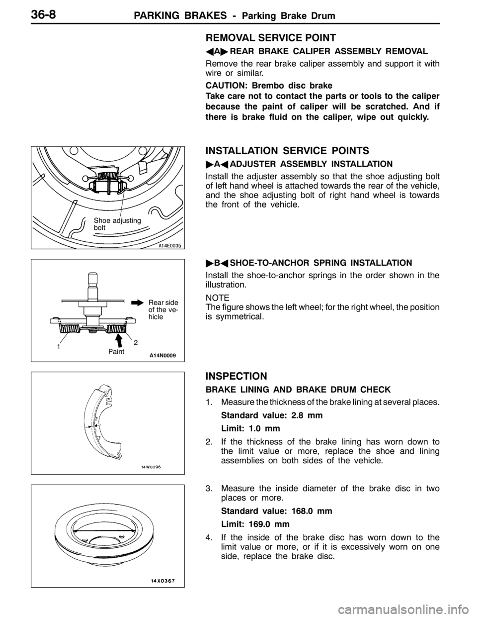
"AAADJUSTER ASSEMBLY INSTALLATION
Install the adjuster assembly so that the shoe adjusting bolt
of left hand wheel is attached towards the rear of the vehicle,
and the shoe adjusting bolt of right hand wheel is towards
the front of the vehicle.
"BASHOE-TO-ANCHOR SPRING INSTALLATION
Install the shoe-to-anchor springs in the order shown in the
illustration.
NOTE
The figure shows the left wheel; for the right wheel, the position
is symmetrical.
INSPECTION
BRAKE LINING AND BRAKE DRUM CHECK
1. Measure the thickness of the brake lining at several places.
Standard value: 2.8 mm
Limit: 1.0 mm
2. If the thickness of the brake lining has worn down to
the limit value or more, replace the shoe and lining
assemblies on both sides of the vehicle.
3. Measure the inside diameter of the brake disc in two
places or more.
Standard value: 168.0 mm
Limit: 169.0 mm
4. If the inside of the brake disc has worn down to the
limit value or more, or if it is excessively worn on one
side, replace the brake disc.
Shoe adjusting
bolt
Rear side
of the ve-
hicle
A14N0009
12
Paint
Page 1130 of 1449

STEERING - Power Steering Gear Box and Linkage37A-16
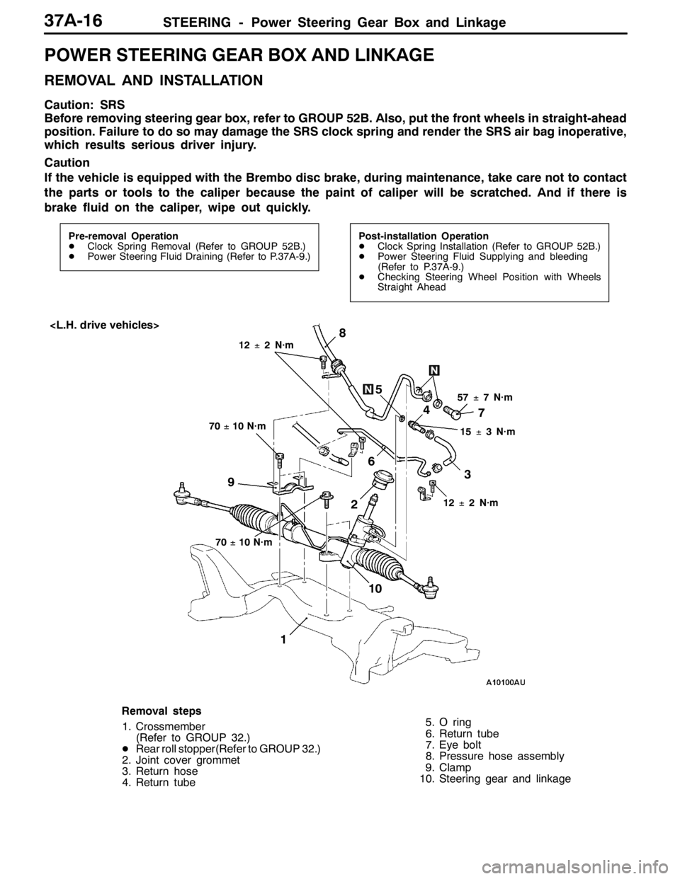
POWER STEERING GEAR BOX AND LINKAGE
REMOVAL AND INSTALLATION
Caution: SRS
Before removing steering gear box, refer to GROUP 52B. Also, put the front wheels in straight-ahead
position. Failure to do so may damage the SRS clock spring and render the SRS air bag inoperative,
which results serious driver injury.
Caution
If the vehicle is equipped with the Brembo disc brake, during maintenance, take care not to contact
the parts or tools to the caliper because the paint of caliper will be scratched. And if there is
brake fluid on the caliper, wipe out quickly.
Pre-removal Operation
DClock Spring Removal (Refer to GROUP 52B.)
DPower Steering Fluid Draining (Refer to P.37A-9.)Post-installation Operation
DClock Spring Installation (Refer to GROUP 52B.)
DPower Steering Fluid Supplying and bleeding
(Refer to P.37A-9.)
DChecking Steering Wheel Position with Wheels
Straight Ahead
17
6
3 4
57±7 N·m5
8
70±10 N·m
2
15±3 N·m
9
10
12±2 N·m 12±2 N·m
70±10 N·m
Removal steps
1. Crossmember
(Refer to GROUP 32.)
DRear roll stopper(Refer to GROUP 32.)
2. Joint cover grommet
3. Return hose
4. Return tube5. O ring
6. Return tube
7. Eye bolt
8. Pressure hose assembly
9. Clamp
10. Steering gear and linkage
Page 1145 of 1449
STEERING - Power Steering Oil Hoses37A-31
Pre-removal and Post-installation Operation
Power Steering Fluid Draining and Refilling (Refer to
P.37A-9.)
12±2 N·m
17
16
15
12
18±3 N·m
Crossmember
1
57±7 N·m
9
8 47
32 5
12±2 N·m15±3 N·m
18±2 N·m 12±2 N·m
49±10 N·m
52±7 N·m*
12±2 N·m
6
10
11
167±10 N·m
14 13
18
12±2 N·m
12±2 N·m
Removal steps
1. Oil reservoir
"BA2. Suction hose
3. Return hose
4. Return hose
5. Return tube
DStrut tower bar (Refer to GROUP 42.)
6. Return hose
DClock spring (Refer to GROUP 52B.)
DCrossmember bar
(Refer to GROUP 33A.)
DCenter member (Refer to GROUP 32.)
DFront exhaust pipe
(Refer to GROUP 15.)
7. Steering gear and joint connecting
bolt8. Rear roll stopper connecting bolt
9. Rear roll stopper
(Refer to GROUP 32.)
AA"10. Eye bolt
11. Gasket
"BA12. Pressure hose assembly
"AA13. O ring
14. Return hose
15. Return tube
AA"16. Return tube
17. O ring
DFront bumper (Refer to GROUP 51.)
DIntercooler (Refer to GROUP 15.)
18. Cooler tube assembly
Page 1146 of 1449
STEERING - Power Steering Oil Hoses37A-32
Pre-removal and Post-installation Operation
Power Steering Fluid Draining and Refilling (Refer to
P.37A-9.)
12±2 N·m
15
12
18±3 N·m
Crossmember
1
57±7 N·m
9
8 4
7
32 5
12±2 N·m
15±3 N·m
18±2 N·m 12±2 N·m
49±10 N·m
52±7 N·m*
12±2 N·m
6
10
11
167±10 N·m
14
13
12±2 N·m
Removal steps
1. Oil reservoir
"BA2. Suction hose
3. Return hose
4. Return hose
5. Return tube
DStrut tower bar (Refer to GROUP 42.)
6. Return hose
DClock spring (Refer to GROUP 52B.)
DCrossmember bar
(Refer to GROUP 33A.)
DCenter member (Refer to GROUP 32.)
DFront exhaust pipe
(Refer to GROUP 15.)7. Steering gear and joint connecting
bolt
8. Rear roll stopper connecting bolt
AA"9. Eye bolt
10. Gasket
"BA11. Pressure hose assembly
"AA12. O ring
AA"13. Return tube
14. O ring
DFront bumper (Refer to GROUP 51.)
DIntercooler (Refer to GROUP 15.)
15. Cooler tube assembly
Page 1149 of 1449

42-1
BODY
CONTENTS
HOOD2 .................................
ON-VEHICLE SERVICE 2..................
Adjustment of Clearance around Hood 2......
Adjustment of Alignment of Hood Stepped
Portion and Hood Striker 2..................
Adjustment of Hood Height 2.................
HOOD 3..................................
FENDER4 ..............................
SPECIAL TOOL 4.........................
FENDER 5................................
FUEL FILLER DOOR7 .................
STRUT TOWER BAR AND REAR END
CROSS BAR8 ...........................
WINDOW GLASS9 .....................
ADHESIVE 9..............................
SPECIAL TOOLS 9........................
WINDOW REPAIR 9.......................
WINDSHIELD 11...........................
REAR WINDOW GLASS 16................
DOORS19 ..............................
SERVICE SPECIFICATIONS 19.............ADHESIVES 19............................
SPECIAL TOOLS 19.......................
TROUBLESHOOTING 20...................
ON-VEHICLE SERVICE 20.................
Door Adjustment 20.........................
Door Window Glass Adjustment 21...........
Adjustment and Replacement during Power
Window Malfunction 22......................
Power Window Safety Mechanism Check 22..
Power Window Timer Function Check 22......
Door Outside Handle Looseness Check 23....
Power Window Operation Current Check 23...
Circuit Breaker Check 23....................
Power Window Check 23....................
Door Inside Handle Looseness Check and
Adjustment 24...............................
DOOR ASSEMBLY 25......................
DOOR TRIM AND
WATERPROOF FILM 27....................
DOOR GLASS AND REGULATOR 32.......
DOOR HANDLE AND LATCH 35...........
WINDOW GLASS RUNCHANNEL AND
DOOR OPENING WEATHERSTRIP 38.......
TRUNK LID41 ..........................
Page 1155 of 1449
BODY -Fuel Filler Door42-7
FUEL FILLER DOOR
REMOVAL AND INSTALLATION
Pre-removal and Post-installation Operations
DRear Seat Removal and Installation. (Refer to GROUP
52A.)
DFront Scuff Plate (Driver’s Side), Rear Scuff Plate(Driver’s Side), Center Pillar Lower Trim (Driver’s
Side), Quarter Trim (Driver’s Side) Removal and
Installation (Refer to GROUP 52A – Trim.)
5
1
3 4 3
2
5.0±1.0 N·m
Adjustment of clearance around
fuel filler door
Removal steps
1. Fuel filler door panel assembly
2. Clip
3. Fuel filler door hook assembly4. Fuel filler door lock release cable
5. Fuel filler door lock release handle