Page 1024 of 1449
POWER PLANT MOUNT - Crossmember32-10
35±5 N·m*1
108±10 N·m52±7 N·m*1
18±2 N·m
69±9 N·m
25±4 N·m
21±4 N·m
49±10 N·m167±9 N·m
13 45
89
1011126
7
186±10 N·m*2
15±3 N·m
13
2
39±5 N·m
39±5 N·m
57±7 N·m
21±4 N·m
Removal steps
1. Lower arm and knuckle connection
2. Stabilizer link
AA"3. Lower arm assembly
4. Pressure hose connection
5. Return hose connection
6. Steering shaft assembly and gear
box connecting bolt
AB"7. Tie rod end and knuckle connec-
tion8. Rear roll stopper connection bolt
AC"9. Crossmember assembly
10. Rear roll stopper
"AA11. Stabilizer bar
12. Steering gear and linkage
13. Crossmember
Page 1030 of 1449

FRONT SUSPENSION -Special Tools/On-vehicle Service33A-4
Tools UseName Number
MB990800Ball joint remover &
installerLower arm ball joint dust cover press-in
MB990651BarLower arm pillow ball bushing removal and
press-fitting
MB990816Bushing remover &
installer base
MB991576Base
MB990635,
MB991113 or
MB991406Steering linkage
pullerTie rod end and knuckle disconnection
ON-VEHICLE SERVICE
WHEEL ALIGNMENT CHECK AND
ADJUSTMENT
Measure the wheel alignment with the vehicle parked on a
level surface.
The front suspension, steering system, and wheels should be
serviced to normal condition prior to measurement of wheel
alignment.
TOE-IN
Standard value:
At the centre of tyre tread 0±2mm
Toe angle (per wheel) 0_00’±05’
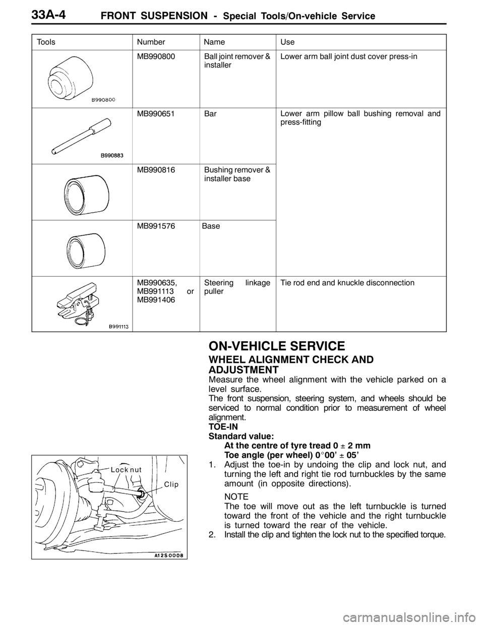
1. Adjust the toe-in by undoing the clip and lock nut, and
turning the left and right tie rod turnbuckles by the same
amount (in opposite directions).
NOTE
The toe will move out as the left turnbuckle is turned
toward the front of the vehicle and the right turnbuckle
is turned toward the rear of the vehicle.
2. Install the clip and tighten the lock nut to the specified torque.
Clip
Lock nut
Page 1039 of 1449

FRONT SUSPENSION -Stabilizer Bar33A-13
Pre-removal Operation
DSteering Wheel and Air Bag Module Assembly
Removal (Refer to GROUP 37A.)
DClock Spring Removal (Refer to GROUP 52B.)
DCrossmember Bar Removal (Refer to P.33A-15.)
DCentermember Removal (Refer to GROUP 32.)
DFront Exhaust Pipe Removal (Refer to GROUP 15.)Post-installation Operation
DFront Exhaust Pipe Installation (Refer to GROUP
15.)
DCentermember Installation (Refer to GROUP 32.)
DCrossmember Bar Installation (Refer to P.33A-15.)
DClock Spring Installation (Refer to GROUP 52B.)
DSteering Wheel and Air Bag Module Assembly
Installation (Refer to GROUP 37A.)
DCheck the Dust Cover for Cracks or Damage by
Pushing it with Finger.
DChecking Steering Wheel Position with Wheels
Straight Ahead
DFront Wheel Alignment Check and Adjustment
(Refer to P.33A-4.)
3
4
10
21±4N·m
51
1
2
25±5N·m
18±2N·m
108±10 N·m
52±7N·m*
49±10 N·m
167±9N·m
7
8
9
6
39±5N·m
39±5N·m
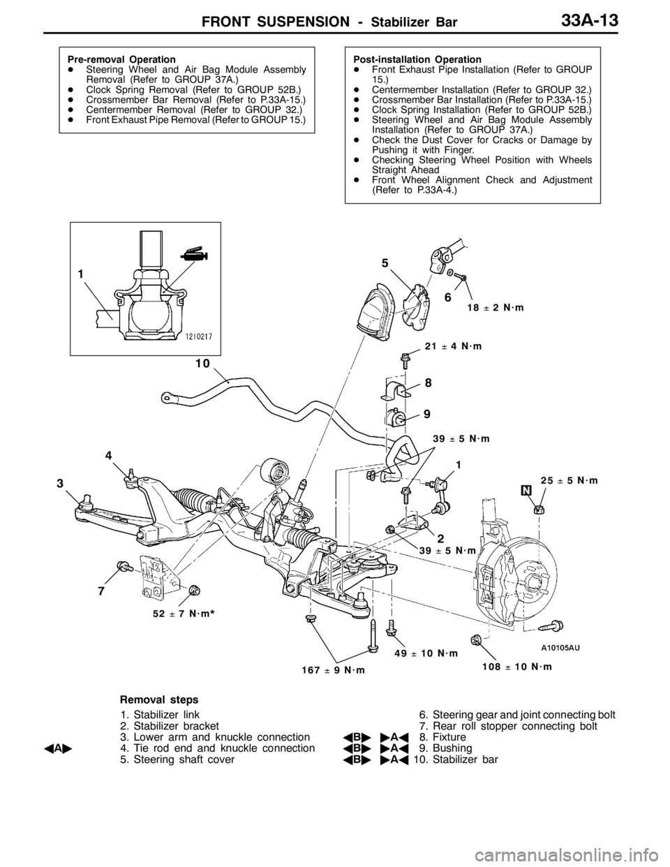
Removal steps
1. Stabilizer link
2. Stabilizer bracket
3. Lower arm and knuckle connection
AA"4. Tie rod end and knuckle connection
5. Steering shaft cover6. Steering gear and joint connecting bolt
7. Rear roll stopper connecting bolt
AB""AA8. Fixture
AB""AA9. Bushing
AB""AA10. Stabilizer bar
Page 1045 of 1449

BASIC BRAKE SYSTEM -General Information35A-3
GENERAL INFORMATION
The brake system offers high dependability and durability along with improved braking performance and
brake sensitivity.
SERVICE PRECAUTION
Take care not to contact the parts or tools to the caliper because the paint of caliper will be scratched.
SPECIFICATIONS
ItemsSpecifications
Master cylinderTypeTandem type
I.D. mm26.9
Brake boosterTypeVacuum type, tandem
Effective dia. of power cylinder mm205 + 230
Boosting ratio4.5 (Pedal depressing force: 230 N)
Rear wheel hydraulic
controlmethod
Vehicles with ABS Electronic brake-force distribution (EBD)
control methodVehicles without ABS Proportioning valves
Proportioning valves
VehicleswithoutABS
TypeSingle type¢2
Decompression ratio0.25
Front brakes
RS(standard)
TypeFloating caliper, 2 piston, ventilated disc
Disc effective dia.¢thickness mm227¢24
Wheel cylinder I.D. mm42.9 (¢2)
Pad thickness mm10.0
Clearance adjustmentAutomatic
Front brakes
Type4 opposed piston, ventilated disc
Disc effective dia.¢thickness mm263¢32
Wheel cylinder I.D. mm40.0 (¢2), 46.0 (¢2)
Pad thickness mm10.0
Clearance adjustmentAutomatic
Rear brakes
RS(standard)
TypeFloating caliper, 1 piston, ventilated disc
Disc effective dia.¢thickness mm237¢20
Wheel cylinder I.D. mm34.9
Pad thickness mm10.0
Clearance adjustmentAutomatic
Rear brakes
Type2 opposed piston, ventilated disc
Disc effective dia.¢thickness mm252¢22
Wheel cylinder I.D. mm40.0 (¢2)
Pad thickness mm9.0
Clearance adjustmentAutomatic
Brake fluidDOT3 or DOT4
Page 1046 of 1449
BASIC BRAKE SYSTEM -General Information35A-4
CONSTRUCTION DIAGRAM
Brake booster*
Rear disc brake
Parking brake
Front disc brake Master cylinder*Hydraulic unit*
Brake booster*
Rear disc brake
Parking brake
Front disc brake Master cylinder and
proportioning valves*
NOTE
For R.H. drive vehicles, only the position indicated by the * is symmetrical.
Page 1047 of 1449
Page 1053 of 1449

BASIC BRAKE SYSTEM -On-vehicle Service35A-11
BRAKE FLUID LEVEL SENSOR CHECK
The brake fluid level sensor is in good condition if there is
no continuity when the float surface is above “MIN” and if
there is continuity when the float surface is below “MIN”.
DISC BRAKE PAD CHECK AND REPLACEMENT
NOTE
The wear indicator contacts the brake disc when the brake
pad thickness reaches approximately 2 mm and emit a
squealing sound to warn the driver.
1. Check the brake pad thickness through the caliper body
check port.
Standard value: 10.0 mm
Limit: 2.0 mm
2. When the thickness is less than the limit, always replace
the pads at an axle set.
3. Remove the pin bolt. Pivot the caliper assembly and hold
it with wires.
Caution
Do not wipe off the special grease that is on the pin
or allow it to contaminate the pin.
4. Remove the following parts from the caliper support.
1. Pad and wear indicator assembly
2. Pad assembly
3. Clip
4. Outer shim
5. In order to measure the brake drag force after pad
installation, measure the rotary-sliding resistance of the
hub with the pads removed. (Refer to P.35A-21.)
6. Install the pads and caliper assembly, and then check
the brake drag force. (Refer to P.35A-21.)
14Z0017
Front Rear
Front Rear
Front Rear
12 34
3
1
2 3
4
3
Page 1054 of 1449

BASIC BRAKE SYSTEM -On-vehicle Service35A-12
Caution
Take care not to contact the parts or tools to the caliper
because the paint of caliper will be scratched. And if
there is brake fluid on the caliper, wipe out quickly.
NOTE
The wear indicator contacts the brake disc when the brake
pad thickness reaches approximately 2 mm and emit a
squealing sound to warn the driver.
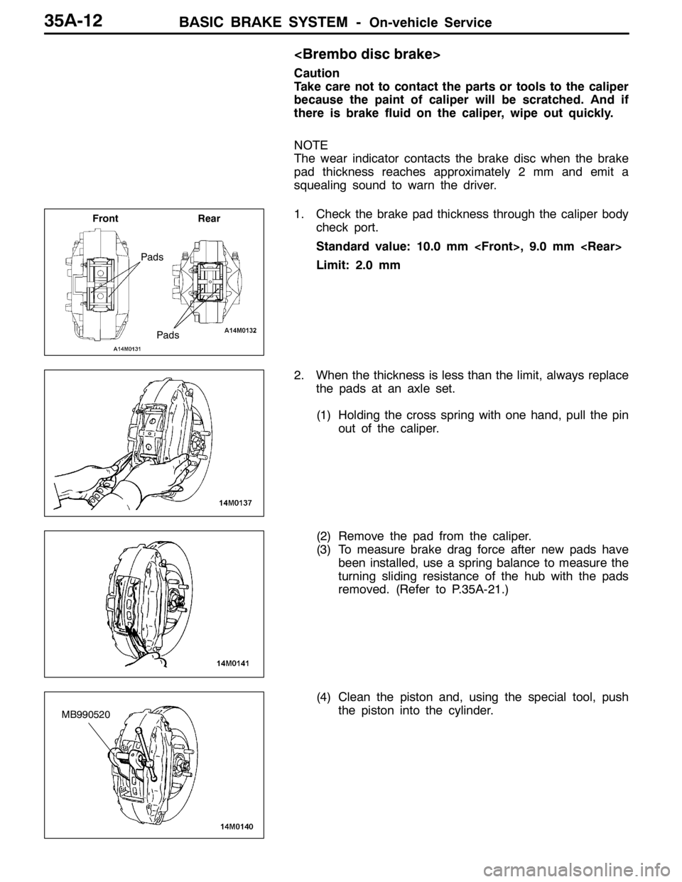
1. Check the brake pad thickness through the caliper body
check port.
Standard value: 10.0 mm , 9.0 mm
Limit: 2.0 mm
2. When the thickness is less than the limit, always replace
the pads at an axle set.
(1) Holding the cross spring with one hand, pull the pin
out of the caliper.
(2) Remove the pad from the caliper.
(3) To measure brake drag force after new pads have
been installed, use a spring balance to measure the
turning sliding resistance of the hub with the pads
removed. (Refer to P.35A-21.)
(4) Clean the piston and, using the special tool, push
the piston into the cylinder.
Pads
Front Rear
Pads
MB990520