Page 1091 of 1449

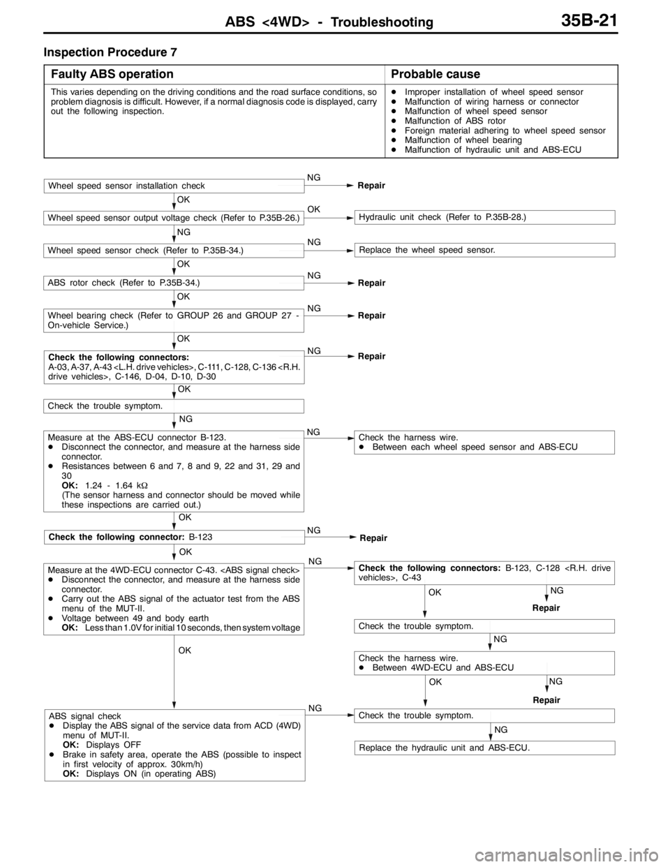
ABS <4WD> -Troubleshooting35B-21
Inspection Procedure 7
Faulty ABS operation
Probable cause
This varies depending on the driving conditions and the road surface conditions, so
problem diagnosis is difficult. However, if a normal diagnosis code is displayed, carry
out the following inspection.DImproper installation of wheel speed sensor
DMalfunction of wiring harness or connector
DMalfunction of wheel speed sensor
DMalfunction of ABS rotor
DForeign material adhering to wheel speed sensor
DMalfunction of wheel bearing
DMalfunction of hydraulic unit and ABS-ECU
OK
OK
Check the following connector:B-123
NG
Measure at the ABS-ECU connector B-123.
DDisconnect the connector, and measure at the harness side
connector.
DResistances between 6 and 7, 8 and 9, 22 and 31, 29 and
30
OK:1.24 - 1.64 kΩ
(The sensor harness and connector should be moved while
these inspections are carried out.)NG
OK
Check the trouble symptom.
OK
NG
Repair
OK
Wheel bearing check (Refer to GROUP 26 and GROUP 27 -
On-vehicle Service.)NG
Repair
OK
ABS rotor check (Refer to P.35B-34.)NG
Repair
NG
Wheel speed sensor check (Refer to P.35B-34.)NGReplace the wheel speed sensor.
OK
Wheel speed sensor output voltage check (Refer to P.35B-26.)OKHydraulic unit check (Refer to P.35B-28.)
Wheel speed sensor installation checkNG
Repair
Check the harness wire.
DBetween each wheel speed sensor and ABS-ECU
NG
Repair
NG
NG
RepairOK
Check the following connectors:B-123, C-128
vehicles>, C-43
NG
Check the trouble symptom.
RepairNG
OK
Check the harness wire.
DBetween 4WD-ECU and ABS-ECU OK
Measure at the 4WD-ECU connector C-43.
DDisconnect the connector, and measure at the harness side
connector.
DCarry out the ABS signal of the actuator test from the ABS
menu of the MUT-II.
DVoltage between 49 and body earth
OK:Less than 1.0V for initial 10 seconds, then system voltage
NGABS signal check
DDisplay the ABS signal of the service data from ACD (4WD)
menu of MUT-II.
OK:Displays OFF
DBrake in safety area, operate the ABS (possible to inspect
in first velocity of approx. 30km/h)
OK:Displays ON (in operating ABS)
NG
Check the trouble symptom.
Replace the hydraulic unit and ABS-ECU.
Check the following connectors:
A-03, A-37, A-43 , C-111, C-128, C-136
drive vehicles>, C-146, D-04, D-10, D-30
Page 1097 of 1449

ABS <4WD> -On-vehicle Service35B-27
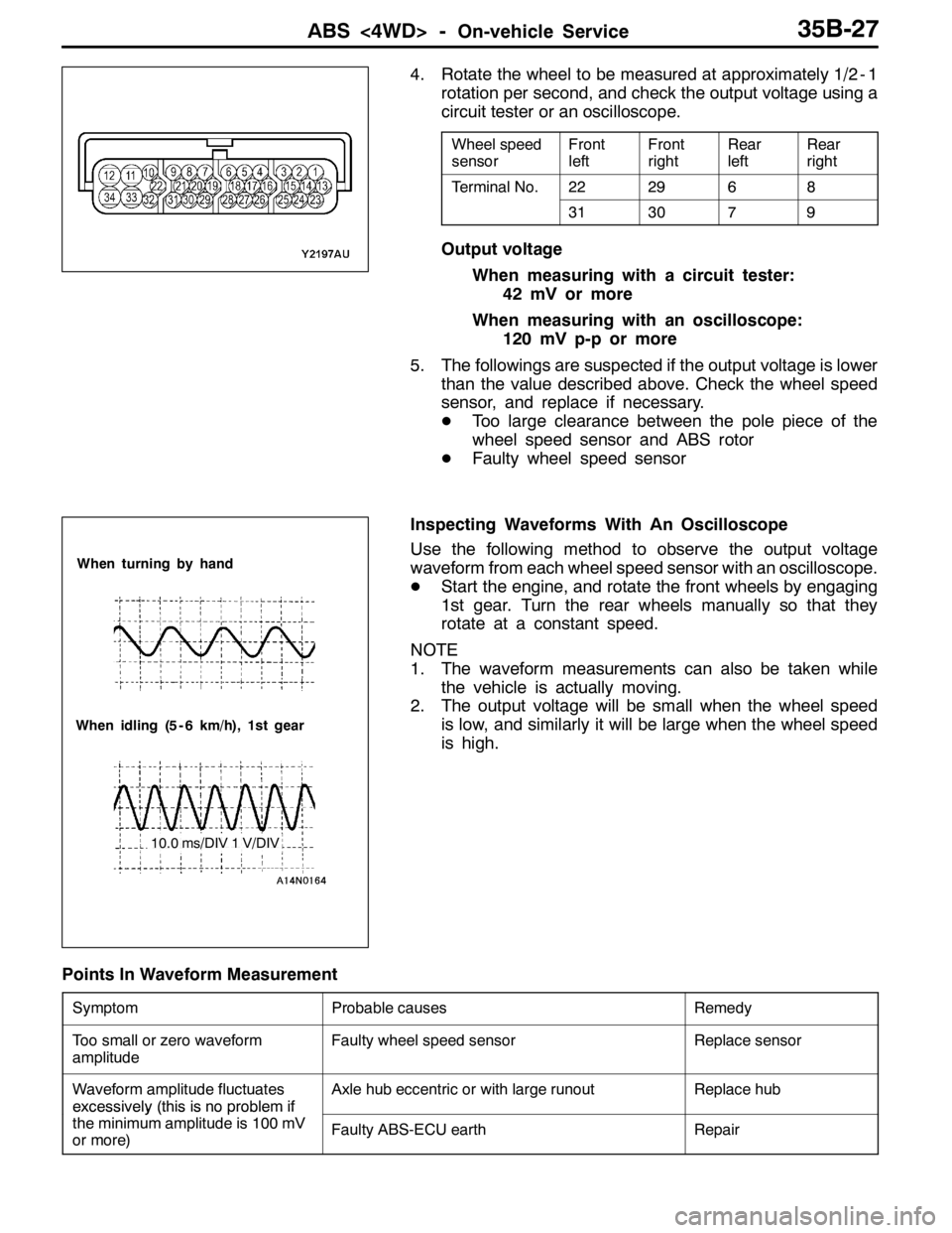
4. Rotate the wheel to be measured at approximately 1/2 - 1
rotation per second, and check the output voltage using a
circuit tester or an oscilloscope.
Wheel speed
sensorFront
leftFront
rightRear
leftRear
right
Terminal No.222968
313079
Output voltage
When measuring with a circuit tester:
42 mV or more
When measuring with an oscilloscope:
120 mV p-p or more
5. The followings are suspected if the output voltage is lower
than the value described above. Check the wheel speed
sensor, and replace if necessary.
DToo large clearance between the pole piece of the
wheel speed sensor and ABS rotor
DFaulty wheel speed sensor
Inspecting Waveforms With An Oscilloscope
Use the following method to observe the output voltage
waveform from each wheel speed sensor with an oscilloscope.
DStart the engine, and rotate the front wheels by engaging
1st gear. Turn the rear wheels manually so that they
rotate at a constant speed.
NOTE
1. The waveform measurements can also be taken while
the vehicle is actually moving.
2. The output voltage will be small when the wheel speed
is low, and similarly it will be large when the wheel speed
is high.
Points In Waveform Measurement
SymptomProbable causesRemedy
Too small or zero waveform
amplitudeFaulty wheel speed sensorReplace sensor
Waveform amplitude fluctuates
excessivel
y(this is noproblem if
Axle hub eccentric or with large runoutReplace hub
excessively(thisisnoproblemif
the minimum amplitude is 100 mV
or more)Faulty ABS-ECU earthRepair
When turning by hand
When idling (5 - 6 km/h), 1st gear
10.0 ms/DIV 1 V/DIV
Page 1118 of 1449

STEERING -Service Specifications/Lubricants/Sealant/Special Tools37A-4
SERVICE SPECIFICATIONS
ItemsStandard valueLimit
Steering wheel free play mmwhen engine running-30 or less
with engine stopped0-10-
Steering angleInner wheel31_45’±1_30’-
Outer wheel 27_15’-
Ball joint turning torque N·m1.0 - 3.0-
Stationary steering effort NSteering effort32 or less-
Fluctuation allowance6.0 or less-
Oil pump relief pressure MPa8.4 - 9.0-
Pressure under no-load conditions MPa0.2 - 0.8-
Steering gear retention hydraulic pressure MPa8.4 - 9.0-
Oil pressure switch operating
pressureMPa
OFF→ON1.8 - 2.4-
pressure MPaON→OFF1.0 - 2.4-
Total pinion torque N·mTotal rotation torque0.8 - 1.8-
Torque variation0.49 or less-
Tie rod joint swing resistance N (Tie rod joint swing torque N·m)8 - 27 (1.5 - 4.9)-
Opening dimension of special tool (MB991561) mm2.9-
Band crimped width mm2.4 - 2.8-
LUBRICANTS
ItemsSpecified lubricantQuantity
Power steering fluidAutomatic transmission fluid DEXRONIIApprox. 1.0 L
Tie rod bellowsSilicone greaseAs required
Pinion and valve assemblyRepair kit greaseAs required
Rack assembly
SEALANT
ItemsSpecified sealantRemarks
Toe boad (steering shaft cover
mounting bolt hole)3M ATD Part No. 8513 or equivalentDrying sealant
Rack support cover end plug3M ATD Part No. 8661, 8663 or equivalentSemi-drying sealant
SPECIAL TOOLS
ToolNumberNameUse
MB990635,
MB991113 or
MB991406Steering linkage
pullerDisconnection of tie rod end
Page 1124 of 1449

STEERING -On-vehicle Service37A-10
9. If the level changes more than 5 mm, the air is badly
bled. So, bleed air again.
Caution
(1) If the fluid level rises suddenly after the engine
is stopped, the bleeding is incomplete.
(2) Incomplete bleeding causes abnormal noises
from the pump and the flow-control valve. This
could lessen the life of the pump and the other
parts.
OIL PUMP PRESSURE TEST
1. Disconnect the pressure hose from the oil pump, and
then connect the special tools.
2. Bleed the air, and then turn the steering wheel several
times while the vehicle is not moving so that the
temperature of the fluid rises to approximately 50 - 60_C.
3. Start the engine and idle it at 1,000±100 r/min.
4. Fully close the shut-off valve of the pressure gauge and
measure the oil pump relief pressure to confirm that it
is within the standard value range.
Standard value: 8.4 - 9.0 MPa
5. If the standard value is not met, the oil pump is defective.
So, replace the oil pump. Then, measure oil pressure
again.
6. With the pressure gauge shut - off valve fully open, check
the hydraulic pressure in unladen condition.
Standard value: 0.2 - 0.8 MPa
7. If the standard value is not met, the oil line or steering
gear is probably defective. So, repair and measure oil
pressure again.
8. Turn the steering wheel fully either left or right and check
the retention hydraulic pressure.
Standard value: 8.4 - 9.0 MPa
9. If the pressure is below the standard value, disassemble
and reassemble the steering gear. If above, replace the
oil pump. Then, measure oil pressure again.
10. Remove the special tools, and tighten the pressure hose
to the specified torque.
Tightening torque: 18±3 N·m
11. Bleed the system.
Fluid level change: Within 5 mm
While engine
runningWhile engine
stopped
Temperature
gaugePressure
gauge
(MB990662)Shut-off valve
Oil
pumpOil reservoir
Adapter
(MB990994)
Adapter
(MB990993)
Page 1131 of 1449

STEERING - Power Steering Gear Box and Linkage37A-17
17 6 2
3 4
15±3 N·m
57±7 N·m
5
70±10 N·m
Removal steps
1. Crossmember
(Refer to GROUP 32.)
2. Joint cover grommet
3. Return hose connection4. Return tube
5. Pressure hose connection
6. Clamp
7. Steering gear and linkage
INSPECTION
GEAR BOX PINION TOTAL ROTATION TORQUE CHECK
Caution
Secure the steering gear box and linkage in their mounting
positions only. Otherwise, deformation or damage could
result.
1. Using the special tool, turn the pinion gear at a speed
of one rotation per 4 to 6 seconds to measure total rotation
torque.
Standard values:
Total rotation torque: 0.8 – 1.8 N·m
Torque fluctuation: 0.49 N·m or less
NOTE
(1) Remove the bellows from the rack housing before
measuring.
(2) Measure the total rotation torque by turning the special
tool left and right 180_from the neutral position.
2. If the standard values are not met, adjust the pinion total
rotation torque. (Refer to P.37A-26.)
3. In case the adjustment is impossible, disassemble and
check the components, and repair if necessary.
MB991006
Page 1133 of 1449

STEERING - Power Steering Gear Box and Linkage37A-19
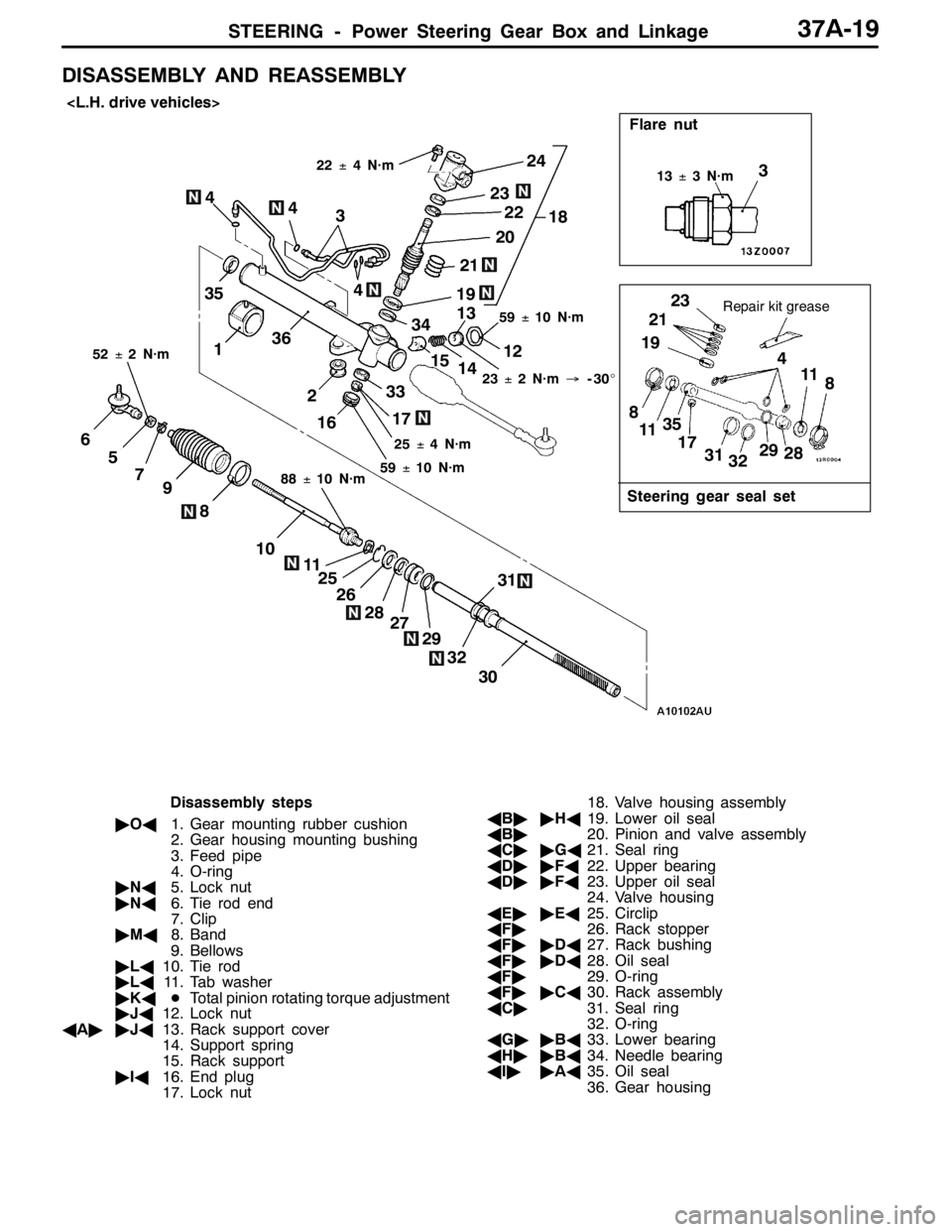
DISASSEMBLY AND REASSEMBLY
31
30
28
11
10
8
97
5
6
29
2618
33
22
20
Flare nut
21
23
36
32 17
1615
14 13
12 3
19
Steering gear seal set
Repair kit grease35
23
21
19
8
1135
17
32 3129
2811
8 3
4 4
27 25
22±4 N·m
25±4 N·m59±10 N·m
88±10 N·m 52±2 N·m
13±3 N·m
1
2 4
23±2 N·m→-30_
59±10 N·m
34
24
4
Disassembly steps
"OA1. Gear mounting rubber cushion
2. Gear housing mounting bushing
3. Feed pipe
4. O-ring
"NA5. Lock nut
"NA6. Tie rod end
7. Clip
"MA8. Band
9. Bellows
"LA10. Tie rod
"LA11. Tab washer
"KADTotal pinion rotating torque adjustment
"JA12. Lock nut
AA""JA13. Rack support cover
14. Support spring
15. Rack support
"IA16. End plug
17. Lock nut18. Valve housing assembly
AB""HA19. Lower oil seal
AB"20. Pinion and valve assembly
AC""GA21. Seal ring
AD""FA22. Upper bearing
AD""FA23. Upper oil seal
24. Valve housing
AE""EA25. Circlip
AF"26. Rack stopper
AF""DA27. Rack bushing
AF""DA28. Oil seal
AF"29. O-ring
AF""CA30. Rack assembly
AC"31. Seal ring
32. O-ring
AG""BA33. Lower bearing
AH""BA34. Needle bearing
AI""AA35. Oil seal
36. Gear housing
Page 1134 of 1449

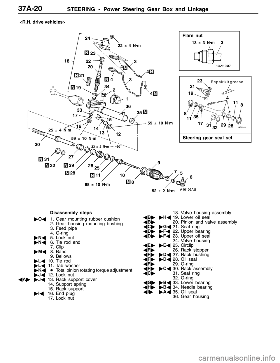
STEERING - Power Steering Gear Box and Linkage37A-20
18
24
23
22
21
20
34
36
33
17
1615
14
13
123
19
3523
21
19
8
1135
17
31
3229
2811
8
3
4 4
31
32
27
29
28
26
25
1110
8
9
756
304
22±4 N·m
25±4 N·m
59±10 N·m
59±10 N·m
88±10 N·m
52±2 N·m
23±2 N·m→–30_
13±3 N·m
1 2
4
Flare nut
Steering gear seal set
Repair kit grease3
4
Disassembly steps
"OA1. Gear mounting rubber cushion
2. Gear housing mounting bushing
3. Feed pipe
4. O-ring
"NA5. Lock nut
"NA6. Tie rod end
7. Clip
"MA8. Band
9. Bellows
"LA10. Tie rod
"LA11. Tab washer
"KADTotal pinion rotating torque adjustment
"JA12. Lock nut
AA""JA13. Rack support cover
14. Support spring
15. Rack support
"IA16. End plug
17. Lock nut18. Valve housing assembly
AB""HA19. Lower oil seal
AB"20. Pinion and valve assembly
AC""GA21. Seal ring
AD""FA22. Upper bearing
AD""FA23. Upper oil seal
24. Valve housing
AE""EA25. Circlip
AF"26. Rack stopper
AF""DA27. Rack bushing
AF""DA28. Oil seal
AF"29. O-ring
AF""CA30. Rack assembly
AC"31. Seal ring
32. O-ring
AG""BA33. Lower bearing
AH""BA34. Needle bearing
AI""AA35. Oil seal
36. Gear housing
Page 1135 of 1449
STEERING - Power Steering Gear Box and Linkage37A-21
Lubrication and Sealing Points
Fluid:
Automatic transmission
fluid DEXRON II
Fluid:
Automatic transmission
fluid DEXRON II
Fluid:
Automatic transmission
fluid DEXRON II
Fluid:
Automatic transmission
fluid DEXRON II
Grease: Repair kit grease
Sealant: 3M ATD part No. 8661,
8663 or equivalent
Fluid:
Automatic transmission
fluid DEXRON II
Grease: Repair kit grease
Fluid:
Automatic transmission
fluid DEXRON II
Grease: Silicone grease