Page 926 of 1449
PROPELLER SHAFT - Propeller Shaft25-8
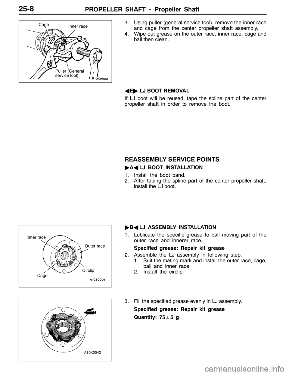
3. Using puller (general service tool), remove the inner race
and cage from the center propeller shaft assembly.
4. Wipe out grease on the outer race, inner race, cage and
ball then clean.
AE"LJ BOOT REMOVAL
If LJ boot will be reused, tape the spline part of the center
propeller shaft in order to remove the boot.
REASSEMBLY SERVICE POINTS
"AALJ BOOT INSTALLATION
1. Install the boot band.
2. After taping the spline part of the center propeller shaft,
install the LJ boot.
"BALJ ASSEMBLY INSTALLATION
1. Lublicate the specific grease to ball moving part of the
outer race and innerer race.
Specified grease: Repair kit grease
2. Assemble the LJ assembly in following step.
1. Suit the mating mark and install the outer race, cage,
ball and inner race.
2. Install the circlip.
3. Fill the specified grease evenly in LJ assembly.
Specified grease: Repair kit grease
Quantity: 75±5g
Puller (General
service tool)Inner race Cage
CirclipOuter race Inner race
Cage
Page 931 of 1449
FRONT AXLE -Service Specifications/Lubricants/Special Tools26-3
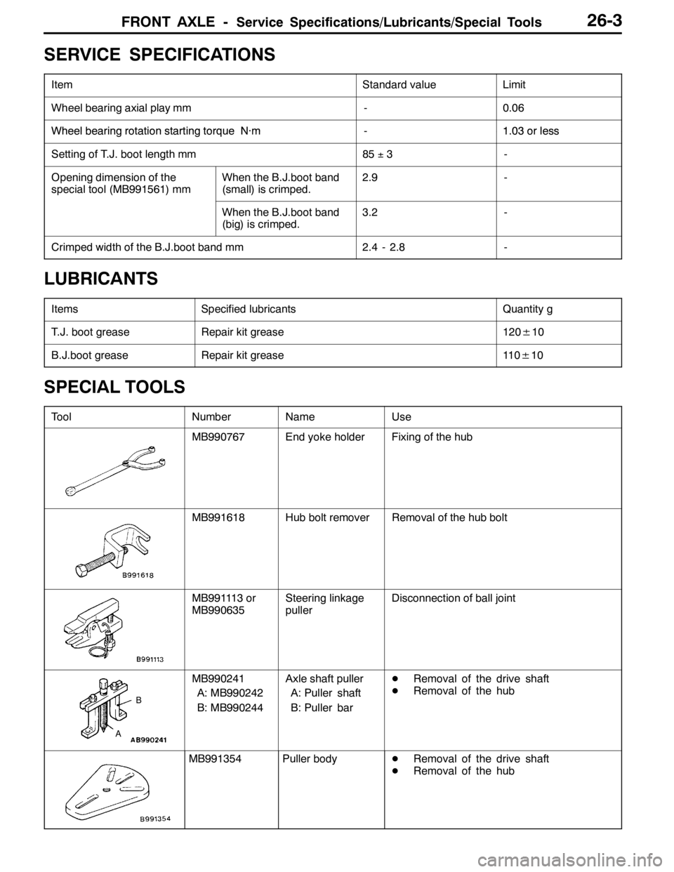
SERVICE SPECIFICATIONS
ItemStandard valueLimit
Wheel bearing axial play mm-0.06
WheelbearingrotationstartingtorqueN·m-103orlessWheelbearing rotation startingtorqueN·m-1.03orless
Setting of T.J. boot length mm85±3-
Opening dimension of the
special tool (MB991561) mmWhen the B.J.boot band
(small) is crimped.2.9-
When the B.J.boot band
(big) is crimped.3.2-
Crimped width of the B.J.boot band mm2.4 - 2.8-
LUBRICANTS
ItemsSpecified lubricantsQuantity g
T.J. boot greaseRepair kit grease120±10
B.J.boot greaseRepair kit grease11 0±10
SPECIAL TOOLS
ToolNumberNameUse
MB990767End yoke holderFixing of the hub
MB991618Hub bolt removerRemoval of the hub bolt
MB991113 or
MB990635Steering linkage
pullerDisconnection of ball joint
A
B
MB990241
A: MB990242
B: MB990244Axle shaft puller
A: Puller shaft
B: Puller barDRemoval of the drive shaft
DRemoval of the hub
MB991354Puller bodyDRemoval of the drive shaft
DRemoval of the hub
Page 941 of 1449
FRONT AXLE -Drive Shaft26-13
DISASSEMBLY AND REASSEMBLY
Caution
(1) On the vehicles with ABS or ACD, when the drive shaft is disassembled or reassembled, be
careful not to interfere with the rotor for wheel speed sensor installed to the B.J. outer race
to prevent the rotor from damage.
(2) Never disassemble the B.J. assembly except when replacing the B.J. boot.
2
6
4
3
5
7
1
4
2
43
61
2
4
51
2
9
10
1
8
8
97
6
T.J. repair kitT.J. boot repair kit B.J. boot repair kit
Disassembly steps
"BA1. T.J. boot band (large)
"BA2. T.J. boot band (small)
AA""AA3. T.J. case
4. Snap ring
AA""AA5. Spider assemblyAB"6. T.J. boot
7. B.J. boot band (large)
8. B.J. boot band (small)
9. B.J. boot
10. B.J. assembly
Page 942 of 1449
FRONT AXLE -Drive Shaft26-14
DISASSEMBLY SERVICE POINTS
AA"T.J. CASE/SPIDER ASSEMBLY REMOVAL
1. Wipe off grease from the spider assembly and the inside
of the T.J. case.
2. Always clean the spider assembly when the grease
contains water or foreign material.
Caution
Do not disassemble the spider assembly.
AB"T.J. BOOT REMOVAL
1. Wipe off grease from the shaft spline.
2. When reusing the T.J. boot, wrap plastic tape around
the shaft spline to avoid damaging the boot.
REASSEMBLY SERVICE POINTS
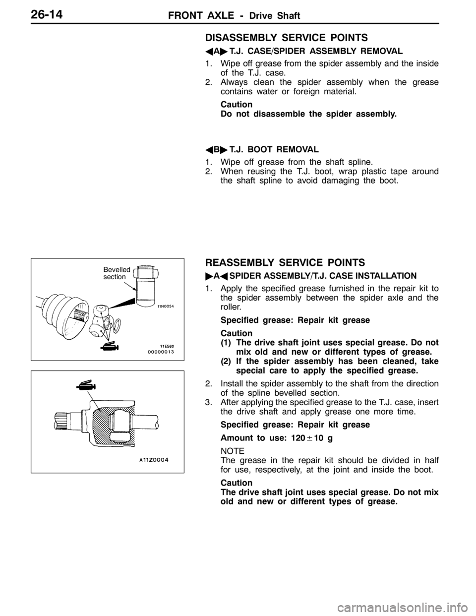
"AASPIDER ASSEMBLY/T.J. CASE INSTALLATION
1. Apply the specified grease furnished in the repair kit to
the spider assembly between the spider axle and the
roller.
Specified grease: Repair kit grease
Caution
(1) The drive shaft joint uses special grease. Do not
mix old and new or different types of grease.
(2) If the spider assembly has been cleaned, take
special care to apply the specified grease.
2. Install the spider assembly to the shaft from the direction
of the spline bevelled section.
3. After applying the specified grease to the T.J. case, insert
the drive shaft and apply grease one more time.
Specified grease: Repair kit grease
Amount to use: 120±10 g
NOTE
The grease in the repair kit should be divided in half
for use, respectively, at the joint and inside the boot.
Caution
The drive shaft joint uses special grease. Do not mix
old and new or different types of grease.Bevelled
section
Page 945 of 1449
FRONT AXLE -Drive Shaft26-17
10. Fill the inside of the B.J. boot with the specified amount
of the specified grease.
Specified grease: Repair kit grease
Amount to use: 110±10 g
Caution
The drive shaft joint uses special grease. Do not mix
old and new or different types of grease.
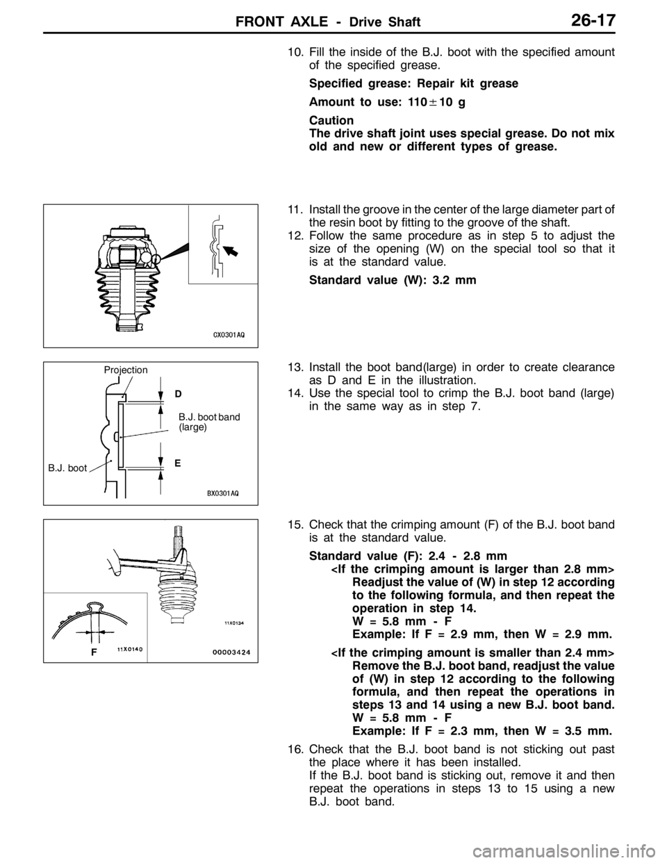
11. Install the groove in the center of the large diameter part of
the resin boot by fitting to the groove of the shaft.
12. Follow the same procedure as in step 5 to adjust the
size of the opening (W) on the special tool so that it
is at the standard value.
Standard value (W): 3.2 mm
13. Install the boot band(large) in order to create clearance
as D and E in the illustration.
14. Use the special tool to crimp the B.J. boot band (large)
in the same way as in step 7.
15. Check that the crimping amount (F) of the B.J. boot band
is at the standard value.
Standard value (F): 2.4 - 2.8 mm
Readjust the value of (W) in step 12 according
to the following formula, and then repeat the
operation in step 14.
W = 5.8 mm - F
Example: If F = 2.9 mm, then W = 2.9 mm.
Remove the B.J. boot band, readjust the value
of (W) in step 12 according to the following
formula, and then repeat the operations in
steps 13 and 14 using a new B.J. boot band.
W = 5.8 mm - F
Example: If F = 2.3 mm, then W = 3.5 mm.
16. Check that the B.J. boot band is not sticking out past
the place where it has been installed.
If the B.J. boot band is sticking out, remove it and then
repeat the operations in steps 13 to 15 using a new
B.J. boot band.
B.J. boot
Projection
B.J. boot band
(large)
D
E
F
Page 950 of 1449
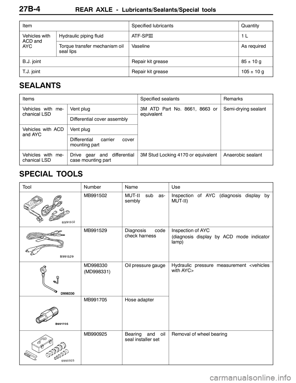
REAR AXLE -Lubricants/Sealants/Special tools27B-4
ItemQuantity Specified lubricants
Vehicles with
ACDand
Hydraulic piping fluidATF-SP�™1L
ACDand
AY CTorque transfer mechanism oil
seal lipsVaselineAs required
B.J. jointRepair kit grease85±10 g
T.J. jointRepair kit grease105±10 g
SEALANTS
ItemsSpecified sealantsRemarks
Vehicles with me-
chanicalLSD
Vent plug3M ATD Part No. 8661, 8663 or
equivalent
Semi-drying sealant
chanicalLSD
Differential cover assembly
equivalent
Vehicles with ACD
andAYC
Vent plug
andAYC
Differential carrier cover
mounting part
Vehicles with me-
chanical LSDDrive gear and differential
case mounting part3M Stud Locking 4170 or equivalentAnaerobic sealant
SPECIAL TOOLS
ToolNumberNameUse
MB991502MUT-IIsub as-
semblyInspection of AYC (diagnosis display by
MUT-II)
MB991529Diagnosis code
check harnessInspection of AYC
(diagnosis display by ACD mode indicator
lamp)
MD998330
(MD998331)Oil pressure gaugeHydraulic pressure measurement
with AYC>
MB991705Hose adapter
MB990925Bearing and oil
seal installer setRemoval of wheel bearing
Page 957 of 1449
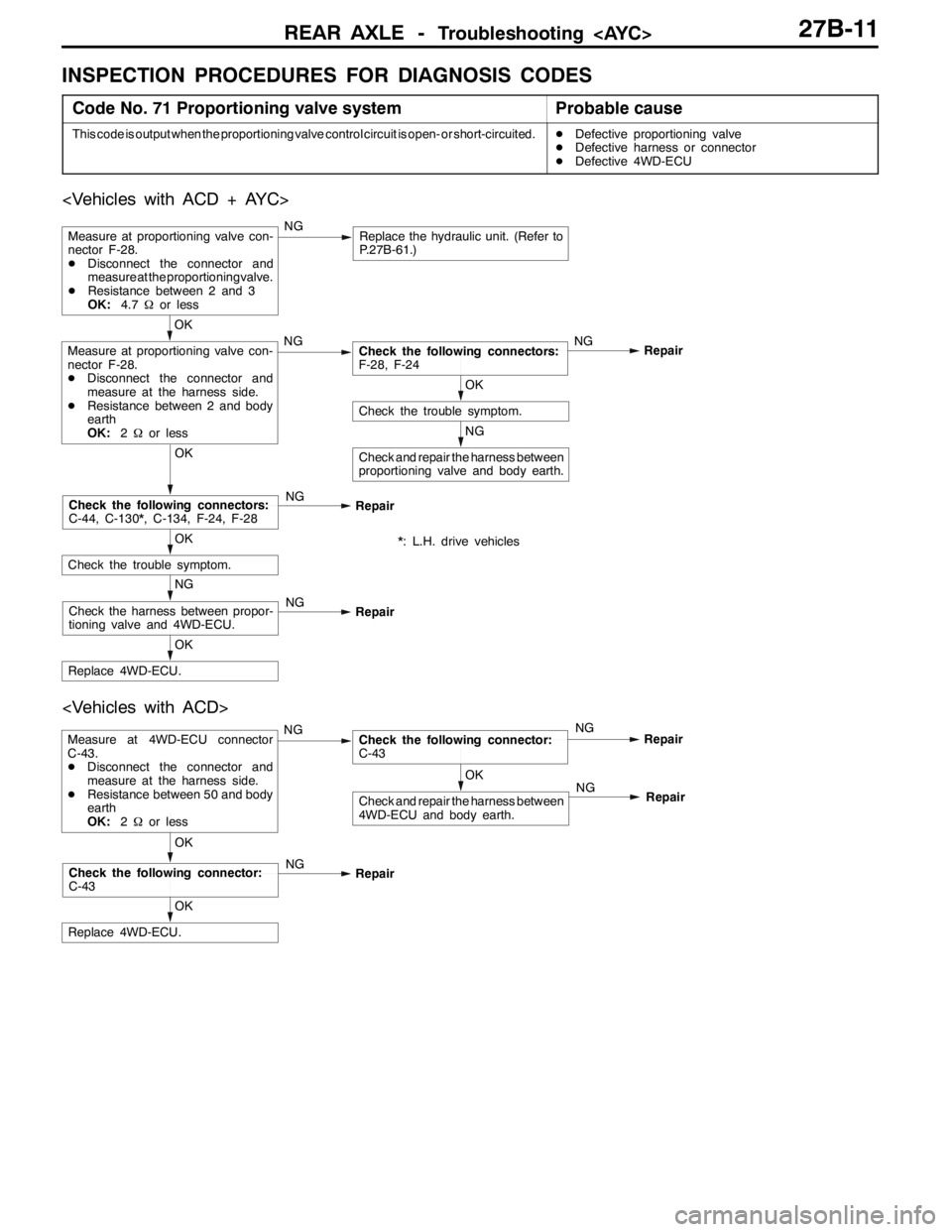
REAR AXLE-Troubleshooting 27B-11
INSPECTION PROCEDURES FOR DIAGNOSIS CODES
Code No. 71 Proportioning valve systemProbable cause
This code is output when the proportioning valve control circuit is open- or short-circuited.DDefective proportioning valve
DDefective harness or connector
DDefective 4WD-ECU
NG
Check and repair the harness between
proportioning valve and body earth.
OK
Check the trouble symptom.
OK
Measure at proportioning valve con-
nector F-28.
DDisconnect the connector and
measure at the harness side.
DResistance between 2 and body
earth
OK:2Ωor lessNGCheck the following connectors:
F-28, F-24NG
Repair
Measure at proportioning valve con-
nector F-28.
DDisconnect the connector and
measure at the proportioning valve.
DResistance between 2 and 3
OK:4.7Ωor lessNGReplace the hydraulic unit. (Refer to
P.27B-61.)
OK
Replace 4WD-ECU.
NG
Check the harness between propor-
tioning valve and 4WD-ECU.NG
Repair
OK
Check the trouble symptom.
OK
Check the following connectors:
C-44, C-130*, C-134, F-24, F-28NG
Repair
*: L.H. drive vehicles
OK
Replace 4WD-ECU.
OK
Check the following connector:
C-43NG
Repair
OK
Check and repair the harness between
4WD-ECU and body earth.
Measure at 4WD-ECU connector
C-43.
DDisconnect the connector and
measure at the harness side.
DResistance between 50 and body
earth
OK:2Ωor lessNGCheck the following connector:
C-43NG
Repair
NG
Repair
Page 958 of 1449
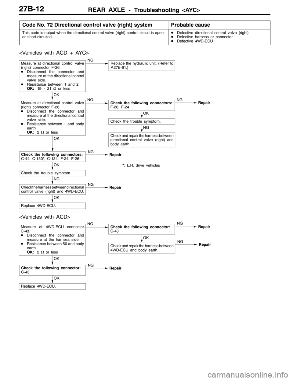
REAR AXLE -Troubleshooting 27B-12
Code No. 72 Directional control valve (right) systemProbable cause
This code is output when the directional control valve (right) control circuit is open-
or short-circuited.DDefective directional control valve (right)
DDefective harness or connector
DDefective 4WD-ECU
NG
Check and repair the harness between
directional control valve (right) and
body earth.
OK
Check the trouble symptom.
OK
Replace 4WD-ECU.
NG
Check the harness between directional
control valve (right) and 4WD-ECU.NG
Repair
OK
Check the trouble symptom.
OK
Check the following connectors:
C-44, C-130*, C-134, F-24, F-26NG
Repair
OK
Measure at directional control valve
(right) connector F-26.
DDisconnect the connector and
measure at the directional control
valve side.
DResistance between 1 and body
earth
OK:2Ωor lessNGCheck the following connectors:
F-26, F-24NG
Repair
Measure at directional control valve
(right) connector F-26.
DDisconnect the connector and
measure at the directional control
valve side.
DResistance between 1 and 2
OK:19 - 21Ωor lessNGReplace the hydraulic unit. (Refer to
P.27B-61.)
*: L.H. drive vehicles
OK
Check and repair the harness between
4WD-ECU and body earth.
Measure at 4WD-ECU connector
C-43.
DDisconnect the connector and
measure at the harness side.
DResistance between 50 and body
earth
OK:2Ωor lessNGCheck the following connector:
C-43NG
Repair
OK
Replace 4WD-ECU.
OK
Check the following connector:
C-43NG
RepairNG
Repair