2007 MITSUBISHI LANCER EVOLUTION to pair
[x] Cancel search: to pairPage 737 of 1449

ENGINE ELECTRICAL -Charging System16-5
(6) Reconnect the negative battery cable.
(7) Connect a tachometer or the MUT-II.
(Refer to GROUP 11 - On-vehicle Service.)
(8) Leave the hood open.
(9) Start the engine.
(10)With the engine running at 2,500 r/min, turn
the headlamps and other lamps on and off
to adjust the alternator load so that the value
displayed on the ammeter is slightly above 30
A.
Adjust the engine speed by gradually
decreasing it until the value displayed on the
ammeter is 30 A. Take a reading of the value
displayed on the voltmeter at this time.
Limit: max. 0.3 V
NOTE
When the alternator output is high and the value
displayed on the ammeter does not decrease
until 30 A, set the value to 40 A. Read the
value displayed on the voltmeter at this time.
When the value range is 40 A, the limit is max.
0.4 V.(11) If the value displayed on the voltmeter is above
the limit value, there is probably a malfunction
in the alternator output wire, so check the wiring
between the alternator “B” terminal and the
battery (+) terminal (including fusible link).
If a terminal is not sufficiently tight or if the
harness has become discolored due to
overheating, repair and then test again.
(12)After the test, run the engine at idle.
(13)Turn off all lamps and the ignition switch.
(14)Remove the tachometer or the MUT-II.
(15)Disconnect the negative battery cable.
(16)Disconnect the ammeter and voltmeter.
(17)Connect the alternator output wire to the
alternator “B” terminal.
(18)Connect the negative battery cable.
OUTPUT CURRENT TEST
Charging warning lampVoltmeter
Ammeter
Ignition switch
Alternator relayLoad
Battery
Engine-ECUAlternatorFR
L
S
G
+ -+-
B
Page 755 of 1449

ENGINE ELECTRICAL -Starting System16-23
REASSEMBLY SERVICE POINT
"AASTOP RING/SNAP RING INSTALLATION
Using a suitable pulling tool, pull overrunning clutch stop ring
over snap ring.
INSPECTION
COMMUTATOR CHECK
1. Place the armature in a pair of “V” blocks and check
the runout with a dial indicator.
Standard value: 0.05 mm
Limit: 0.1 mm
2. Measure the commutator outer diameter.
Standard value: 29.4 mm
Limit: 28.8 mm
3. Check the undercut depth between segments.
Standard value: 0.5 mm
Limit: 0.2 mm
BRUSH HOLDER CHECK
Confirm that the spring is activated when the brush is pressed
into the brush holder by hand.
Replace the brush holder if the spring is not activated.
Stop ringOverrunning
clutchStop ring
Snap ring
Undercut
Segment
Mica
Page 799 of 1449

CLUTCH -Clutch Control21A-9
DISASSEMBLY AND REASSEMBLY
CLUTCH MASTER CYLINDER
Caution
Do not disassemble piston assembly.
1
4 5
27
223
4
Grease: Rubber grease
Clutch fluid:
Brake fluid DOT3 or DOT4
Piston repair kit
13±2 N·m
12
3
6
8
4 5
8
Disassembly steps
1. Piston stopper ring
2. Piston assembly
"AA3. Push rod assembly
4. Boot5. Spring pin
6. Reservoir tank
7. Seal
8. Master cylinder body
INSTALLATION SERVICE POINT
"AAPUSH ROD ASSEMBLY INSTALLATION
Set the length of the push rod assembly to the shown
dimension to make the adjustment of clutch pedal easier.
104.3±0.5 mm
Page 816 of 1449
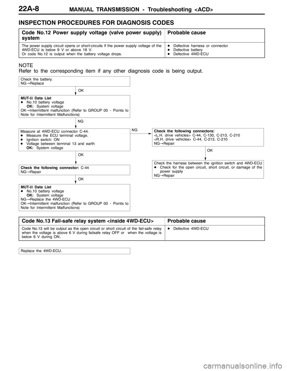
MANUAL TRANSMISSION - Troubleshooting
INSPECTION PROCEDURES FOR DIAGNOSIS CODES
Code No.12 Power supply voltage (valve power supply)
systemProbable cause
The power supply circuit opens or short-circuits if the power supply voltage of the
4WD-ECU is below 9 V or above 18 V.
Or code No.12 is output when the battery voltage drops.DDefective harness or connector
DDefective battery
DDefective 4WD-ECU
NOTE
Refer to the corresponding item if any other diagnosis code is being output.
OKOK
NG
NG
OK
Check the battery.
NG→Replace
Measure at 4WD-ECU connector C-44.
DMeasure the ECU terminal voltage.
DIgnition switch: ON
DVoltage between terminal 13 and earth
OK:System voltageCheck the following connectors:
NG→Repair
MUT-IIData List
DNo.10 battery voltage
OK:System voltage
OK→Intermittent malfunction (Refer to GROUP 00 - Points to
Note for Intermittent Malfunctions)
OK
Check the following connector:C-44
NG→Repair
MUT-IIData List
DNo.10 battery voltage
OK:System voltage
NG→Replace the 4WD-ECU
OK→Intermittent malfunction (Refer to GROUP 00 - Points to
Note for Intermittent Malfunctions)
Check the harness between the ignition switch and 4WD-ECU
DCheck for the open circuit, short circuit, or damage of the
power supply
NG→Repair
Code No.13 Fail-safe relay system
Code No.13 will be output as the open circuit or short circuit of the fail-safe relay
when the voltage is above 6 V during failsafe relay OFF or when the voltage is
below 6 V during ON.DDefective 4WD-ECU
Replace the 4WD-ECU.
Page 817 of 1449
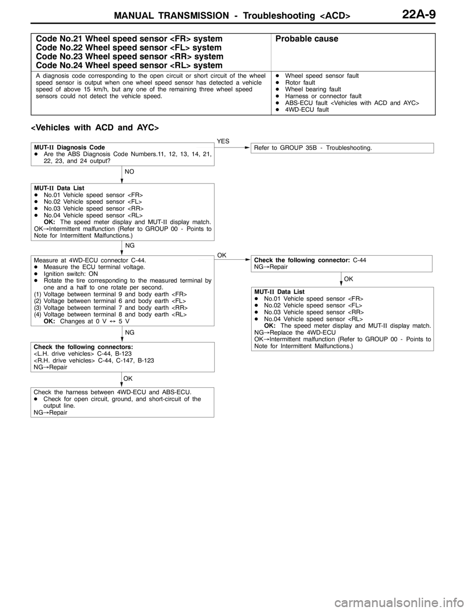
MANUAL TRANSMISSION - Troubleshooting
Code No.21 Wheel speed sensor
Code No.22 Wheel speed sensor
Code No.23 Wheel speed sensor
Code No.24 Wheel speed sensor
A diagnosis code corresponding to the open circuit or short circuit of the wheel
speed sensor is output when one wheel speed sensor has detected a vehicle
speed of above 15 km/h, but any one of the remaining three wheel speed
sensors could not detect the vehicle speed.DWheel speed sensor fault
DRotor fault
DWheel bearing fault
DHarness or connector fault
DABS-ECU fault
D4WD-ECU fault
OKNGYES
NO
OK
Measure at 4WD-ECU connector C-44.
DMeasure the ECU terminal voltage.
DIgnition switch: ON
DRotate the tire corresponding to the measured terminal by
one and a half to one rotate per second.
(1) Voltage between terminal 9 and body earth
(2) Voltage between terminal 6 and body earth
(3) Voltage between terminal 7 and body earth
(4) Voltage between terminal 8 and body earth
OK:Changes at 0 V↔5VCheck the following connector:C-44
NG→Repair
Check the following connectors:
NG→Repair
MUT-IIDiagnosis Code
DAre the ABS Diagnosis Code Numbers.11, 12, 13, 14, 21,
22, 23, and 24 output?Refer to GROUP 35B - Troubleshooting.
NG
MUT-IIData List
DNo.01 Vehicle speed sensor
DNo.02 Vehicle speed sensor
DNo.03 Vehicle speed sensor
DNo.04 Vehicle speed sensor
OK:The speed meter display and MUT-IIdisplay match.
OK→Intermittent malfunction (Refer to GROUP 00 - Points to
Note for Intermittent Malfunctions.)
OK
Check the harness between 4WD-ECU and ABS-ECU.
DCheck for open circuit, ground, and short-circuit of the
output line.
NG→Repair
MUT-IIData List
DNo.01 Vehicle speed sensor
DNo.02 Vehicle speed sensor
DNo.03 Vehicle speed sensor
DNo.04 Vehicle speed sensor
OK:The speed meter display and MUT-IIdisplay match.
NG→Replace the 4WD-ECU
OK→Intermittent malfunction (Refer to GROUP 00 - Points to
Note for Intermittent Malfunctions.)
Page 818 of 1449
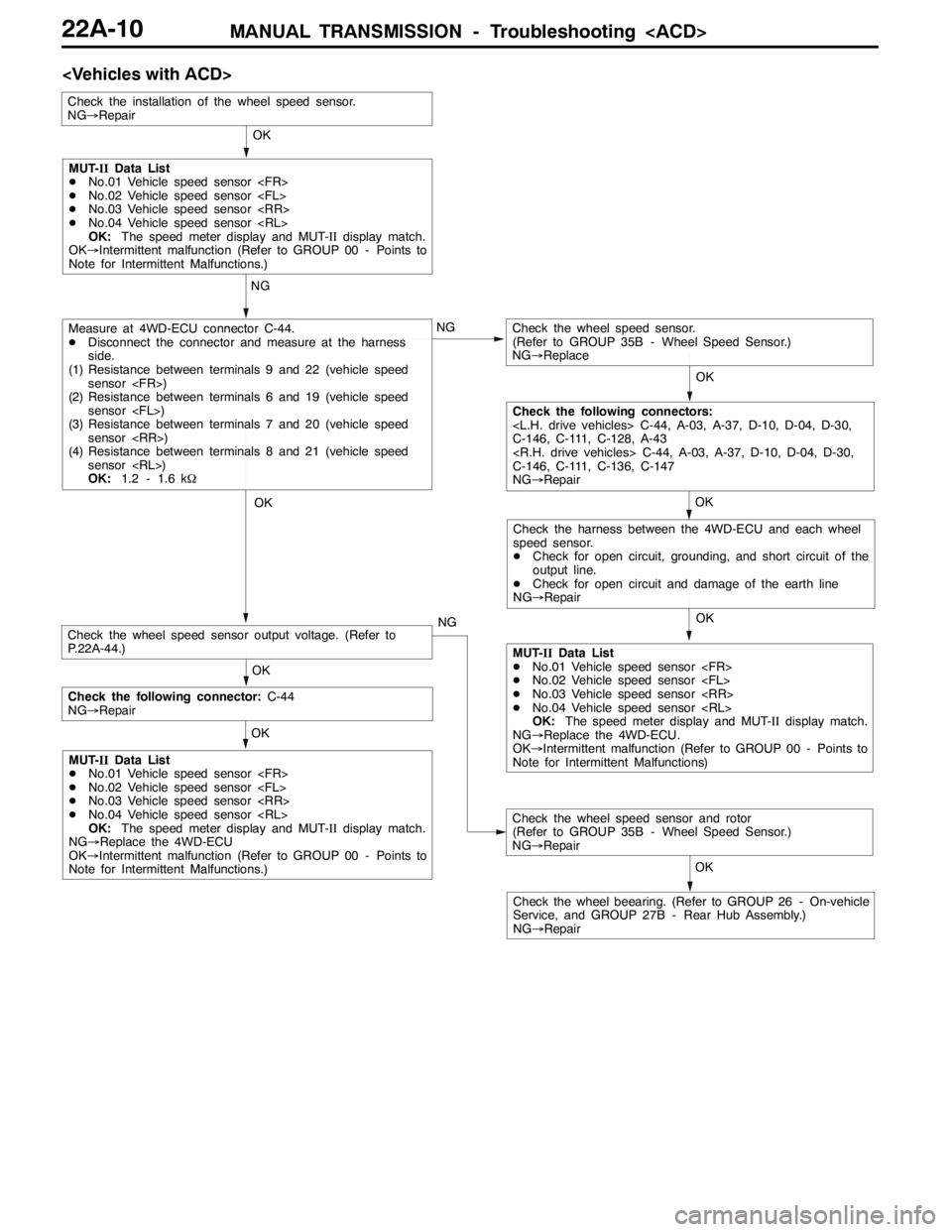
MANUAL TRANSMISSION - Troubleshooting
OK OK NG
OK NG
OK OK
OK
NG
Measure at 4WD-ECU connector C-44.
DDisconnect the connector and measure at the harness
side.
(1) Resistance between terminals 9 and 22 (vehicle speed
sensor
(2) Resistance between terminals 6 and 19 (vehicle speed
sensor
(3) Resistance between terminals 7 and 20 (vehicle speed
sensor
(4) Resistance between terminals 8 and 21 (vehicle speed
sensor
OK:1.2 - 1.6 kΩCheck the wheel speed sensor.
(Refer to GROUP 35B - Wheel Speed Sensor.)
NG→Replace
Check the installation of the wheel speed sensor.
NG→Repair
Check the wheel speed sensor and rotor
(Refer to GROUP 35B - Wheel Speed Sensor.)
NG→Repair
Check the wheel beearing. (Refer to GROUP 26 - On-vehicle
Service, and GROUP 27B - Rear Hub Assembly.)
NG→RepairOK
MUT-IIData List
DNo.01 Vehicle speed sensor
DNo.02 Vehicle speed sensor
DNo.03 Vehicle speed sensor
DNo.04 Vehicle speed sensor
OK:The speed meter display and MUT-IIdisplay match.
OK→Intermittent malfunction (Refer to GROUP 00 - Points to
Note for Intermittent Malfunctions.)
Check the following connectors:
C-146, C-111, C-128, A-43
C-146, C-111, C-136, C-147
NG→Repair
Check the harness between the 4WD-ECU and each wheel
speed sensor.
DCheck for open circuit, grounding, and short circuit of the
output line.
DCheck for open circuit and damage of the earth line
NG→Repair
MUT-IIData List
DNo.01 Vehicle speed sensor
DNo.02 Vehicle speed sensor
DNo.03 Vehicle speed sensor
DNo.04 Vehicle speed sensor
OK:The speed meter display and MUT-IIdisplay match.
NG→Replace the 4WD-ECU.
OK→Intermittent malfunction (Refer to GROUP 00 - Points to
Note for Intermittent Malfunctions) OK
Check the following connector:C-44
NG→Repair
MUT-IIData List
DNo.01 Vehicle speed sensor
DNo.02 Vehicle speed sensor
DNo.03 Vehicle speed sensor
DNo.04 Vehicle speed sensor
OK:The speed meter display and MUT-IIdisplay match.
NG→Replace the 4WD-ECU
OK→Intermittent malfunction (Refer to GROUP 00 - Points to
Note for Intermittent Malfunctions.)
Check the wheel speed sensor output voltage. (Refer to
P.22A-44.)
Page 819 of 1449
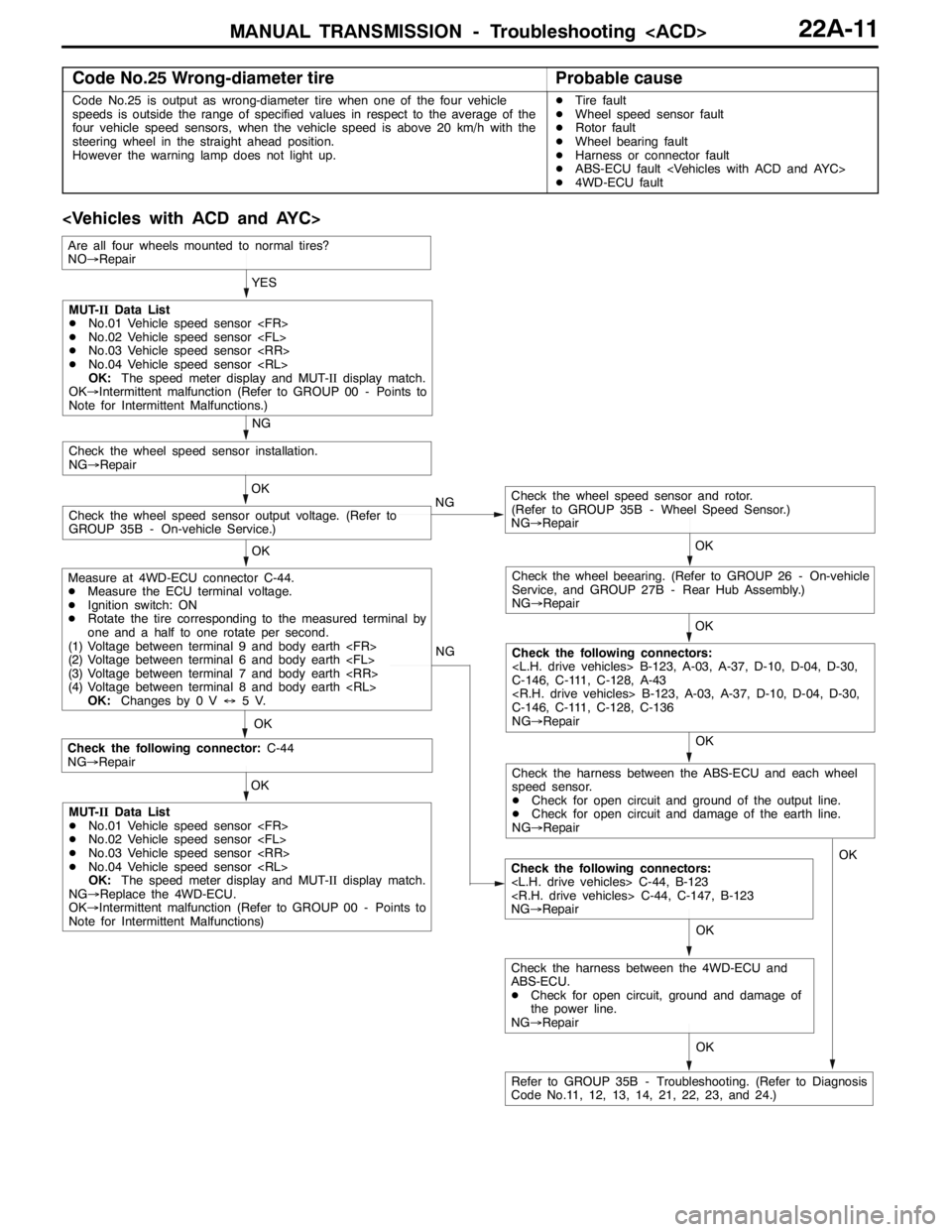
MANUAL TRANSMISSION - Troubleshooting
Code No.25 Wrong-diameter tireProbable cause
Code No.25 is output as wrong-diameter tire when one of the four vehicle
speeds is outside the range of specified values in respect to the average of the
four vehicle speed sensors, when the vehicle speed is above 20 km/h with the
steering wheel in the straight ahead position.
However the warning lamp does not light up.DTire fault
DWheel speed sensor fault
DRotor fault
DWheel bearing fault
DHarness or connector fault
DABS-ECU fault
D4WD-ECU fault
OK NG
OK
Check the following connector:C-44
NG→Repair
Check the following connectors:
NG→Repair OKYES
OK
OK
Check the wheel speed sensor and rotor.
(Refer to GROUP 35B - Wheel Speed Sensor.)
NG→Repair
Check the wheel speed sensor output voltage. (Refer to
GROUP 35B - On-vehicle Service.)OK
Check the wheel speed sensor installation.
NG→Repair
NG
OK
Check the wheel beearing. (Refer to GROUP 26 - On-vehicle
Service, and GROUP 27B - Rear Hub Assembly.)
NG→Repair
OK
Check the following connectors:
C-146, C-111, C-128, A-43
C-146, C-111, C-128, C-136
NG→Repair NG
MUT-IIData List
DNo.01 Vehicle speed sensor
DNo.02 Vehicle speed sensor
DNo.03 Vehicle speed sensor
DNo.04 Vehicle speed sensor
OK:The speed meter display and MUT-IIdisplay match.
OK→Intermittent malfunction (Refer to GROUP 00 - Points to
Note for Intermittent Malfunctions.)
Measure at 4WD-ECU connector C-44.
DMeasure the ECU terminal voltage.
DIgnition switch: ON
DRotate the tire corresponding to the measured terminal by
one and a half to one rotate per second.
(1) Voltage between terminal 9 and body earth
(2) Voltage between terminal 6 and body earth
(3) Voltage between terminal 7 and body earth
(4) Voltage between terminal 8 and body earth
OK:Changes by 0 V↔5V.
MUT-IIData List
DNo.01 Vehicle speed sensor
DNo.02 Vehicle speed sensor
DNo.03 Vehicle speed sensor
DNo.04 Vehicle speed sensor
OK:The speed meter display and MUT-IIdisplay match.
NG→Replace the 4WD-ECU.
OK→Intermittent malfunction (Refer to GROUP 00 - Points to
Note for Intermittent Malfunctions)
Refer to GROUP 35B - Troubleshooting. (Refer to Diagnosis
Code No.11, 12, 13, 14, 21, 22, 23, and 24.)
Are all four wheels mounted to normal tires?
NO→Repair
Check the harness between the ABS-ECU and each wheel
speed sensor.
DCheck for open circuit and ground of the output line.
DCheck for open circuit and damage of the earth line.
NG→Repair
OK
Check the harness between the 4WD-ECU and
ABS-ECU.
DCheck for open circuit, ground and damage of
the power line.
NG→RepairOK
Page 820 of 1449
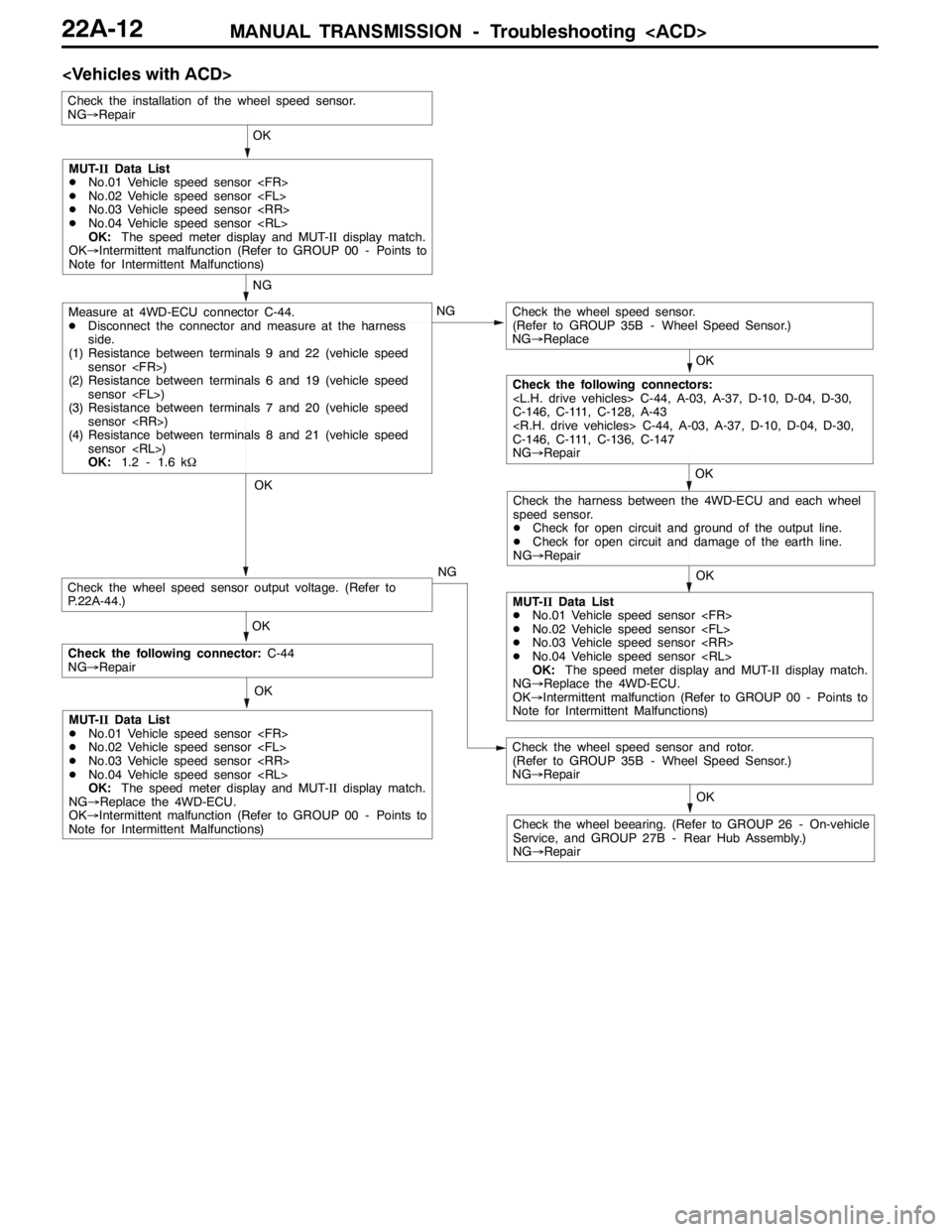
MANUAL TRANSMISSION - Troubleshooting
OK OK NG
OK NG
OK OK
OK
NG
Measure at 4WD-ECU connector C-44.
DDisconnect the connector and measure at the harness
side.
(1) Resistance between terminals 9 and 22 (vehicle speed
sensor
(2) Resistance between terminals 6 and 19 (vehicle speed
sensor
(3) Resistance between terminals 7 and 20 (vehicle speed
sensor
(4) Resistance between terminals 8 and 21 (vehicle speed
sensor
OK:1.2 - 1.6 kΩCheck the wheel speed sensor.
(Refer to GROUP 35B - Wheel Speed Sensor.)
NG→Replace
Check the installation of the wheel speed sensor.
NG→Repair
Check the wheel speed sensor and rotor.
(Refer to GROUP 35B - Wheel Speed Sensor.)
NG→Repair
Check the wheel beearing. (Refer to GROUP 26 - On-vehicle
Service, and GROUP 27B - Rear Hub Assembly.)
NG→RepairOK
MUT-IIData List
DNo.01 Vehicle speed sensor
DNo.02 Vehicle speed sensor
DNo.03 Vehicle speed sensor
DNo.04 Vehicle speed sensor
OK:The speed meter display and MUT-IIdisplay match.
OK→Intermittent malfunction (Refer to GROUP 00 - Points to
Note for Intermittent Malfunctions)
Check the following connectors:
C-146, C-111, C-128, A-43
C-146, C-111, C-136, C-147
NG→Repair
Check the harness between the 4WD-ECU and each wheel
speed sensor.
DCheck for open circuit and ground of the output line.
DCheck for open circuit and damage of the earth line.
NG→Repair
MUT-IIData List
DNo.01 Vehicle speed sensor
DNo.02 Vehicle speed sensor
DNo.03 Vehicle speed sensor
DNo.04 Vehicle speed sensor
OK:The speed meter display and MUT-IIdisplay match.
NG→Replace the 4WD-ECU.
OK→Intermittent malfunction (Refer to GROUP 00 - Points to
Note for Intermittent Malfunctions) OK
Check the following connector:C-44
NG→Repair
MUT-IIData List
DNo.01 Vehicle speed sensor
DNo.02 Vehicle speed sensor
DNo.03 Vehicle speed sensor
DNo.04 Vehicle speed sensor
OK:The speed meter display and MUT-IIdisplay match.
NG→Replace the 4WD-ECU.
OK→Intermittent malfunction (Refer to GROUP 00 - Points to
Note for Intermittent Malfunctions)
Check the wheel speed sensor output voltage. (Refer to
P.22A-44.)