2007 MITSUBISHI LANCER EVOLUTION to pair
[x] Cancel search: to pairPage 632 of 1449

MPI -Troubleshooting13A-100
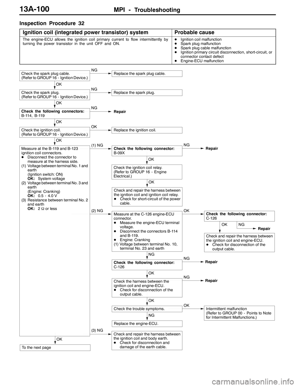
Inspection Procedure 32
Ignition coil (integrated power transistor) system
Probable cause
The engine-ECU allows the ignition coil primary current to flow intermittently by
turning the power transistor in the unit OFF and ON.DIgnition coil malfunction
DSpark plug malfunction
DSpark plug cable malfunction
DIgnition primary circuit disconnection, short-circuit, or
connector contact defect
DEngine-ECU malfunction
OK
Check and repair the harness between
the ignition coil and engine-ECU.
DCheck for disconnection of the
output cable.
OK
To the next page
(3) NGCheck and repair the harness between
the ignition coil and body earth.
DCheck for disconnection and
damage of the earth cable.
NG
Replace the engine-ECU.
OK
Check the trouble symptoms.OKIntermittent malfunction
(Refer to GROUP 00 - Points to Note
for Intermittent Malfunctions.) NG
OK
Check the harness between the
ignition coil and engine-ECU.
DCheck for disconnection of the
output cable.Repair NG
NG
Check the following connector:
C-126Repair
(2) NGMeasure at the C-126 engine-ECU
connector.
DMeasure the engine-ECU terminal
voltage.
DDisconnect the connectors B-114
and B-119.
DEngine: Cranking
(1) Voltage between terminal No. 10,
terminal No. 23 and earthOKCheck the following connector:
C-126
OK
Check and repair the harness between
the ignition coil and ignition coil relay.
DCheck for short-circuit of the power
cable.
OK
Check the ignition coil relay.
(Refer to GROUP 16 - Engine
Electrical.)
OK
Measure at the B-119 and B-123
ignition coil connectors.
DDisconnect the connector to
measure at the harness side.
(1) Voltage between terminal No. 1 and
earth
(Ignition switch: ON)
OK:System voltage
(2) Voltage between terminal No. 3 and
earth
(Engine: Cranking)
OK:0.5 - 4.0 V
(3) Resistance between terminal No. 2
and earth
OK:2Ωor less(1) NGCheck the following connector:
B-09XNG
Repair
OK
Check the ignition coil.
(Refer to GROUP 16 - Ignition Device.)OKReplace the ignition coil.
OK
Check the following connectors:
B-114, B-119NG
Repair
OK
Check the spark plug.
(Refer to GROUP 16 - Ignition Device.)NGReplace the spark plug.
Check the spark plug cable.
(Refer to GROUP 16 - Ignition Device.)NGReplace the spark plug cable.
NG
Repair
Page 633 of 1449

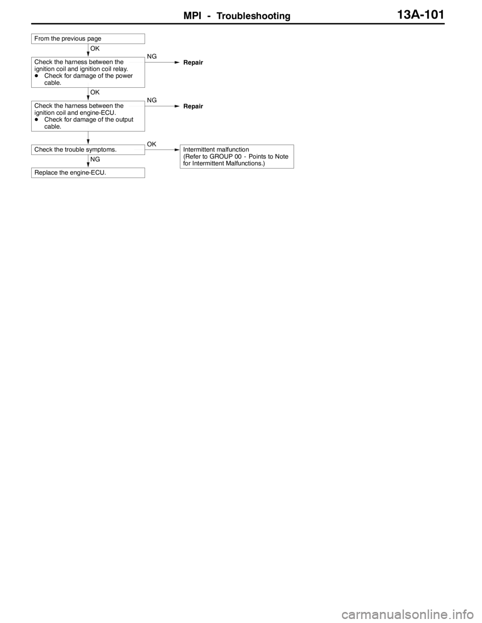
MPI -Troubleshooting13A-101
NG
Replace the engine-ECU.
Check the trouble symptoms.OKIntermittent malfunction
(Refer to GROUP 00 - Points to Note
for Intermittent Malfunctions.)
OK
Check the harness between the
ignition coil and engine-ECU.
DCheck for damage of the output
cable.NG
Repair
OK
Check the harness between the
ignition coil and ignition coil relay.
DCheck for damage of the power
cable.NG
Repair
From the previous page
Page 640 of 1449

MPI -Troubleshooting13A-108
Item
No.Reference
page Inspection
procedure
No. Normal condition Inspection contents Drive contents Inspection
item
21Fan
controllerRadiator fan
motor is
driven.Ignition switch: “ON”Fan motor rotates
at high speed.Procedure
No. 2413A-87
36Secondary
air control
solenoid
valveSolenoid valve
turns from
OFF to ON.Ignition switch: “ON”Sound of opera-
tion can be heard
when solenoid
valve is driven.Procedure
No. 2913A-96
37Condenser
fan (HI)Condensor
fan motor is
driven.Ignition switch: “ON”Fan motor rotates
at high speed.Procedure
No. 2513A-89
38Condenser
fan (LOW)Second air
control
solenoid valveIgnition switch: “ON”Fan motor rotates
at low speed.
CHECK AT THE ENGINE-ECU TERMINALS
TERMINAL VOLTAGE CHECK CHART
1. Connect a needle-nosed wire probe (test harness:
MB991223 or paper clip) to a voltmeter probe.
2. Insert the needle-nosed wire probe into each of the
engine-ECU connector terminals from the wire side, and
measure the voltage while referring to the check chart.
NOTE
(1) Make the voltage measurement with the engine-ECU
connectors connected.
(2) You may find it convenient to pull out the engine-ECU
to make it easier to reach the connector terminals.
(3) The checks can be carried out off the order given
in the chart.
Caution
Short-circuiting the positive (+) probe between a
connector terminal and earth could damage the
vehicle wiring, the sensor, engine-ECU or all of them.
Be careful to prevent this!
3. If voltmeter shows any division from standard value, check
the corresponding sensor, actuator and related electrical
wiring, then repair or replace.
4. After repair or replacement, recheck with the voltmeter
to confirm that the repair has corrected the problem.
Needle-nosed wire probe
Page 646 of 1449

MPI -Troubleshooting13A-114
CHECK CHART FOR RESISTANCE AND CONTINUITY
BETWEEN TERMINALS
1. Turn the ignition switch to “LOCK” (OFF) position.
2. Disconnect the engine-ECU connector.
3. Measure the resistance and check for continuity between
the terminals of the engine-ECU harness-side connector
while referring to the check chart.
NOTE
(1) When measuring resistance and checking continuity,
a harness for checking contact pin pressure should
be used instead of inserting a test probe.
(2) Checking need not be carried out in the order given
in the chart.
Caution
If the terminals that should be checked are mistaken,
or if connector terminals are not correctly shorted
to earth, damage may be caused to the vehicle wiring,
sensors, engine-ECU and/or ohmmeter.
Be careful to prevent this!
4. If the ohmmeter shows any deviation from the standard
value, check the corresponding sensor, actuator and
related electrical wiring, and then repair or replace.
5. After repair or replacement, recheck with the ohmmeter
to confirm that the repair or replacement has corrected
the problem.
Engine-ECU Harness Side Connector Terminal Arrangement
Terminal No.Inspection itemNormal condition (Check condition)
1-12No. 1 injector2-3Ω(at 20_C)
14 - 12No. 2 injector
2-12No. 3 injector
15 - 12No. 4 injector
Page 662 of 1449

MPI -On-vehicle Service13A-130
14. If any of fuel pressure measured in steps 10 to 13 is out of
specification, troubleshoot and repair according to the
table below.
SymptomProbable causeRemedy
DFuel pressure too low
DFuelpressuredropsafterracing
Clogged fuel filterReplace fuel filter
DFuelpressuredrops after racing
DNo fuel pressure in fuel return
hose
Fuel leaking to return side due to poor
fuel regulator valve seating or settled
springReplace fuel pressure regulator
Low fuel pump delivery pressureReplace fuel pump
Fuel pressure too highBinding valve in fuel pressure
regulatorReplace fuel pressure regulator
Clogged fuel return hose or pipeClean or replace hose or pipe
Same fuel pressure when vacuum
hose is connected and when
disconnected
Damaged vacuum hose or clogged
nippleReplace vacuum hose or clean nipple
disconnectedFuel pressure control system
malfunctionCheck the fuel pressure control
system
15. Stop the engine and check change of fuel pressure gauge
reading. Normal if the reading does not drop within 2
minutes. If it does, observe the rate of drop and
troubleshoot and repair according to the table below.
SymptomProbable causeRemedy
Fuel pressure drops gradually after
engineisstopped
Leaky injectorReplace injector
engineisstopped
Leaky fuel regulator valve seatReplace fuel pressure regulator
Fuel pressure drops sharply
immediately after engine is stoppedCheck valve in fuel pump is held openReplace fuel pump
16. Release residual pressure from the fuel pipe line.
(Refer to P.13A-125.)
17. Remove the fuel pressure gauge and special tool from
the delivery pipe.
Caution
Cover the hose connection with rags to prevent splash
of fuel that could be caused by some residual pressure
in the fuel pipe line.
18. Replace the O-ring at the end of the fuel high pressure
hose with a new one. Furthermore, apply engine oil to
the new O-ring before replacement.
19. Fit the fuel high pressure hose over the delivery pipe
and tighten the bolt to specified torque.
Tightening torque: 5.0±1.0 N·m
20. Check for any fuel leaks by following the procedure in
step 7.
21. Disconnect the MUT-II.
Page 692 of 1449

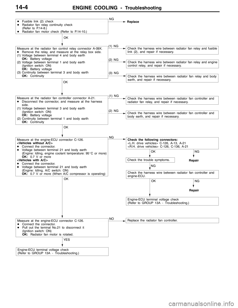
ENGINE COOLING -Troubleshooting14-4
Measure at the engine-ECU connector C-126.
DConnect the connector.
DPull out the teminal No.21 to disconnect it
(Ignition switch: ON)
OK:Radiator fan motor is rotated.
YES
Engine-ECU terminal voltage check
(Refer to GROUP 13A - Troubleshooting.)NO
Replace the radiator fan controller.
NG
Repair
OK
NG
Repair
OK
Check the harness wire between radiator fan controller and
engine-ECU.
Measure at the engine-ECU connector C-126.
DConnect the connector.
DVoltage between terminal 21 and body earth
(Engine: Idling, engine coolant temperature: 95_C or more)
OK:0.7 V or more
DConnect the connector.
DVoltage between terminal 21 and body earth
(Engine: Idling, A/C switch: ON)
OK:0.7 V or more (When A/C compressor is operating)NG
(2) NGCheck the harness wire between radiator fan controller and
body earth, and repair if necessary.
OK
Measure at the radiator fan controller connector A-21.
DDisconnect the connector, and measure at the harness
side.
(1) Voltage between terminal 3 and body earth
(Ignition switch: ON)
OK:Battery voltage
(2) Continuity between terminal 1 and body earth
OK:Continuity(1) NGCheck the harness wire between radiator fan controller and
radiator fan relay, and repair if necessary.
(3) NGCheck the harness wire between radiator fan relay and body
earth, and repair if necessary.
(2) NGCheck the harness wire between radiator fan relay and engine
control relay, and repair if necessary.
OK
Measure at the radiator fan control relay connector A-09X.
DRemove the relay, and measure at the relay box side.
(1) Voltage between terminal 4 and body earth
OK:Battery voltage
(2) Voltage between terminal 1 and body earth
(Ignition switch: ON)
OK:Battery voltage
(3) Continuity between terminal 3 and body earth
OK:Continuity(1) NGCheck the harness wire between radiator fan relay and fusible
link (2), and repair if necessary.
DFusible link (2) check
DRadiator fan relay continuity check
(Refer to P.14-8.)
DRadiator fan motor check (Refer to P.14-10.)NG
Replace
OK
OK
Engine-ECU terminal voltage check
(Refer to GROUP 13A - Troubleshooting.)
Check the following connectors:
NG
Check the trouble symptoms.
Page 693 of 1449

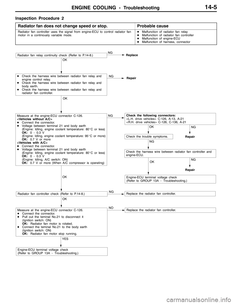
ENGINE COOLING -Troubleshooting14-5
Inspection Procedure 2
Radiator fan does not change speed or stop.
Probable cause
Radiator fan controller uses the signal from engine-ECU to control radiator fan
motor in a continously variable mode.DMalfunction of radiator fan relay
DMalfunction of radiator fan controller
DMalfunction of engine-ECU
DMalfunction of harness, connector
Measure at the engine-ECU connector C-126.
DConnect the connector.
DPull out the teminal No.21 to disconnect it
(Ignition switch: ON)
OK:Radiator fan motor is rotated.
DConnect the teminal No.21 to the body earth
(Ignition switch: ON)
OK:Radiator fan motor stop running.
YES
Engine-ECU terminal voltage check
(Refer to GROUP 13A - Troubleshooting.)NO
Replace the radiator fan controller.
OK
Radiator fan controller check (Refer to P.14-8.)NGReplace the radiator fan controller.
OK
Measure at the engine-ECU connector C-126.
DConnect the connector.
DVoltage between terminal 21 and body earth
(Engine: Idling, engine coolant temperature: 80_C or less)
OK:0 - 0.3 V
(Engine: Idling, engine coolant temperature: 95_C or more)
OK:0.7 V or more
DConnect the connector.
DVoltage between terminal 21 and body earth
(Engine: Idling, engine coolant temperature: 80_C or less)
OK:0 - 0.3 V
(Engine: Idling, A/C switch: ON)
OK:0.7 V or more (When A/C compressor is operating)NG
OK
DCheck the harness wire between radiator fan relay and
engine control relay.
DCheck the harness wire between radiator fan relay and
body earth.
DCheck the harness wire between radiator fan relay and
radiator fan controller.NG
Repair
NG
Replace
OK
OK
OK
Check the following connectors:
NG
Engine-ECU terminal voltage check
(Refer to GROUP 13A - Troubleshooting.)
Check the trouble symptoms.
NG
NG
Repair
Repair
Radiator fan relay continuity check (Refer to P.14-8.)
Check the harness wire between radiator fan controller and
engine-ECU.
Page 694 of 1449

ENGINE COOLING -On-vehicle Service14-6
ON-VEHICLE SERVICE
ENGINE COOLANT LEAK CHECKING
1. Confirm that the coolant level is up to the filler neck.
Install a radiator cap tester and apply 160 kPa pressure,
and then check for leakage from the radiator hose or
connections.
Caution
(1) Be sure to completely clean away any moisture
from the places checked.
(2) When the tester is taken out, be careful not to
spill any coolant from it.
(3) Be careful, when installing and removing the tester
and when testing, not to deform the filler neck
of the radiator.
2. If there is leakage, repair or replace the appropriate part.
RADIATOR CAP OPENING PRESSURE CHECK
1. Use a cap adapter to attach the cap to the tester.
2. Increase the pressure until the indicator of the gauge
stops moving.
Limit: 83 kPa
Standard value: 93 - 123 kPa
3. Replace the radiator cap if the reading does not remain
at or above the limit.
NOTE
Be sure that the cap is clean before testing, since rust
or other foreign material on the cap seal will cause an
improper indication.
ENGINE COOLANT REPLACEMENT
1. Remove the under cover.
(Refer to GROUP 51 - Front Bumper.)
2. Drain the engine coolant by removing the drain plug and
then the radiator cap.
Cap adapter
Adapter
Cap adapter