Page 1 of 1449

00
11
12
13
14
15
16
17
21
22
25
26
27
31
32
33
34
35
36
37
42
51
52
54
55
General........................
Engine .........................
Engine Lubrication .............
Fuel ...........................
Engine Cooling .................
Intake and Exhaust ............
Engine Electrical ...............
Engine and Emission Control ....
Clutch .........................
Manual Transmission ...........
Propeller Shaft .................
Front Axle ......................
Rear Axle ......................
Wheel and Tyre .................
Power Plant Mount ..............
Front Suspension ...............
Rear Suspension ...............
Service Brakes .................
Parking Brakes .................
Steering ........................
Body ...........................
Exterior ........................
Chassis Electrical ..............
Electrical Wiring ................
Body Repair ....................
WORKSHOP
MANUAL
FOREWORD
This Workshop Manual contains procedures for
service mechanics, including removal, disassembly,
inspection, adjustment, reassembly and
installation. Use the following manuals in
combination with this manual as required.
TECHNICAL INFORMATION MANUAL N0104CT9A
All information, illustrations and product
descriptions contained in this manual are current
as at the time of publication. We, however, reserve
the right to make changes at any time without prior
notice or obligation.
The EVOLUTION-VII is sold exclusively through
RALLIART Inc. Since the EVOLUTION-VII is a
rally-based model, it will not be warranted and will
not be homologated for general production.
Therefore, any service matters on the
EVOLUTION-VII should be inquired to RALLIART
Inc. as usual.
EMitsubishi Motors Corporation May 2001
Interior and Supplemental
Restraint System (SRS) ........
Heater, Air Conditioner and
Ventilation .....................
Page 23 of 1449
BODY CONSTRUCTION -Silencer Application LocationsA-21
SILENCER APPLICATION LOCATIONS
Silencers (MD - 12 and melting sheets) are attached to the top of the floor to reduce vibration and insulate
against the heat from exhaust gas.
NOTE
MD - 12 is a high performance sheet composed of asphalt applied with mica and thermosetting resin for
improving anti-vibration performance.
: 1.6 mm thick melting sheet
: 3.2 mm thick melting sheet (Place two 1.6 mm melting sheets one on top of another.)
: 4.0 mm thick MD - 12 (Place three 1.6 mm melting sheets one on top of another.)
NOTE
The number in the parentheses indicates the number of melting sheet
used for repair.
Page 47 of 1449
WELDED PANEL REPLACEMENT -Headlamp SupportC-3
HEADLAMP SUPPORT
SymbolOperation description
Spot welding
MIG plug welding (J: indicates two panels to be
welded
Y: indicates three panels to be welded)
MIG spot welding
MIG arc welding (continuous)
Braze welding
Anti-corrosion agent application locations
(Use access holes to apply liberally to butt-welded
joints.)
A
A
BB
B
REPAIR WELDS
(Right side)
Page 48 of 1449
WELDED PANEL REPLACEMENT -Fender ShieldC-4
FENDER SHIELD
SymbolOperation description
Spot welding
MIG plug welding (J: indicates two panels to be
welded
Y: indicates three panels to be welded)
MIG spot welding
MIG arc welding (continuous)
Braze welding
Anti-corrosion agent application locations
(Use access holes to apply liberally to butt-welded
joints.)
A
A
F
REPAIR WELDS
NOTE
For the weld points for the headlamp support, refer to P.C-3 Headlamp Support.
Page 51 of 1449
WELDED PANEL REPLACEMENT -Front PillarC-7
FRONT PILLAR
SymbolOperation description
Spot welding
MIG plug welding (J: indicates two panels to be
welded
Y: indicates three panels to be welded)
MIG spot welding
MIG arc welding (continuous)
Braze welding
Anti-corrosion agent application locations
(Use access holes to apply liberally to butt-welded
joints.)
2point
passenger’s
side
B
C B
C
180±20mm
60±10 mm
A
A
D
D
REPAIR WELDS
Foam acoustic material
(With the upper frame extension outer removed)RS-II
Caution
Do not use heat at areas using foam material as the foam material may burn.
Page 52 of 1449

WELDED PANEL REPLACEMENT -Front PillarC-8
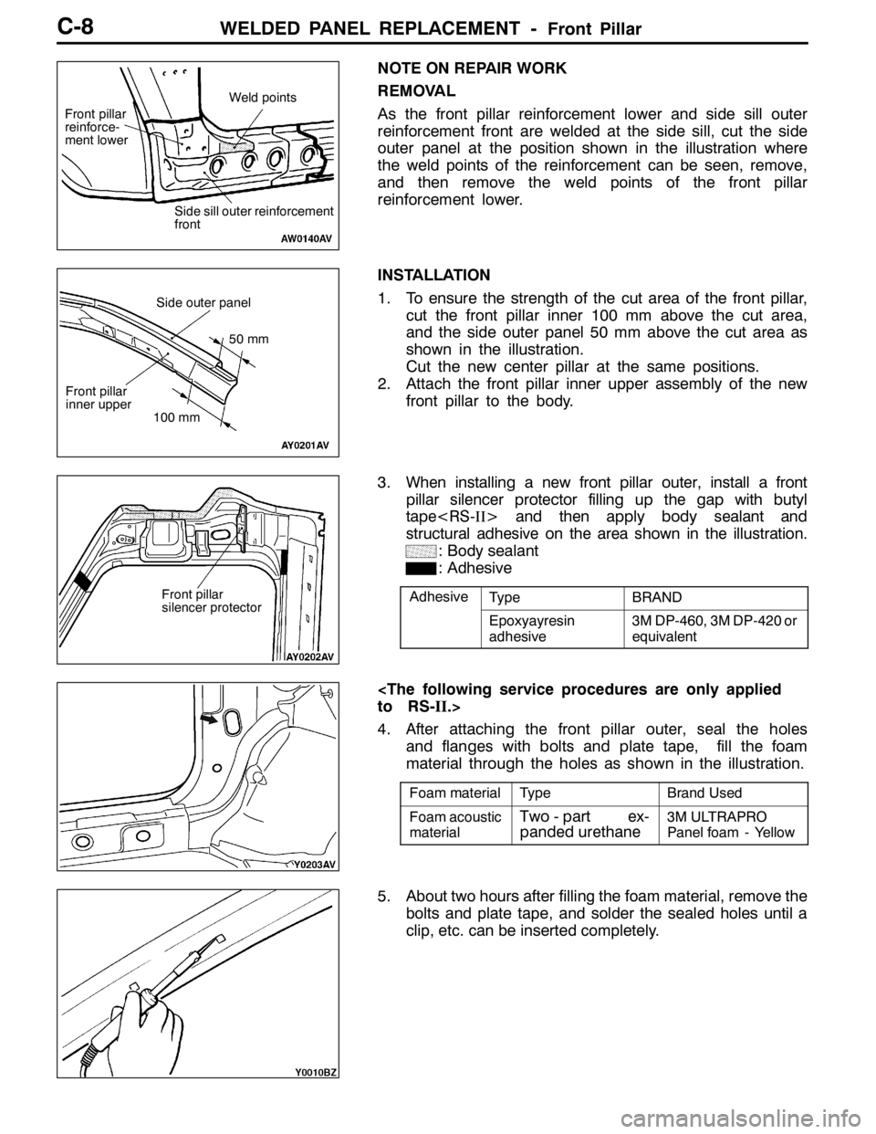
NOTE ON REPAIR WORK
REMOVAL
As the front pillar reinforcement lower and side sill outer
reinforcement front are welded at the side sill, cut the side
outer panel at the position shown in the illustration where
the weld points of the reinforcement can be seen, remove,
and then remove the weld points of the front pillar
reinforcement lower.
INSTALLATION
1. To ensure the strength of the cut area of the front pillar,
cut the front pillar inner 100 mm above the cut area,
and the side outer panel 50 mm above the cut area as
shown in the illustration.
Cut the new center pillar at the same positions.
2. Attach the front pillar inner upper assembly of the new
front pillar to the body.
3.When installing a new front pillar outer, install a front
pillar silencer protector filling up the gap with butyl
tapeandthenapplybodysealantand
structural adhesive on the area shown in the illustration.
: Body sealant
: Adhesive
AdhesiveTypeBRAND
Epoxyayresin
adhesive3M DP-460, 3M DP-420 or
equivalent
to RS-II.>
4.After attaching the front pillar outer, seal the holes
and flanges with bolts and plate tape, fill the foam
material through the holes as shown in the illustration.
Foam materialTypeBrand Used
Foam acoustic
materialTwo - part ex-
panded urethane3M ULTRAPRO
Panel foam - Yellow
5. About two hours after filling the foam material, remove the
bolts and plate tape, and solder the sealed holes until a
clip, etc. can be inserted completely.
Weld points
Side sill outer reinforcement
front Front pillar
reinforce-
ment lower
50 mm
100 mm
Side outer panel
Front pillar
inner upper
Front pillar
silencer protector
Page 53 of 1449
WELDED PANEL REPLACEMENT -Center PillarC-9
CENTER PILLAR
SymbolOperation description
Spot welding
MIG plug welding (J: indicates two panels to be
welded
Y: indicates three panels to be welded)
MIG spot welding
MIG arc welding (continuous)
Braze welding
Anti-corrosion agent application locations
(Use access holes to apply liberally to butt-welded
joints.)
125±10mm
290±10mm125±10mm
A
B
CD
D
B
A
C
Foam acoustic material
REPAIR WELDS
Caution
Do not use heat at areas using foam material as the foam material may burn.
Page 54 of 1449

WELDED PANEL REPLACEMENT -Center PillarC-10
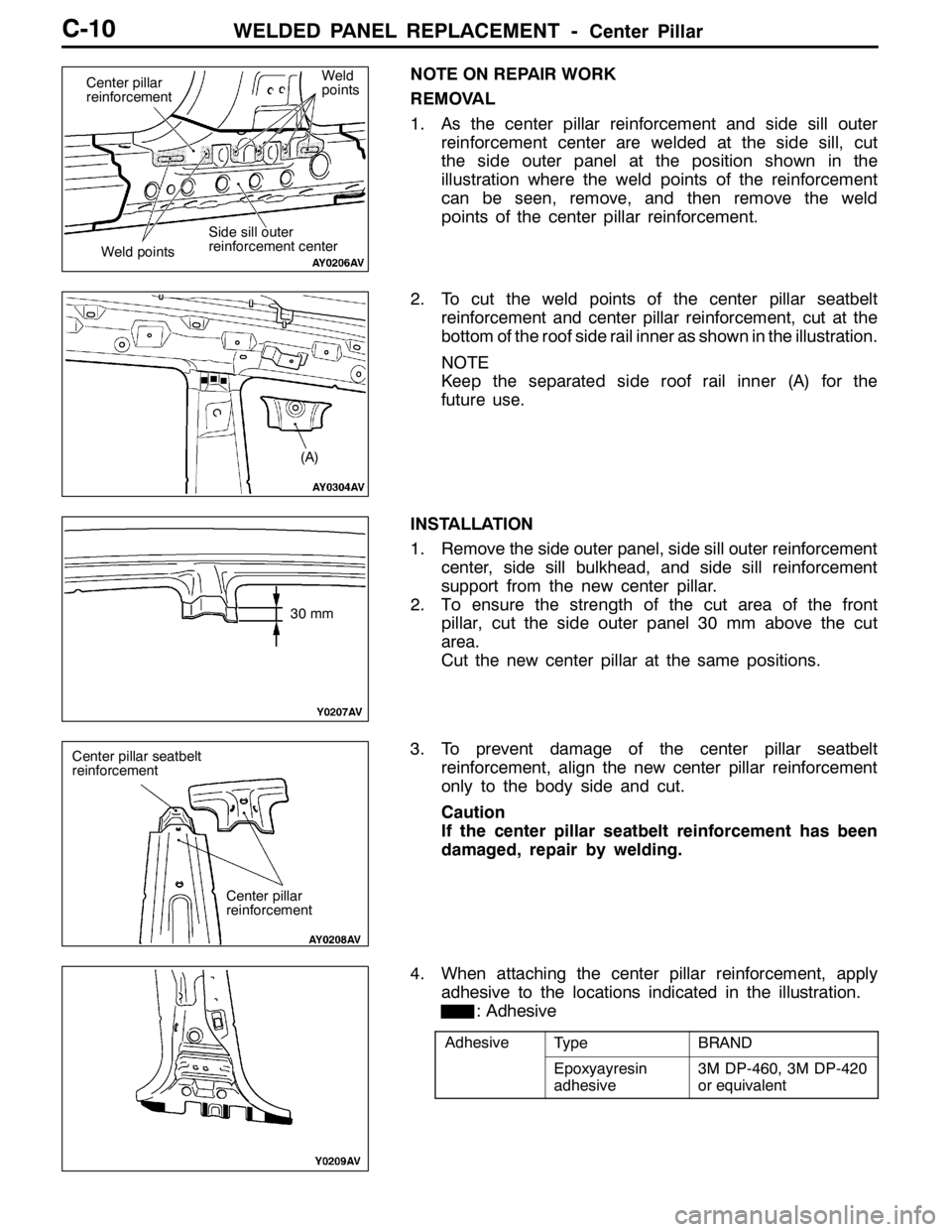
NOTE ON REPAIR WORK
REMOVAL
1.As the center pillar reinforcement and side sill outer
reinforcement center are welded at the side sill, cut
the side outer panel at the position shown in the
illustration where the weld points of the reinforcement
can be seen, remove, and then remove the weld
points of the center pillar reinforcement.
2. To cut the weld points of the center pillar seatbelt
reinforcement and center pillar reinforcement, cut at the
bottom of the roof side rail inner as shown in the illustration.
NOTE
Keep the separated side roof rail inner (A) for the
future use.
INSTALLATION
1. Remove the side outer panel, side sill outer reinforcement
center, side sill bulkhead, and side sill reinforcement
support from the new center pillar.
2.To ensure the strength of the cut area of the front
pillar, cut the side outer panel 30 mm above the cut
area.
Cut the new center pillar at the same positions.
3. To prevent damage of the center pillar seatbelt
reinforcement, align the new center pillar reinforcement
only to the body side and cut.
Caution
If the center pillar seatbelt reinforcement has been
damaged, repair by welding.
4. When attaching the center pillar reinforcement, apply
adhesive to the locations indicated in the illustration.
: Adhesive
AdhesiveTypeBRAND
Epoxyayresin
adhesive3M DP-460, 3M DP-420
or equivalent
Center pillar
reinforcement
Side sill outer
reinforcement center
Weld pointsWeld
points
(A)
30 mm
Center pillar seatbelt
reinforcement
Center pillar
reinforcement