Page 1048 of 1449
BASIC BRAKE SYSTEM -Lubricants/Sealant/Special Tools35A-6
LUBRICANTS
ItemsSpecified LubricantQuantity
Brake fluidDOT3 or DOT4As required
Piston, wheel cylinder body
Piston boot, piston seal, shimRepair kit grease
Guide pin, lock pin, pin boot
Pad assembly
SEALANT
ItemsSpecified sealantRemarks
Fitting3M ATD Part No. 8661, 8663 or equivalentSemi-drying sealant
SPECIAL TOOLS
ToolNumberNameUse
MB991568Push rod adjusting
socketAdjustment of the brake booster push rod
protrusion amount
AMB990964
A: MB990520Brake tool setPushing-in of the disc brake piston
DDisc brake piston pushing-in
MB990998Front hub remover
and installerProvisional holding of the wheel bearing
Page 1055 of 1449

BASIC BRAKE SYSTEM -On-vehicle Service35A-13
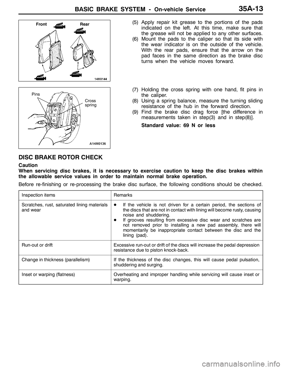
(5) Apply repair kit grease to the portions of the pads
indicated on the left. At this time, make sure that
the grease will not be applied to any other surfaces.
(6) Mount the pads to the caliper so that its side with
the wear indicator is on the outside of the vehicle.
With the rear pads, ensure that the arrow on the
pad faces in the same direction as the brake disc
turns when the vehicle moves forward.
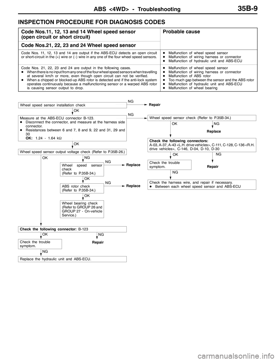
(7) Holding the cross spring with one hand, fit pins in
the caliper.
(8) Using a spring balance, measure the turning sliding
resistance of the hub in the forward direction.
(9) Find the brake disc drag force [the difference in
measurements taken in step(3) and in step(8)].
Standard value: 69 N or less
DISC BRAKE ROTOR CHECK
Caution
When servicing disc brakes, it is necessary to exercise caution to keep the disc brakes within
the allowable service values in order to maintain normal brake operation.
Before re-finishing or re-processing the brake disc surface, the following conditions should be checked.
Inspection itemsRemarks
Scratches, rust, saturated lining materials
and wearDIf the vehicle is not driven for a certain period, the sections of
the discs that are not in contact with lining will become rusty, causing
noise and shuddering.
DIf grooves resulting from excessive disc wear and scratches are
not removed prior to installing a new pad assembly, there will
momentarily be inappropriate contact between the disc and the
lining (pad).
Run-out or driftExcessive run-out or drift of the discs will increase the pedal depression
resistance due to piston knock-back.
Change in thickness (parallelism)If the thickness of the disc changes, this will cause pedal pulsation,
shuddering and surging.
Inset or warping (flatness)Overheating and improper handling while servicing will cause inset or
warping.
Front Rear
Cross
spring
Pins
Page 1065 of 1449
BASIC BRAKE SYSTEM -Disc Brake35A-23
Front
Caution
Take care not to contact the parts or tools to the caliper because the paint of caliper will be scratched.
And if there is brake fluid on the caliper, wipe out quickly.
9
4 1
2 4
56
8
9
Brake caliper kit
Pad set Seal and boot kit
55
2
3 1 10
87
6
3 9
9 7
Clip setShim set
6
106 3
7 5
7
2 1 2
1
4
Grease: Repair kit grease
14±2 N·m
Disassembly steps
1. Pin
2. Cross spring
3. Pad and wear indicator assembly
4. Pad assembly
5. Shim6. Air bleeder screw
AA"7. Piston boot
AA"8. Piston
AB"9. Piston seal
10. Caliper body
Page 1067 of 1449
BASIC BRAKE SYSTEM -Disc Brake35A-25
Rear
Caution
Take care not to contact the parts or tools to the caliper because the paint of caliper will be scratched.
And if there is brake fluid on the caliper, wipe out quickly.
9
4 1 24
5 6
8
9
Brake caliper kit
Pad set Seal and boot kit
5
5 2
3 1 10
876
3 9
9 7
Clip setShim set
6 10 63
7 5
7
21 2 14
Grease: Repair kit grease
14±2 N·m
Disassembly steps
1. Pin
2. Cross spring
3. Pad and wear indicator assembly
4. Pad assembly
5. Shim6. Air bleeder screw
AA"7. Piston boot
AA"8. Piston
AB"9. Piston seal
10. Caliper body
Page 1068 of 1449
BASIC BRAKE SYSTEM -Disc Brake35A-26
LUBRICATION POINTS
Piston seal
Grease: Repair kit grease
Caution
The piston seal inside the
seal and boot kit is coated
with special grease, so do
not wipe this grease off.
Brake fluid: DOT3 or DOT4
Grease: Repair kit greaseGrease: Repair kit grease
Page 1079 of 1449

ABS <4WD> -Troubleshooting35B-9
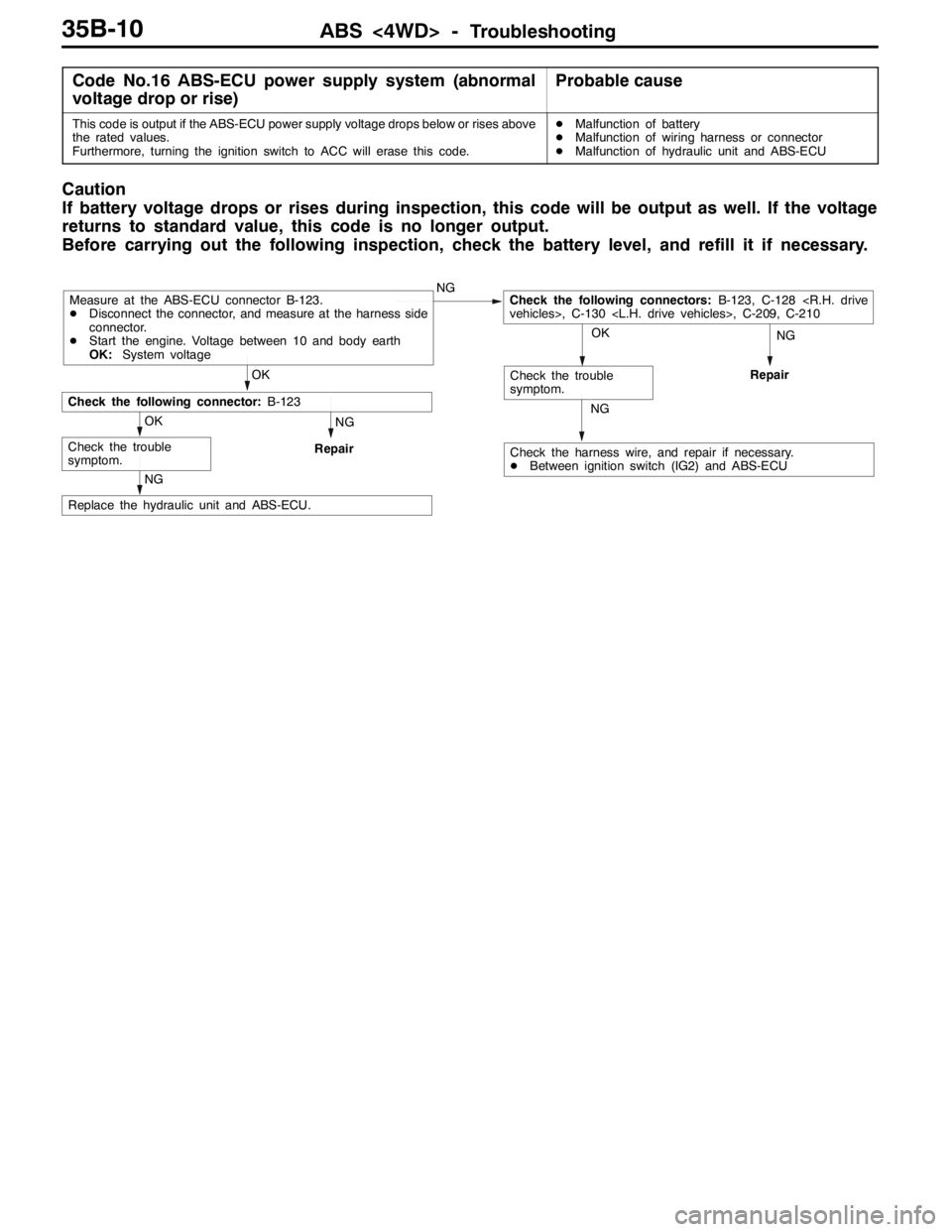
INSPECTION PROCEDURE FOR DIAGNOSIS CODES
Code Nos.11, 12, 13 and 14 Wheel speed sensor
(open circuit or short circuit)Probable cause
Code Nos.21, 22, 23 and 24 Wheel speed sensor
Code Nos. 11, 12, 13 and 14 are output if the ABS-ECU detects an open circuit
or short-circuit in the (+) wire or ( - ) wire in any one of the four wheel speed sensors.DMalfunction of wheel speed sensor
DMalfunction of wiring harness or connector
DMalfunction of hydraulic unit and ABS-ECU
Code Nos. 21, 22, 23 and 24 are output in the following cases.
DWhen there is no input from any one of the four wheel speed sensors when travelling
at several km/h or more, even though open circuit can not be verified.
DWhen a chipped or blocked-up ABS rotor is detected and if the anti-lock system
operates continuously because a malfunctioning sensor or a warped ABS rotor
is causing sensor output to drop.DMalfunction of wheel speed sensor
DMalfunction of wiring harness or connector
DMalfunction of ABS rotor
DToo much gap between the sensor and the ABS rotor
DMalfunction of hydraulic unit and ABS-ECU
DMalfunction of wheel bearing
NG
NG
Replace
OK
Check the harness wire, and repair if necessary.
DBetween each wheel speed sensor and ABS-ECU
NG
Repair
OK
Wheel bearing check
(Refer to GROUP 26 and
GROUP 27 - On-vehicle
Service.)
NG
Repair
NG
Replace the hydraulic unit and ABS-ECU.
OK
Check the trouble
symptom.
Check the following connector:B-123
OK
ABS rotor check
(Refer to P.35B-34.)NG
Replace
NG
Wheel speed sensor
check
(Refer to P.35B-34.)NG
Replace
OK
Wheel speed sensor output voltage check (Refer to P.35B-26.)OK
Check the trouble
symptom.
OK
Check the following connectors:
A-03, A-37, A-43 , C-111, C-128, C-136
drive vehicles>, C-146, D-04, D-10, D-30
OK
Measure at the ABS-ECU connector B-123.
DDisconnect the connector, and measure at the harness side
connector.
DResistances between 6 and 7, 8 and 9, 22 and 31, 29 and
30
OK:1.24 - 1.64 kΩNGWheel speed sensor check (Refer to P.35B-34.)
Wheel speed sensor installation checkNG
Repair
Page 1080 of 1449

ABS <4WD> -Troubleshooting35B-10
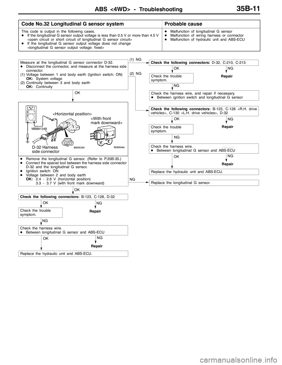
Code No.16 ABS-ECU power supply system (abnormal
voltage drop or rise)Probable cause
This code is output if the ABS-ECU power supply voltage drops below or rises above
the rated values.
Furthermore, turning the ignition switch to ACC will erase this code.DMalfunction of battery
DMalfunction of wiring harness or connector
DMalfunction of hydraulic unit and ABS-ECU
Caution
If battery voltage drops or rises during inspection, this code will be output as well. If the voltage
returns to standard value, this code is no longer output.
Before carrying out the following inspection, check the battery level, and refill it if necessary.
NGNG
Repair
NG
Replace the hydraulic unit and ABS-ECU.
NG
Repair
Check the harness wire, and repair if necessary.
DBetween ignition switch (IG2) and ABS-ECU
OK
Check the trouble
symptom.
OK
Check the trouble
symptom.
OK
Check the following connector:B-123
NGCheck the following connectors:B-123, C-128
vehicles>, C-130 , C-209, C-210Measure at the ABS-ECU connector B-123.
DDisconnect the connector, and measure at the harness side
connector.
DStart the engine. Voltage between 10 and body earth
OK:System voltage
Page 1081 of 1449

ABS <4WD> -Troubleshooting35B-11
Code No.32 Longitudinal G sensor systemProbable cause
This code is output in the following cases.
DIf the longitudinal G sensor output voltage is less than 0.5 V or more than 4.5 V
DIf the longitudinal G sensor output voltage does not change
DMalfunction of longitudinal G sensor
DMalfunction of wiring harness or connector
DMalfunction of hydraulic unit and ABS-ECU
(1) NG
NG
Repair
NG
Check the harness wire, and repair if necessary.
DBetween ignition switch and longitudinal G sensor
OK
Check the trouble
symptom.
Check the following connectors:D-32, C-210, C-213
NG
Repair
NG
OK
Check the trouble
symptom. OK
(2) NG
Measure at the longitudinal G sensor connector D-32.
DDisconnect the connector, and measure at the harness side
connector.
(1) Voltage between 1 and body earth (Ignition switch: ON)
OK:System voltage
(2) Continuity between 3 and body earth
OK:Continuity
Repair
Check the following connectors:B-123, C-128
vehicles>, C-130 , D-32
NGOK
Repair
Check the harness wire.
DBetween longitudinal G sensor and ABS-ECU
Replace the hydraulic unit and ABS-ECU.
MB991348
mark downward>
D-32 Harness
side connector
NG
OK
NG
Repair
NG
OK
Check the trouble
symptom.
Check the following connectors:B-123, C-128, D-32
DRemove the longitudinal G sensor. (Refer to P.35B-35.)
DConnect the special tool between the harness side connector
D-32 and the longitudinal G sensor.
DIgnition switch: ON
DVoltage between 2 and body earth
OK:2.4 - 2.6 V (horizontal position)
3.3 - 3.7 V (with front mark downward)
NGOK
Repair
Check the harness wire.
DBetween longitudinal G sensor and ABS-ECU
Replace the hydraulic unit and ABS-ECU.
Replace the longitudinal G sensor.