2007 MITSUBISHI LANCER EVOLUTION to pair
[x] Cancel search: to pairPage 959 of 1449
REAR AXLE -Troubleshooting
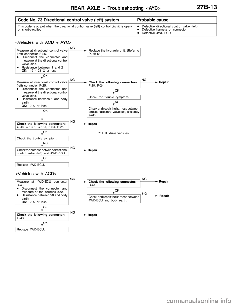
Code No. 73 Directional control valve (left) systemProbable cause
This code is output when the directional control valve (left) control circuit is open-
or short-circuited.DDefective directional control valve (left)
DDefective harness or connector
DDefective 4WD-ECU
NG
Check and repair the harness between
directional control valve (left) and body
earth.
OK
Check the trouble symptom.
OK
Replace 4WD-ECU.
NG
Check the harness between directional
control valve (left) and 4WD-ECU.NG
Repair
OK
Check the trouble symptom.
OK
Check the following connectors:
C-44, C-130*, C-134, F-24, F-25NG
Repair
OK
Measure at directional control valve
(left) connector F-25.
DDisconnect the connector and
measure at the directional control
valve side.
DResistance between 1 and body
earth
OK:2Ωor lessNGCheck the following connectors:
F-25, F-24NG
Repair
Measure at directional control valve
(left) connector F-25.
DDisconnect the connector and
measure at the directional control
valve side.
DResistance between 1 and 2
OK:19 - 21Ωor lessNGReplace the hydraulic unit. (Refer to
P27B-61.)
*: L.H. drive vehicles
OK
Check and repair the harness between
4WD-ECU and body earth.
Measure at 4WD-ECU connector
C-43.
DDisconnect the connector and
measure at the harness side.
DResistance between 50 and body
earth
OK:2Ωor lessNGCheck the following connector:
C-43NG
Repair
OK
Replace 4WD-ECU.
OK
Check the following connector:
C-43NG
RepairNG
Repair
Page 960 of 1449
REAR AXLE -Troubleshooting
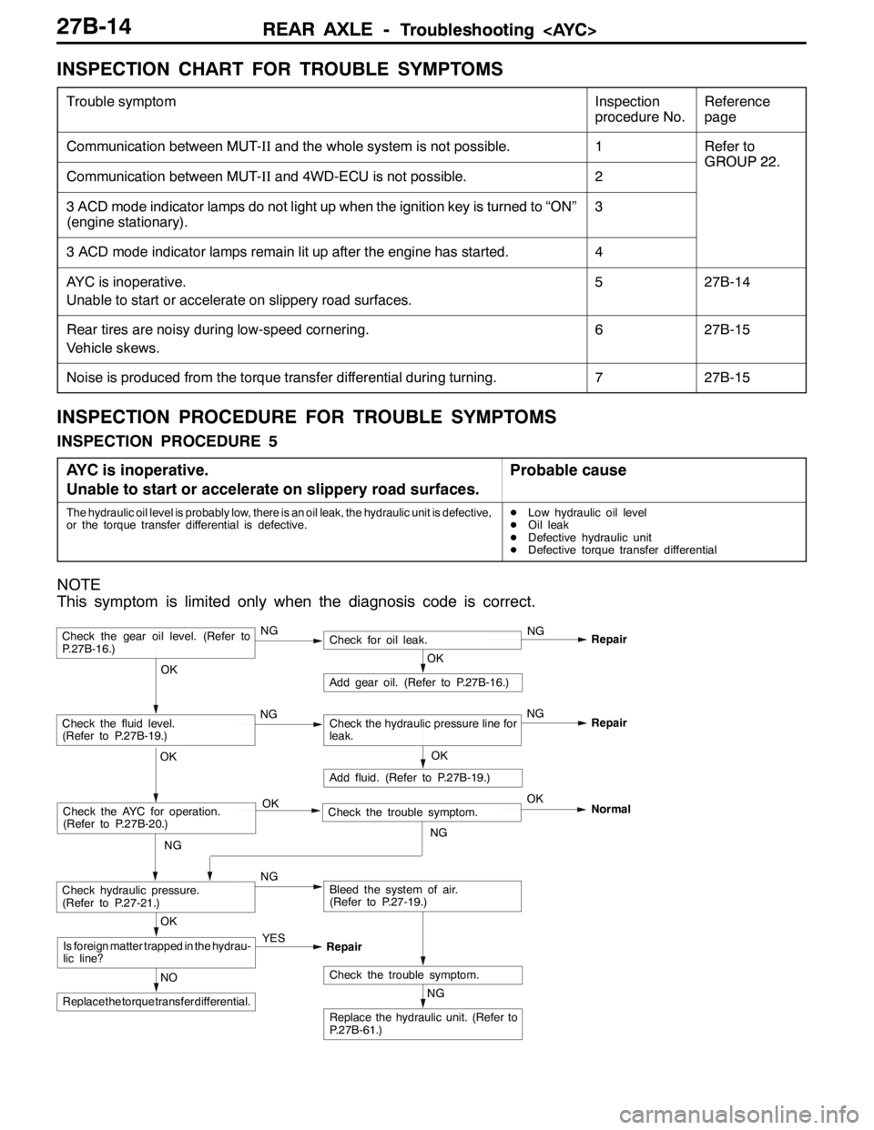
INSPECTION CHART FOR TROUBLE SYMPTOMS
Trouble symptomInspection
procedure No.Reference
page
Communication between MUT-IIand the whole system is not possible.1Refer to
GROUP22
Communication between MUT-IIand 4WD-ECU is not possible.2
GROUP22.
3 ACD mode indicator lamps do not light up when the ignition key is turned to “ON”
(engine stationary).3
3 ACD mode indicator lamps remain lit up after the engine has started.4
AYC is inoperative.
Unable to start or accelerate on slippery road surfaces.527B-14
Rear tires are noisy during low-speed cornering.
Vehicle skews.627B-15
Noise is produced from the torque transfer differential during turning.727B-15
INSPECTION PROCEDURE FOR TROUBLE SYMPTOMS
INSPECTION PROCEDURE 5
AYC is inoperative.
Unable to start or accelerate on slippery road surfaces.
Probable cause
The hydraulic oil level is probably low, there is an oil leak, the hydraulic unit is defective,
or the torque transfer differential is defective.DLow hydraulic oil level
DOil leak
DDefective hydraulic unit
DDefective torque transfer differential
NOTE
This symptom is limited only when the diagnosis code is correct.
NG
Replace the hydraulic unit. (Refer to
P.27B-61.)
NG
Add fluid. (Refer to P.27B-19.)
OKRepair
Check the trouble symptom.NO
Replace the torque transfer differential.
OK
Is foreign matter trapped in the hydrau-
lic line?YES
Repair
OK
Check the fluid level.
(Refer to P.27B-19.)Check the hydraulic pressure line for
leak.
OK
Add gear oil. (Refer to P.27B-16.)
OK
Check hydraulic pressure.
(Refer to P.27-21.)NGBleed the system of air.
(Refer to P.27-19.)
Check the gear oil level. (Refer to
P.27B-16.)NGCheck for oil leak.NG
Repair
Check the AYC for operation.
(Refer to P.27B-20.)Check the trouble symptom. OKOK
NGNormal
NGNG
Page 961 of 1449
REAR AXLE -Troubleshooting
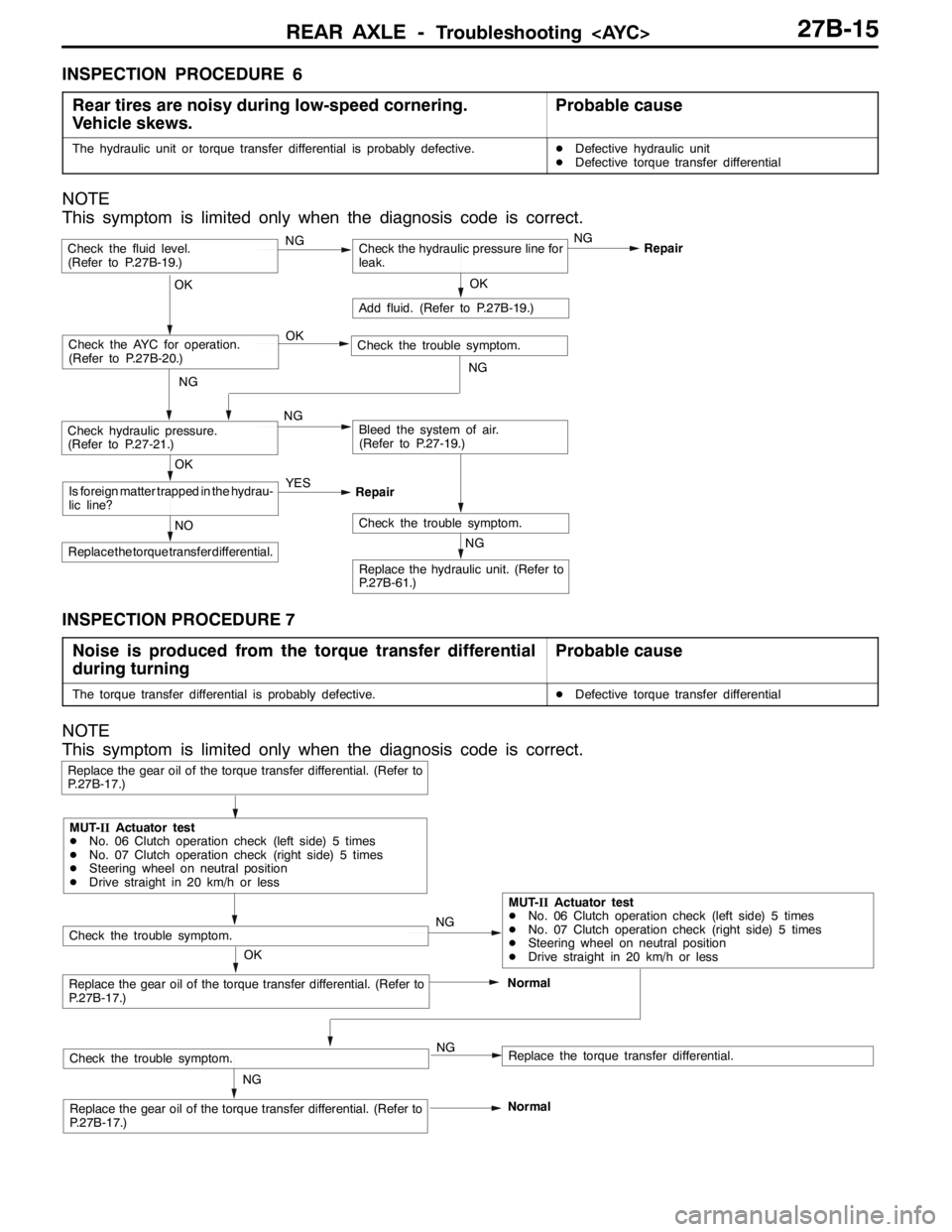
INSPECTION PROCEDURE 6
Rear tires are noisy during low-speed cornering.
Vehicle skews.
Probable cause
The hydraulic unit or torque transfer differential is probably defective.DDefective hydraulic unit
DDefective torque transfer differential
NOTE
This symptom is limited only when the diagnosis code is correct.
NG
Replace the hydraulic unit. (Refer to
P.27B-61.)
NG
Add fluid. (Refer to P.27B-19.)
OKRepair
Check the trouble symptom.NO
Replace the torque transfer differential.
OK
Is foreign matter trapped in the hydrau-
lic line?YES
Repair
Check the fluid level.
(Refer to P.27B-19.)Check the hydraulic pressure line for
leak.
OK
Check hydraulic pressure.
(Refer to P.27-21.)NGBleed the system of air.
(Refer to P.27-19.)
Check the AYC for operation.
(Refer to P.27B-20.)Check the trouble symptom. OK
NG
NGNG
INSPECTION PROCEDURE 7
Noise is produced from the torque transfer differential
during turning
Probable cause
The torque transfer differential is probably defective.DDefective torque transfer differential
NOTE
This symptom is limited only when the diagnosis code is correct.
NG
Replace the gear oil of the torque transfer differential. (Refer to
P.27B-17.)
Replace the gear oil of the torque transfer differential. (Refer to
P.27B-17.)Normal
Replace the gear oil of the torque transfer differential. (Refer to
P.27B-17.)
Replace the torque transfer differential.
Check the trouble symptom.
OKNG
NG
MUT-IIActuator test
DNo. 06 Clutch operation check (left side) 5 times
DNo. 07 Clutch operation check (right side) 5 times
DSteering wheel on neutral position
DDrive straight in 20 km/h or less
MUT-IIActuator test
DNo. 06 Clutch operation check (left side) 5 times
DNo. 07 Clutch operation check (right side) 5 times
DSteering wheel on neutral position
DDrive straight in 20 km/h or less
Check the trouble symptom.
Normal
Page 978 of 1449
REAR AXLE -Drive Shaft27B-32
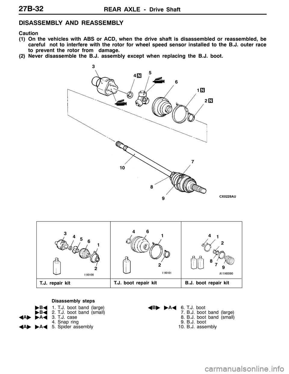
DISASSEMBLY AND REASSEMBLY
Caution
(1) On the vehicles with ABS or ACD, when the drive shaft is disassembled or reassembled, be
careful not to interfere with the rotor for wheel speed sensor installed to the B.J. outer race
to prevent the rotor from damage.
(2) Never disassemble the B.J. assembly except when replacing the B.J. boot.
2
6
4
3
5
7
1
4
2
43
61
2
4
51
2
9
10
1
8
8
97
6
T.J. repair kitT.J. boot repair kit B.J. boot repair kit
Disassembly steps
"BA1. T.J. boot band (large)
"BA2. T.J. boot band (small)
AA""AA3. T.J. case
4. Snap ring
AA""AA5. Spider assemblyAB""AA6. T.J. boot
7. B.J. boot band (large)
8. B.J. boot band (small)
9. B.J. boot
10. B.J. assembly
Page 979 of 1449

REAR AXLE -Drive Shaft27B-33
DISASSEMBLY SERVICE POINTS
AA"T.J. CASE/SPIDER ASSEMBLY REMOVAL
1. Wipe off grease from the spider assembly and the inside
of the T.J. case.
2. Always clean the spider assembly when the grease
contains water or foreign material.
Caution
Do not disassemble the spider assembly.
AB"T.J. BOOT REMOVAL
1. Wipe off grease from the shaft spline.
2. When reusing the T.J. boot, wrap plastic tape around
the shaft spline to avoid damaging the boot.
REASSEMBLY SERVICE POINTS
"AAT.J. BOOT/SPIDER ASSEMBLY/T.J. CASE
INSTALLATION
1. Apply the specified grease furnished in the repair kit to
the spider assembly between the spider axle and the
roller.
Specified grease: Repair kit grease
Caution
(1) The drive shaft joint uses special grease. Do not
mix old and new or different types of grease.
(2) If the spider assembly has been cleaned, take
special care to apply the specified grease.
2. Install the spider assembly to the shaft from the direction
of the spline bevelled section.
3. After applying the specified grease to the T.J. case, insert
the drive shaft and apply grease one more time.
Specified grease: Repair kit grease
Amount to use: 105±10 g
NOTE
The grease in the repair kit should be divided in half
for use, respectively, at the joint and inside the boot.
Caution
The drive shaft joint uses special grease. Do not mix
old and new or different types of grease.Bevelled
section
Page 995 of 1449
REAR AXLE -Differential Carrier
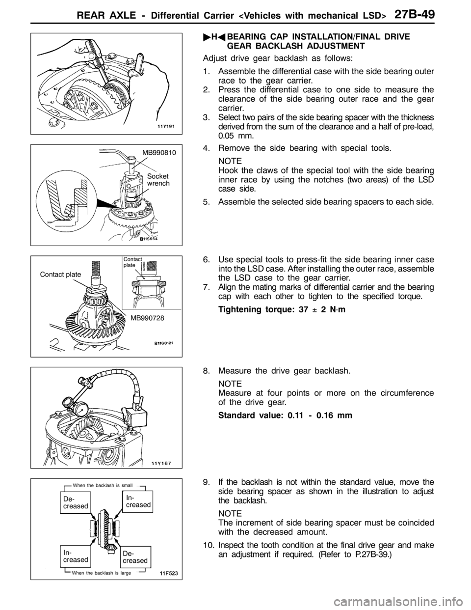
"HABEARING CAP INSTALLATION/FINAL DRIVE
GEAR BACKLASH ADJUSTMENT
Adjust drive gear backlash as follows:
1. Assemble the differential case with the side bearing outer
race to the gear carrier.
2. Press the differential case to one side to measure the
clearance of the side bearing outer race and the gear
carrier.
3. Select two pairs of the side bearing spacer with the thickness
derived from the sum of the clearance and a half of pre-load,
0.05 mm.
4. Remove the side bearing with special tools.
NOTE
Hook the claws of the special tool with the side bearing
inner race by using the notches (two areas) of the LSD
case side.
5. Assemble the selected side bearing spacers to each side.
6. Use special tools to press-fit the side bearing inner case
into the LSD case. After installing the outer race, assemble
the LSD case to the gear carrier.
7. Align the mating marks of differential carrier and the bearing
cap with each other to tighten to the specified torque.
Tightening torque: 37±2N
·m
8. Measure the drive gear backlash.
NOTE
Measure at four points or more on the circumference
of the drive gear.
Standard value: 0.11 - 0.16 mm
9. If the backlash is not within the standard value, move the
side bearing spacer as shown in the illustration to adjust
the backlash.
NOTE
The increment of side bearing spacer must be coincided
with the decreased amount.
10. Inspect the tooth condition at the final drive gear and make
an adjustment if required. (Refer to P.27B-39.)
MB990810
Socket
wrench
Contact plate
MB990728
Contact
plate
De-
creasedIn-
creased
De-
creased In-
creased
When the backlash is large
When the backlash is small
Page 998 of 1449
REAR AXLE -Differential Carrier
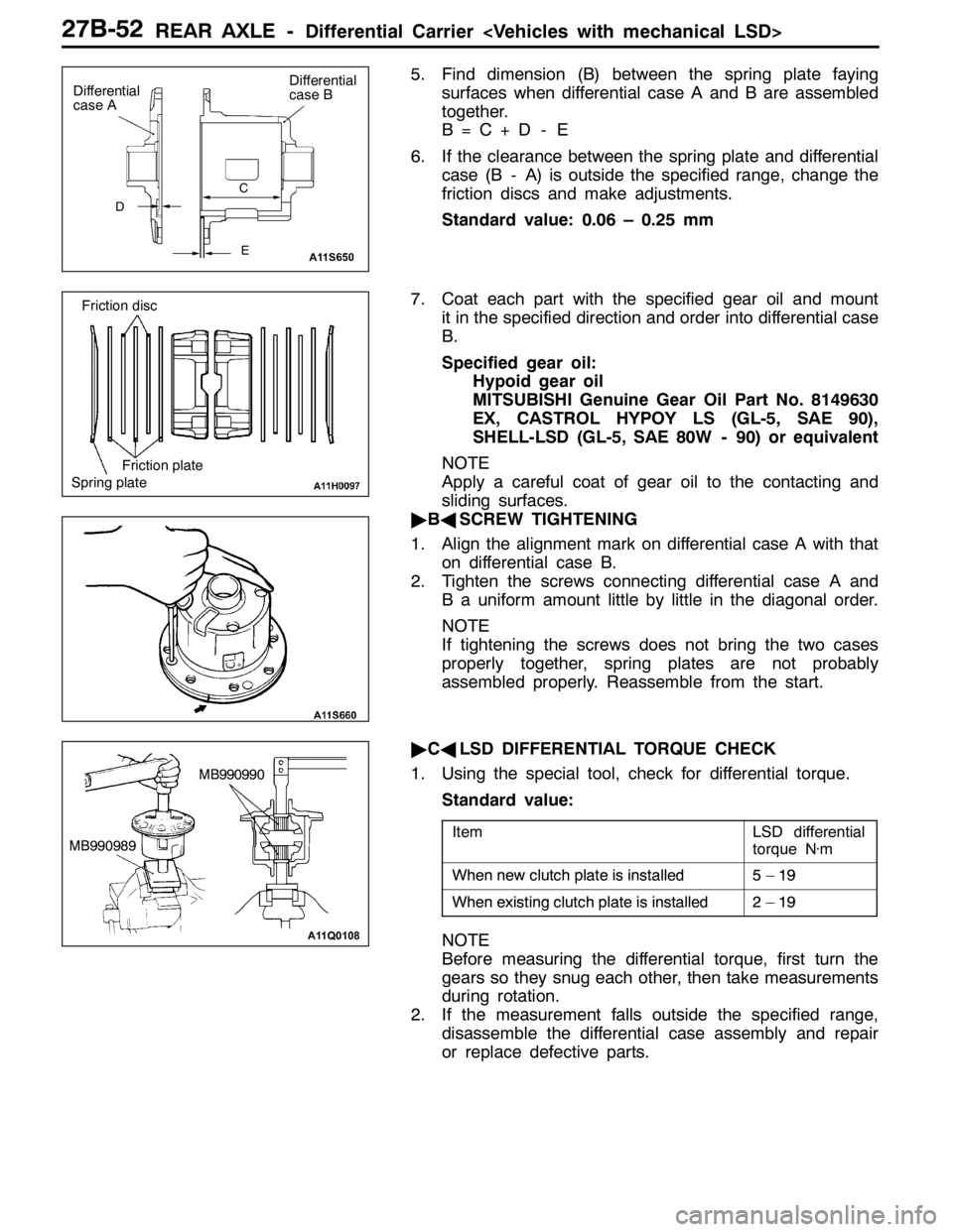
5. Find dimension (B) between the spring plate faying
surfaces when differential case A and B are assembled
together.
B=C+D - E
6. If the clearance between the spring plate and differential
case (B - A) is outside the specified range, change the
friction discs and make adjustments.
Standard value: 0.06 – 0.25 mm
7. Coat each part with the specified gear oil and mount
it in the specified direction and order into differential case
B.
Specified gear oil:
Hypoid gear oil
MITSUBISHI Genuine Gear Oil Part No. 8149630
EX, CASTROL HYPOY LS (GL-5, SAE 90),
SHELL-LSD (GL-5, SAE 80W - 90) or equivalent
NOTE
Apply a careful coat of gear oil to the contacting and
sliding surfaces.
"BASCREW TIGHTENING
1. Align the alignment mark on differential case A with that
on differential case B.
2. Tighten the screws connecting differential case A and
B a uniform amount little by little in the diagonal order.
NOTE
If tightening the screws does not bring the two cases
properly together, spring plates are not probably
assembled properly. Reassemble from the start.
"CALSD DIFFERENTIAL TORQUE CHECK
1. Using the special tool, check for differential torque.
Standard value:
ItemLSD differential
torque N·m
Whennewclutchplateisinstalled5–19When new clutchplateisinstalled5–19
Whenexistingclutchplateisinstalled2–19When existing clutchplateisinstalled2–19
NOTE
Before measuring the differential torque, first turn the
gears so they snug each other, then take measurements
during rotation.
2. If the measurement falls outside the specified range,
disassemble the differential case assembly and repair
or replace defective parts.
D
Differential
case A
E C
Differential
case B
Spring plateFriction plate Friction disc
MB990990
MB990989
Page 1013 of 1449
WHEEL AND TYRE -Troubleshooting31-5
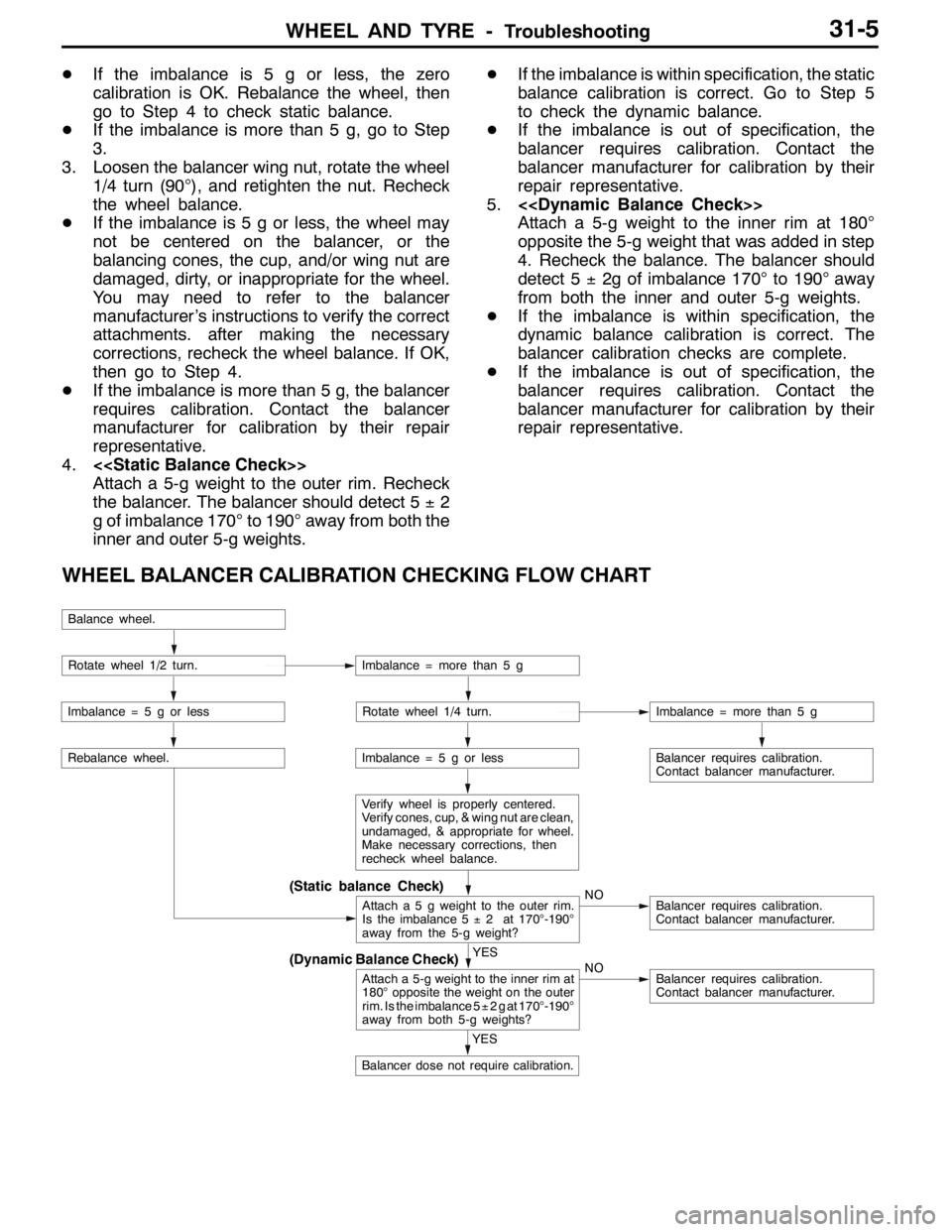
DIf the imbalance is 5 g or less, the zero
calibration is OK. Rebalance the wheel, then
go to Step 4 to check static balance.
DIf the imbalance is more than 5 g, go to Step
3.
3. Loosen the balancer wing nut, rotate the wheel
1/4 turn (90°), and retighten the nut. Recheck
the wheel balance.
DIf the imbalance is 5 g or less, the wheel may
not be centered on the balancer, or the
balancing cones, the cup, and/or wing nut are
damaged, dirty, or inappropriate for the wheel.
You may need to refer to the balancer
manufacturer’s instructions to verify the correct
attachments. after making the necessary
corrections, recheck the wheel balance. If OK,
then go to Step 4.
DIf the imbalance is more than 5 g, the balancer
requires calibration. Contact the balancer
manufacturer for calibration by their repair
representative.
4.<
Attach a 5-g weight to the outer rim. Recheck
the balancer. The balancer should detect 5±2
g of imbalance 170°to 190°away from both the
inner and outer 5-g weights.DIf the imbalance is within specification, the static
balance calibration is correct. Go to Step 5
to check the dynamic balance.
DIf the imbalance is out of specification, the
balancer requires calibration. Contact the
balancer manufacturer for calibration by their
repair representative.
5.<
Attach a 5-g weight to the inner rim at 180°
opposite the 5-g weight that was added in step
4. Recheck the balance. The balancer should
detect 5±2g of imbalance 170°to 190°away
from both the inner and outer 5-g weights.
DIf the imbalance is within specification, the
dynamic balance calibration is correct. The
balancer calibration checks are complete.
DIf the imbalance is out of specification, the
balancer requires calibration. Contact the
balancer manufacturer for calibration by their
repair representative.
WHEEL BALANCER CALIBRATION CHECKING FLOW CHART
(Dynamic Balance Check)
(Static balance Check)
Balance wheel.
Rotate wheel 1/2 turn.Imbalance = more than 5 g
Imbalance = 5 g or lessRotate wheel 1/4 turn.Imbalance = more than 5 g
Imbalance = 5 g or less
Verify wheel is properly centered.
Verify cones, cup, & wing nut are clean,
undamaged, & appropriate for wheel.
Make necessary corrections, then
recheck wheel balance.
Attach a 5 g weight to the outer rim.
Is the imbalance 5±2 at 170°-190°
away from the 5-g weight?NOBalancer requires calibration.
Contact balancer manufacturer.
Balancer requires calibration.
Contact balancer manufacturer.
YES
Attach a 5-g weight to the inner rim at
180°opposite the weight on the outer
rim. Is the imbalance 5±2gat170°-190°
away from both 5-g weights?NOBalancer requires calibration.
Contact balancer manufacturer.
Rebalance wheel.
YES
Balancer dose not require calibration.