2007 MITSUBISHI LANCER EVOLUTION engine
[x] Cancel search: enginePage 528 of 1449

ENGINE LUBRICATION -On-vehicle Service12-4
ON-VEHICLE SERVICE
ENGINE OIL CHECK
1. Pull out the level gauge slowly and check that the oil
level is in the illustrated range.
2. Check that the oil is not excessively dirty, that there is
no coolant or petrol mixed in, and that it has sufficient
viscosity.
ENGINE OIL REPLACEMENT
1. Start the engine and allow it to warm up until the
temperature of the coolant reaches 80_Cto90_C.
2. Remove the engine oil filler cap.
3. Remove the drain plug to drain oil.
Caution
Use care as oil could be hot.
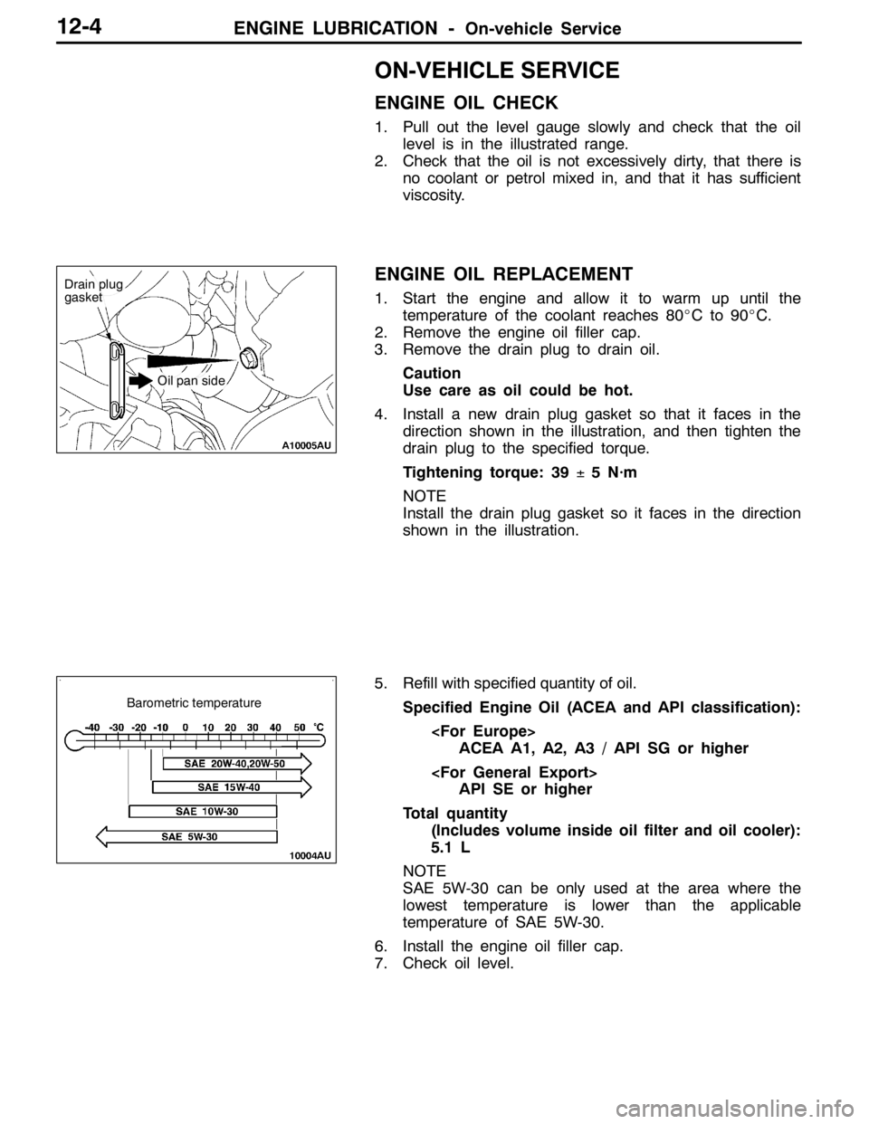
4. Install a new drain plug gasket so that it faces in the
direction shown in the illustration, and then tighten the
drain plug to the specified torque.
Tightening torque: 39±5 N·m
NOTE
Install the drain plug gasket so it faces in the direction
shown in the illustration.
5. Refill with specified quantity of oil.
Specified Engine Oil (ACEA and API classification):
ACEA A1, A2, A3 / API SG or higher
API SE or higher
Total quantity
(Includes volume inside oil filter and oil cooler):
5.1 L
NOTE
SAE 5W-30 can be only used at the area where the
lowest temperature is lower than the applicable
temperature of SAE 5W-30.
6. Install the engine oil filler cap.
7. Check oil level.
Drain plug
gasket
Oil pan side
Barometric temperature
Page 529 of 1449

ENGINE LUBRICATION -On-vehicle Service12-5
OIL FILTER REPLACEMENT
1. Start the engine and allow it to warm up until the
temperature of the coolant reaches 80_Cto90_C.
2. Remove the engine oil filler cap.
3. Remove the drain plug to drain oil.
Caution
Use care as oil could be hot.
4. Remove the under cover.
5. Use the respective tool in the following table to remove
the engine oil filter.
6. Clean the filter bracket side mounting surface.
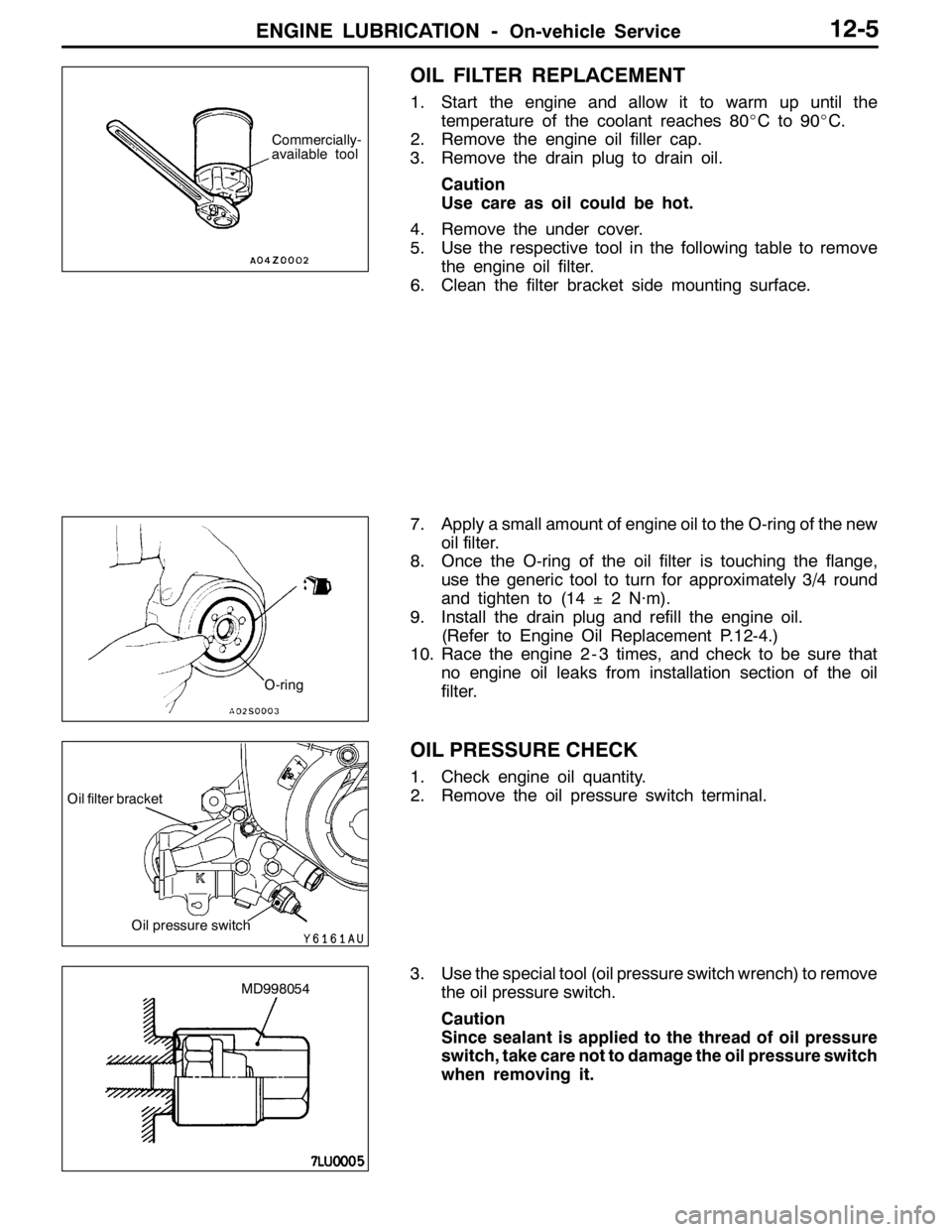
7. Apply a small amount of engine oil to the O-ring of the new
oil filter.
8. Once the O-ring of the oil filter is touching the flange,
use the generic tool to turn for approximately 3/4 round
and tighten to (14±2 N·m).
9. Install the drain plug and refill the engine oil.
(Refer to Engine Oil Replacement P.12-4.)
10. Race the engine 2 - 3 times, and check to be sure that
no engine oil leaks from installation section of the oil
filter.
OIL PRESSURE CHECK
1. Check engine oil quantity.
2. Remove the oil pressure switch terminal.
3. Use the special tool (oil pressure switch wrench) to remove
the oil pressure switch.
Caution
Since sealant is applied to the thread of oil pressure
switch, take care not to damage the oil pressure switch
when removing it.
Commercially-
available tool
O-ring
Oil pressure switch
Oil filter bracket
MD998054
Page 530 of 1449

ENGINE LUBRICATION -On-vehicle Service12-6
4. Install the oil pressure gauge.
NOTE
Use a adapter of PT 1/8 thread.
5. Run the engine to warm it.
6. After the engine has been warmed up, check that oil
pressure is within the standard value.
Standard value:
At idle: 29 kPa or more
At 3,500 r/min: 294 - 686 kPa
7. Remove the oil pressure gauge.
8. Apply the specified sealant to the thread of oil pressure
switch.
Specified sealant: 3M ATD Part No. 8660 or equivalent
9. Use the special tool to tighten the oil pressure switch
to the specified torque.
Tightening torque: 10±2 N·m
Caution
Do not start the engine within one hour after the oil
pressure switch has been installed.
10. Install the oil pressure switch terminal.
MD998054
Page 531 of 1449

ENGINE LUBLICATION -Engine Oli Cooler12-7
ENGINE OIL COOLER
REMOVAL AND INSTALLATION
Caution
If the vehicle is equipped with the Brembo disc brake, during maintenance, take care not to contact
the parts or tools to the caliper because the paint of caliper will be scratched.
Pre-removal and Post-installation Operation
DEngine Oil Draining and Supplying (Refer to P.12-4.)
DUnder Cover Removal and Installation (Refer to GROUP 51 - Front Bumper.)
DSide Cover Removal and Installation
3
4
5 67
12±2 N·m
42±2 N·m
1 2
1 3
42±2 N·m 12±2 N·m
12±2 N·m
8
Removal steps
1. Engine oil cooler tube gasket
2. Engine oil cooler, braket and hose
assembly
3. Engine oil cooler braket
4. Engine oil cooler tube gasket5. Engine oil cooler feed hose
6. Engine oil cooler tube gasket
7. Engine oil cooler return hose
8. Engine oil cooler
Page 534 of 1449

13A-2
MULTIPOINT FUEL
INJECTION (MPI)
CONTENTS
GENERAL INFORMATION 3...................
SERVICE SPECIFICATIONS 6.................
SEALANT 6..................................
SPECIAL TOOLS 7...........................
TROUBLESHOOTING 9.......................
ON-VEHICLE SERVICE 125..................
Fuel Pump Connector Disconnection
(How to Reduce the Fuel Pressure) 125...........
Fuel Pump Operation Check 125.................
Throttle Body (Throttle Valve Area)
Cleaning 126..................................
Throttle Position Sensor Adjustment 126...........
Basic Idle Speed Adjustment 127.................
Fuel Pressure Test 128..........................
Component Location 131........................
Engine Control Relay Continuity Check 132........
Fuel Pump Relay 1, 2 Continuity Check 132........Fuel Pump Relay 3 Continuity Check 132..........
Fuel Pump Resistor Check 132...................
Intake Air Temperature Sensor Check 132.........
Engine Coolant Temperature Sensor Check 133....
Throttle Position Sensor Check 134...............
Oxygen Sensor Check 134......................
Injector Check 136..............................
Resistor (for Injector) Check 138..................
Idle Speed Control Servo (Stepper Motor)
Check 138.....................................
Fuel Pressure Control Solenoid Valve Check 140...
Purge Control Solenoid Valve Check 140..........
EGR Control Solenoid Valve Check 140...........
INJECTOR 141..............................
THROTTLE BODY 143.......................
ENGINE CONTROL RESISTOR, RELAY 146....
ENGINE-ECU 147...........................
Page 535 of 1449

MPI -General Information13A-3
GENERAL INFORMATION
The Multipoint Fuel Injection System consists
of sensors which detect the engine conditions,
the engine-ECU which controls the system
based on signals from these sensors, and
actuators which operate under the control of
the engine-ECU. The engine-ECU carries outactivities such as fuel injection control, idle
speed control and ignition timing control. In
addition, the engine-ECU is equipped with
several diagnosis modes which simplify
troubleshooting when a problem develops.
FUEL INJECTION CONTROL
The injector drive times and injector timing are
controlled so that the optimum air/fuel mixture
is supplied to the engine to correspond to the
continually-changing engine operation condi-
tions.
A single injector is mounted at the intake port
of each cylinder. Fuel is sent under pressure
from the fuel tank by the fuel pump, with the
pressure being regulated by the fuel pressure
regulator. The fuel thus regulated is distributed
to each of the injectors.
Fuel injection is normally carried out once for
each cylinder for every two rotations of the
crankshaft. The firing order is 1-3-4-2. This iscalled sequential fuel injection. The
engine-ECU provides a richer air/fuel mixture
by carrying out “open-loop” control when the
engine is cold or operating under high load
conditions in order to maintain engine
performance. In addition, when the engine is
warm or operating under normal conditions,
the engine-ECU controls the air/fuel mixture
by using the oxygen sensor signal to carry out
“closed-loop” control in order to obtain the
theoretical air/fuel mixture ratio that provides
the maximum cleaning performance from the
three way catalyst.
IDLE AIR CONTROL
The idle speed is kept at the optimum speed
by controlling the amount of air that bypasses
the throttle valve in accordance with changes
in idling conditions and engine load during
idling. The engine-ECU drives the idle speed
control motor to keep the engine running at
the pre-set idle target speed in accordance
with the engine coolant temperature and airconditioner load. In addition, when the air
conditioner switch is turned off and on while
the engine is idling, the idle speed control motor
operates to adjust the throttle valve bypass
air amount in accordance with the engine load
conditions in order to avoid fluctuations in the
engine speed.
IGNITION TIMING CONTROL
The power transistor located in the ignition
primary circuit turns ON and OFF to control
the primary current flow to the ignition coil. This
controls the ignition timing in order to provide
the optimum ignition timing with respect to theengine operating conditions. The ignition timing
is determined by the engine-ECU from the
engine speed, intake air volume, engine coolant
temperature and barometric pressure.
SELF-DIAGNOSIS FUNCTION
DWhen an abnormality is detected in one
of the sensors or actuators related to
emission control, the engine warning lamp
(check engine lamp) illuminates as a
warning to the driver.
DWhen an abnormality is detected in one
of the sensors or actuators, a diagnosis
code corresponding to the abnormality is
output.DThe RAM data inside the engine-ECU that
is related to the sensors and actuators can
be read by means of the MUT-II. In addition,
the actuators can be force-driven under
certain circumstances.
Page 536 of 1449

MPI -General Information13A-4
OTHER CONTROL FUNCTIONS
1. Fuel Pump Control
Turns the fuel pump relay ON so that current
is supplied to the fuel pump while the engine
is cranking or running.
2. A/C Relay Control
Turns the compressor clutch of the A/C
ON and OFF.3. Fan Motor Control
The revolutions of the radiator fan and
condenser fan are controlled in response to
the engine coolant temperature and vehicle
speed.
4. Purge Control Solenoid Valve Control
Refer to GROUP 17.
5. EGR Control Solenoid Valve Control
Refer to GROUP 17.
GENERAL SPECIFICATIONS
ItemsSpecifications
Throttle bodyThrottle bore mm60
Throttle position sensorVariable resistor type
Idle speed control servoStepper motor type
(Stepper motor type by-pass air control system with the
air volume limiter)
Engine-ECUIdentification No.E6T34874
SensorsAir flow sensorKarman vortex type
Barometric pressure sensorSemiconductor type
Intake air temperature sensorThermistor type
Engine coolant temperature sensorThermistor type
Oxygen sensorZirconia type
Vehicle speed sensorMagnetic resistive element type
Camshaft position sensorHall element type
Crank angle sensorHall element type
Detonation sensorPiezoelectric type
Power steering fluid pressure switchContact switch type
ActuatorsEngine control relay typeContact switch type
Fuel pump relay typeContact switch type
Injector type and numberElectromagnetic type, 4
Injector identification markMDL560
EGR control solenoid valveDuty cycle type solenoid valve
Purge control solenoid valveDuty cycle type solenoid valve
Fuel pressure control solenoid valveON/OFF type solenoid valve
Waste gate solenoid valveDuty cycle type solenoid valve
Secondary air control solenoid valveON/OFF type solenoid valve
Fuel pressure
regulatorRegulator pressure kPa294
Page 537 of 1449

MPI -General Information13A-5
MULTI-POINT FUEL INJECTION SYSTEM DIAGRAM
L1 Oxygen sensor (front)
L2 Oxygen sensor (rear)
L3 Air flow sensor
L4 Intake air temperature sensor
L5 Throttle position sensor
L6 Camshaft position sensor
L7 Crank angle sensor
L8 Barometric pressure sensor
L9 Engine coolant temperature sensor
L10 Detonation sensor
Engine-ECU
l1 Injector
l2 Idle speed control servo
l3 Fuel pressure control solenoid valve
l4 Waste gate solenoid valve
l5 EGR control solenoid valve
l6 Purge control solenoid valve
l7 Secondary air control solenoid valve
DPower supply
DIgnition switch IG
DIgnition switch ST
DVehicle speed sensor
DA/C switch
DA/C load signal
DTachometer
DPower steering fluid pressure switch
DAlternator FR terminal
DDiagnosis control terminal
DIntercooler water spray switch (automatic)
DIntercooler water spray switch (manual)DEngine control relay
DFuel pump relay 2, 3
DA/C relay
DIgnition coil
DFan controller
DCondenser fan relay (HI)
DCondenser fan relay (LOW)
DEngine warning lamp
DDiagnosis output
DAlternator G terminal
DIntercooler water spray relay
DIntercooler water spray lamp
L1 Oxygen
sensor
(front)
L4 Intake air
temperature
sensorL5 Throttle
position
sensor
L6 Camshaft
position sensorl1 Injector l2 Idle
speed
control
servo
l6 Purge
control
solenoid
valve
Three-way
catalytic converter Canister
Air
inletVacuum
tank
Fuel
pressure
reguratorFrom
fuel tank
To fuel tank
PCV valveFrom
fuel pump
Waste gate
actuatorL2 Oxygen sensor (rear) Check
valveBy-pass
valve
l5 EGR control
solenoid valve
l4 Waste gate
solenoid valve L8 Barometric
pressure
sensor
L3 Air flow
sensorl7 Secondary
air control
solenoid
valve
Secondary
air valvel3 Fuel pressure
control
solenoid valve
EGR
valve
L9 Engine coolant
temperature sensor
L7 Crank angle sensor
L10 Detonation sensor