Page 1436 of 1449

HEATER, AIR CONDITIONER AND VENTILATION-Evaporator and Air Thermo Sensor55-34
EVAPORATOR AND AIR THERMO SENSOR
REMOVAL AND INSTALLATION
Pre-removal and Post-installation Operations
DRefrigerant Draining and Refilling (Refer to P.55-16, 19.)
1 2
3
4
56
7 8
12±2 N·m
- Pipe coupling
O-ring
A/C compressor oil:
SUN PAG 56
1, 2
9
Disassembly steps
DGlove box (Refer to GROUP 52A –
Instrument Panel.)
DEngine-ECU (Refer to GROUP 14.)
AA"1. Suction pipe connection
AA"2. Liquid pipe B connection
AA"3. Expansion valve4. Expansion valve adapter
5. Joint duct
6. Evaporator cover
AB""AA7. Evaporator
8. Air thermo sensor clip
9. Air thermo sensor
REMOVAL SERVICE POINTS
AA"WHEN DISCONNECTING THE SUCTION PIPE,
LIQUID PIPE B, AND THE EXPANSION VALVE
To prevent the entry of dust or other foreign bodies, plug
the dismantled hose and the nipples of the expansion valves.
Caution
As the compressor oil and receiver are highly moisture
absorbent, use a non-porous material to plug the hose
and nipples.
Page 1438 of 1449
HEATER, AIR CONDITIONER AND VENTILATION-Compressor55-36
COMPRESSOR
REMOVAL AND INSTALLATION
Before Removal
Refrigerant Draining (Refer to P.55-19.)After Removal
DRefrigerant Replenishing (Refer to P.55-16.)
DDrive Belt Tension Check (Refer to GROUP
11A – Engine Adjustment.)
25±4
N·m
2 4
1
- Pipe coupling
O ring
A/C compressor oil:
SUN PAG 56
1, 2
5
3
Removal steps
AA"1. Flexible suction hose connection
AA"2. Flexible discharge hose connection
AB"3. Drive beltAC""AA4. Compressor
5. Compressor bracket
REMOVAL SERVICE POINTS
AA"DISCONNECTION OF FLEXIBLE SUCTION HOSE
AND FLEXIBLE DISCHARGE HOSE
To prevent the entry of dust or other foreign bodies, plug
the dismantled hoses and compressor nipples.
Caution
As the compressor oil and receiver are highly moisture
absorbent, use a non-porous material to plug the hose
and nipples.
Page 1441 of 1449

HEATER, AIR CONDITIONER AND VENTILATION-Compressor55-39
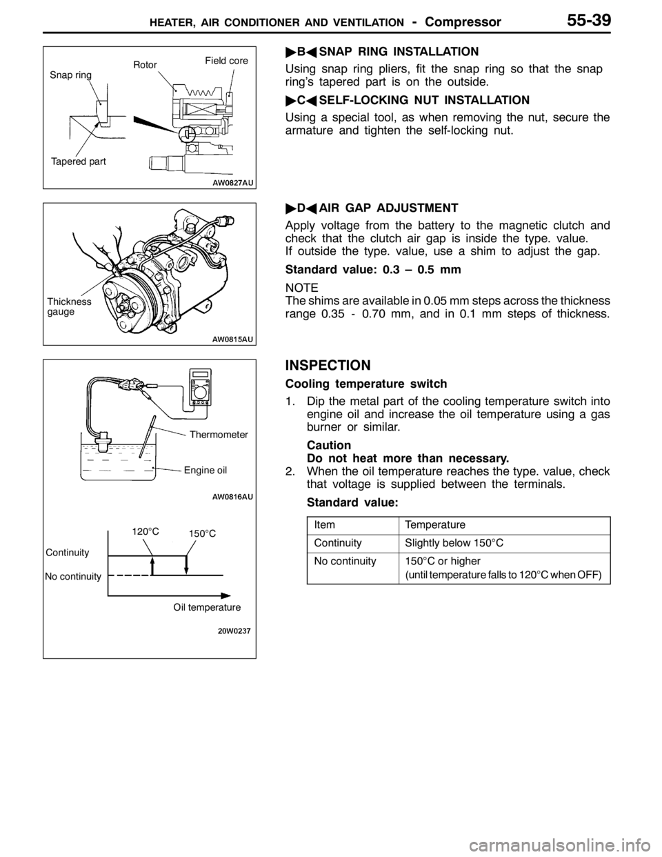
"BASNAP RING INSTALLATION
Using snap ring pliers, fit the snap ring so that the snap
ring’s tapered part is on the outside.
"CASELF-LOCKING NUT INSTALLATION
Using a special tool, as when removing the nut, secure the
armature and tighten the self-locking nut.
"DAAIR GAP ADJUSTMENT
Apply voltage from the battery to the magnetic clutch and
check that the clutch air gap is inside the type. value.
If outside the type. value, use a shim to adjust the gap.
Standard value: 0.3 – 0.5 mm
NOTE
The shims are available in 0.05 mm steps across the thickness
range 0.35 - 0.70 mm, and in 0.1 mm steps of thickness.
INSPECTION
Cooling temperature switch
1. Dip the metal part of the cooling temperature switch into
engine oil and increase the oil temperature using a gas
burner or similar.
Caution
Do not heat more than necessary.
2. When the oil temperature reaches the type. value, check
that voltage is supplied between the terminals.
Standard value:
ItemTemperature
ContinuitySlightly below 150°C
No continuity150°C or higher
(until temperature falls to 120°C when OFF)
Snap ringRotorField core
Tapered part
Thickness
gauge
Thermometer
Engine oil
Continuity
No continuity
Oil temperature
120°C150°C