2007 MITSUBISHI LANCER EVOLUTION engine
[x] Cancel search: enginePage 1123 of 1449

STEERING -On-vehicle Service37A-9
POWER STEERING FLUID LEVEL CHECK
1. Park the vehicle on a flat, level surface, start the engine,
and then turn the steering wheel several times to raise
the temperature of the fluid to approximately 50 - 60_C.
2. With the engine running, turn the wheel all the way to
the left and right several times.
3. Check the fluid in the oil reservoir for foaming or milkiness.
Check the difference of the fluid level when the engine
is stopped, and while it is running. If the change of the
fluid level is 5 mm or more, air bleeding should be done.
POWER STEERING FLUID REPLACEMENT
1. Raise the front wheels on a jack, and then support them
with rigid racks.
2. Disconnect the return hose connection.
3. Connect a vinyl hose to the return hose, and drain the
oil into a container.
4. Disconnect the ignition coil connectors. (Refer to
GROUP16 - Ignition System.)
5. While operating the starting motor intermittently, turn the
steering wheel all the way to the left and right several
times to drain all of the fluid.
6. Connect the return hoses securely, and then secure it
with the clip.
7. Fill the oil reservoir with specified fluid up to the lower
position of the filter, and then bleed air.
Specified fluid:
Automatic transmission fluid DEXRONII
Caution
Do not use ATF-SPIIM and ATF-SPIII.
POWER STEERING SYSTEM BLEEDING
1. Jack up the vehicle and support the front wheels with
rigid racks.
2. Disconnect the ignition coil connectors. (Refer to
GROUP16 - Ignition System.)
3. Cranking the engine with the starter several times
intermittently (during 15 to 20 seconds), turn the steering
wheel left and right fully five or six times.
Caution
(1) During the bleeding, refill the fluid so that the
level never falls below the lower position of the
filter.
(2) Be sure to bleed air only while cranking. If the
bleeding is done with the engine running, the air
will be broken up and absorbed into the fluid.
4. Connect the ignition coil connectors and idle the engine.
5. Turn the steering wheel left and right fully until no bubbles
comes out in the oil reservoir.
6. See that the fluid is not milky and that the fluid level
is up to the specified position on the level gauge.
7. See that the fluid level changes little when the steering
wheel is turned left and right.
8. Check difference in fluid levels between the engine
stopped and running.
Fluid level change: Within 5 mm
While engine
runningWhile engine
stopped
Return hose
Vinyl hose
Page 1124 of 1449

STEERING -On-vehicle Service37A-10
9. If the level changes more than 5 mm, the air is badly
bled. So, bleed air again.
Caution
(1) If the fluid level rises suddenly after the engine
is stopped, the bleeding is incomplete.
(2) Incomplete bleeding causes abnormal noises
from the pump and the flow-control valve. This
could lessen the life of the pump and the other
parts.
OIL PUMP PRESSURE TEST
1. Disconnect the pressure hose from the oil pump, and
then connect the special tools.
2. Bleed the air, and then turn the steering wheel several
times while the vehicle is not moving so that the
temperature of the fluid rises to approximately 50 - 60_C.
3. Start the engine and idle it at 1,000±100 r/min.
4. Fully close the shut-off valve of the pressure gauge and
measure the oil pump relief pressure to confirm that it
is within the standard value range.
Standard value: 8.4 - 9.0 MPa
5. If the standard value is not met, the oil pump is defective.
So, replace the oil pump. Then, measure oil pressure
again.
6. With the pressure gauge shut - off valve fully open, check
the hydraulic pressure in unladen condition.
Standard value: 0.2 - 0.8 MPa
7. If the standard value is not met, the oil line or steering
gear is probably defective. So, repair and measure oil
pressure again.
8. Turn the steering wheel fully either left or right and check
the retention hydraulic pressure.
Standard value: 8.4 - 9.0 MPa
9. If the pressure is below the standard value, disassemble
and reassemble the steering gear. If above, replace the
oil pump. Then, measure oil pressure again.
10. Remove the special tools, and tighten the pressure hose
to the specified torque.
Tightening torque: 18±3 N·m
11. Bleed the system.
Fluid level change: Within 5 mm
While engine
runningWhile engine
stopped
Temperature
gaugePressure
gauge
(MB990662)Shut-off valve
Oil
pumpOil reservoir
Adapter
(MB990994)
Adapter
(MB990993)
Page 1125 of 1449

STEERING -On-vehicle Service37A-11
POWER STEERING OIL PRESSURE SWITCH
CHECK
1. Disconnect the pressure hose from the oil pump, and
then connect the special tools.
2. Bleed the air, and then turn the steering wheel several
times while the vehicle is not moving so that the
temperature of the fluid rises to approximately 50 - 60_C.
3. The engine should be idling.
4. Disconnect the connection of the connector for the oil
pressure switch, and set an ohmmeter in position.
5. Gradually close the shut-off valve of the pressure gauge
and increase the hydraulic pressure, then check whether
or not the hydraulic pressure that activates the switch
is the standard value.
Standard value: 1.8 - 2.4 MPa
6. Gradually open the shut-off valve and reduce the hydraulic
pressure; then check whether or not the hydraulic pressure
that deactivates the switch is the standard value.
Standard value: 1.0 - 2.4 MPa
7. Remove the special tools, and then tighten the pressure
hose to the specified torque.
Tightening torque: 18±3 N·m
8. Bleed the system.
BALL JOINT DUST COVER CHECK
1. Check the dust cover for cracks or damage by pushing
it with finger.
2. If the dust cover is cracked or damaged, replace the
tie rod end.
NOTE
Cracks or damage of the dust cover may cause damage
of the ball joint.
Temperature
gaugeShut-off valve
Oil
pump
ReservoirAdapter
(MB990993)Pressure
gauge
(MB990662)
Adapter
(MB990994)
Page 1144 of 1449

STEERING - Power Steering Oil Pump/Power Steering Oil Hoses37A-30
"BAPRESSURE HOSE ASSEMBLY/SUCTION HOSE
REMOVAL
Install the pressure hose assembly and suction hose as
illustrated.
DISASSEMBLY AND REASSEMBLY
21±3 N·m
3
4
2 1
39±5 N·m
: Automatic transmission fluid DEXRONII
NOTE
Disassembly steps
1. Suction connector
2. O-ring3. Connector
4. Gasket
POWER STEERING OIL HOSES
REMOVAL AND INSTALLATION
Caution
1. Before removing the clock spring, always see GROUP 52B - Caution for Service and Air Bag
Module Clock Spring
2. If the vehicle is equipped with the Brembo disc brake, during maintenance, take care not to
contact the parts or tools to the caliper, because the paint of caliper will be scratched.
3. On the tightening section indicated in the mark (*), lightly tighten the nut first, and then finally
tighten it with the engine weight applied on the body.
Suction hose
Pressure hose
assembly
Marking
Notch
Page 1322 of 1449

54A-2
CHASSIS
ELECTRICAL
CONTENTS
BATTERY 4..............................
SERVICE SPECIFICATION 4....................
ON-VEHICLE SERVICE 4......................
Fluid Level and Specific Gravity Check 4........
Charging 4.................................
Battery Testing Procedure 5...................
IGNITION SWITCH AND IMMOBILIZER
SYSTEM 6...............................
SPECIAL TOOLS 6............................
TROUBLESHOOTING 6........................
IMMOBILIZER-ECU CHECK 10.................
IGNITION SWITCH 11..........................
COMBINATION METER 14................
SERVICE SPECIFICATIONS 14.................
SEALANT 14..................................
SPECIAL TOOLS 15...........................
TROUBLESHOOTING 15.......................
ON-VEHICLE SERVICE 19.....................Speedometer Check 19......................
Tachometer Check 20........................
Fuel Gauge Unit Check 20....................
Engine Coolant Temperature Gauge
Unit Check 21...............................
COMBINATION METER 22.....................
HEADLAMP ASSEMBLY 24...............
SERVICE SPECIFICATIONS 24.................
TROUBLESHOOTING 24.......................
ON-VEHICLE SERVICE 24.....................
Headlamp Aiming 24.........................
Headlamp Intensity Measurement 28...........
Headlamp Bulb(low beam)Replacement28 ....
Headlamp Bulb(high beam)Replacement29 ...
Position Lamp Bulb Replacement29 ...........
Front Turn Signal Lamp Bulb Replacement29 ...
Headlamp Auto Cut Adjustment Procedure29 ...
HeadlampAuto Cut Function Check 29.........
HEADLAMP ASSEMBLY 30....................
CONTINUED ON NEXT PAGE
Page 1327 of 1449

CHASSIS ELECTRICAL -Ignition Switch and Immobilizer System54A-7
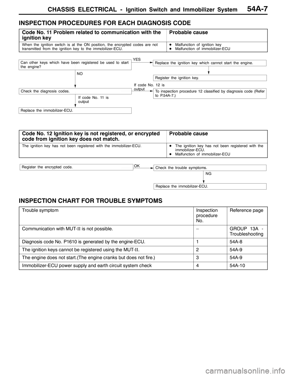
INSPECTION PROCEDURES FOR EACH DIAGNOSIS CODE
Code No. 11 Problem related to communication with the
ignition keyProbable cause
When the ignition switch is at the ON position, the encrypted codes are not
transmitted from the ignition key to the immobilizer-ECU.DMalfunction of ignition key
DMalfunction of immobilizer-ECU
YES
NOCan other keys which have been registered be used to start
the engine?Replace the ignition key which cannot start the engine.
If code No. 12 is
output
Check the diagnosis codes.To inspection procedure 12 classified by diagnosis code (Refer
to P.54A-7.)
Replace the immobilizer-ECU.
Register the ignition key.
If code No. 11 is
output
Code No. 12 Ignition key is not registered, or encrypted
code from ignition key does not match.Probable cause
The ignition key has not been registered with the immobilizer-ECU.DThe ignition key has not been registered with the
immobilizer-ECU.
DMalfunction of immobilizer-ECU
OK
NG
Replace the immobilizer-ECU.
Check the trouble symptoms.Register the encrypted code.
INSPECTION CHART FOR TROUBLE SYMPTOMS
Trouble symptomInspection
procedure
No.Reference page
Communication with MUT-IIis not possible.–GROUP 13A -
Troubleshooting
Diagnosis code No. P1610 is generated by the engine-ECU.154A-8
The ignition keys cannot be registered using the MUT-II.254A-9
The engine does not start.(The engine cranks but does not fire.)354A-9
Immobilizer-ECU power supply and earth circuit system check454A-10
Page 1328 of 1449

CHASSIS ELECTRICAL -Ignition Switch and Immobilizer System54A-8
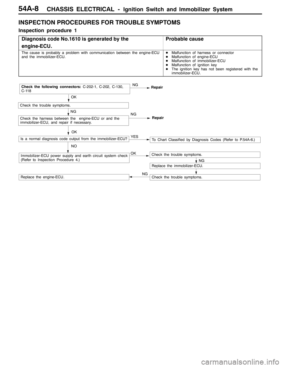
INSPECTION PROCEDURES FOR TROUBLE SYMPTOMS
Inspection procedure 1
Diagnosis code No.1610 is generated by the
engine-ECU.
Probable cause
The cause is probably a problem with communication between the engine-ECU
and the immobilizer-ECU.DMalfunction of harness or connector
DMalfunction of engine-ECU
DMalfunction of immobilizer-ECU
DMalfunction of ignition key
DThe ignition key has not been registered with the
immobilizer-ECU.
OKImmobilizer-ECU power supply and earth circuit system check
(Refer to Inspection Procedure 4.)
OK
Check the trouble symptoms.
NGRepair
NGCheck the following connectors:C-202-1, C-202, C-130,
C-118
Repair
NGCheck the harness between the engine-ECU or and the
immobilizer-ECU, and repair if necessary.
NG
Replace the immobilizer-ECU.
Check the trouble symptoms.
Check the trouble symptoms.Replace the engine-ECU.OK
Is a normal diagnosis code output from the immobilizer-ECU?
NOTo Chart Classified by Diagnosis Codes (Refer to P.54A-6.) YES
NG
Page 1329 of 1449

CHASSIS ELECTRICAL -Ignition Switch and Immobilizer System54A-9
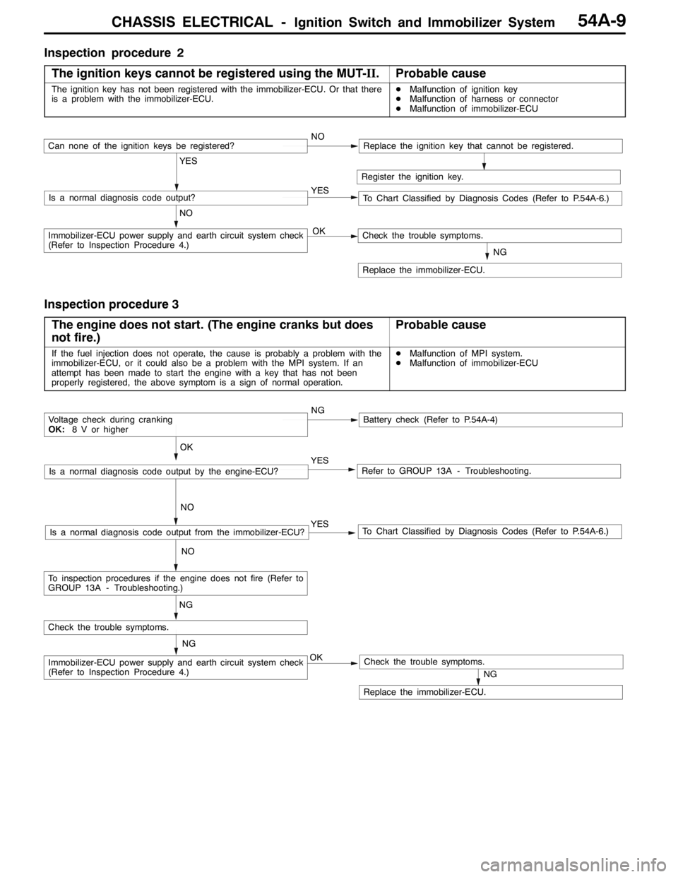
Inspection procedure 2
The ignition keys cannot be registered using the MUT-II.
Probable cause
The ignition key has not been registered with the immobilizer-ECU. Or that there
is a problem with the immobilizer-ECU.DMalfunction of ignition key
DMalfunction of harness or connector
DMalfunction of immobilizer-ECU
Register the ignition key.
YES
NO YESIs a normal diagnosis code output?
NOCan none of the ignition keys be registered?Replace the ignition key that cannot be registered.
To Chart Classified by Diagnosis Codes (Refer to P.54A-6.)
OKImmobilizer-ECU power supply and earth circuit system check
(Refer to Inspection Procedure 4.)
NG
Replace the immobilizer-ECU.
Check the trouble symptoms.
Inspection procedure 3
The engine does not start. (The engine cranks but does
not fire.)
Probable cause
If the fuel injection does not operate, the cause is probably a problem with the
immobilizer-ECU, or it could also be a problem with the MPI system. If an
attempt has been made to start the engine with a key that has not been
properly registered, the above symptom is a sign of normal operation.DMalfunction of MPI system.
DMalfunction of immobilizer-ECU
NGBattery check (Refer to P.54A-4)
YES
NO
Refer to GROUP 13A - Troubleshooting.YES
NO
To Chart Classified by Diagnosis Codes (Refer to P.54A-6.)Is a normal diagnosis code output from the immobilizer-ECU?
OK
Voltage check during cranking
OK:8 V or higher
Is a normal diagnosis code output by the engine-ECU?
NG
OKImmobilizer-ECU power supply and earth circuit system check
(Refer to Inspection Procedure 4.)
NG
Replace the immobilizer-ECU.
Check the trouble symptoms.
Check the trouble symptoms.
NG
To inspection procedures if the engine does not fire (Refer to
GROUP 13A - Troubleshooting.)