Page 1330 of 1449

CHASSIS ELECTRICAL -Ignition Switch and Immobilizer System54A-10
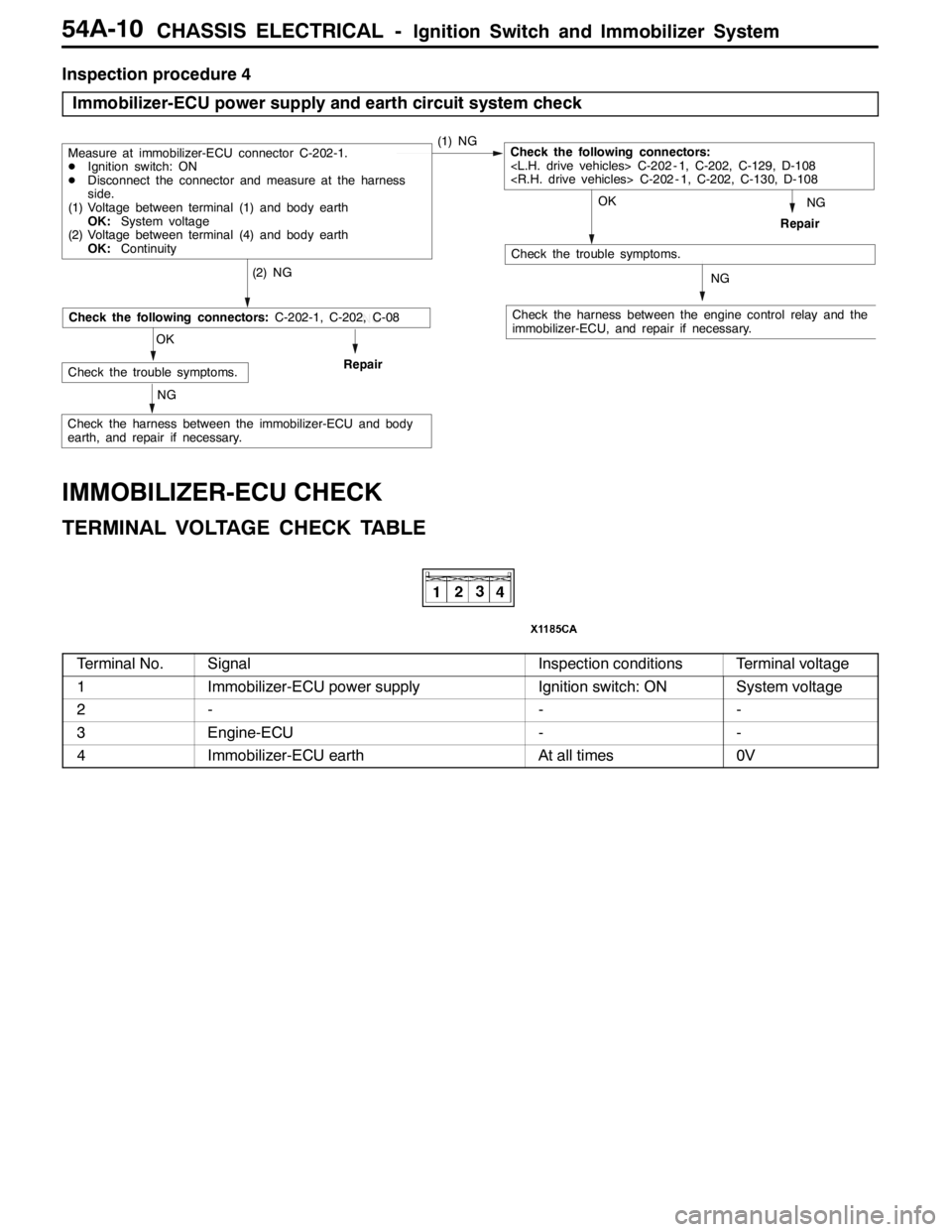
Inspection procedure 4
Immobilizer-ECU power supply and earth circuit system check
NG
Check the harness between the engine control relay and the
immobilizer-ECU, and repair if necessary.
OK
Check the trouble symptoms.
(2) NG
Repair
Measure at immobilizer-ECU connector C-202-1.
DIgnition switch: ON
DDisconnect the connector and measure at the harness
side.
(1) Voltage between terminal (1) and body earth
OK:System voltage
(2) Voltage between terminal (4) and body earth
OK:Continuity(1) NGCheck the following connectors:
C-202 - 1, C-202, C-129, D-108
C-202 - 1, C-202, C-130, D-108
NG
NG
OK
Check the trouble symptoms.Repair
NG
Check the following connectors:C-202-1, C-202, C-08
Check the harness between the immobilizer-ECU and body
earth, and repair if necessary.
IMMOBILIZER-ECU CHECK
TERMINAL VOLTAGE CHECK TABLE
Terminal No.SignalInspection conditionsTerminal voltage
1Immobilizer-ECU power supplyIgnition switch: ONSystem voltage
2---
3Engine-ECU--
4Immobilizer-ECU earthAt all times0V
Page 1332 of 1449

CHASSIS ELECTRICAL -Ignition Switch and Immobilizer System54A-12
INSPECTION
IGNITION SWITCH CONTINUITY CHECK
With ignition switch installed on the vehicle, disconnect ignition
switch connector for inspection.
Ignition key
iti
Terminal No.gy
position12456
LOCK
ACC
ON
START
KEY REMINDER SWITCH CONTINUITY CHECK
With key reminder switch installed on the vehicle, disconnect
key reminder switch connector for inspection.
Ignition key statusTerminal No.gy
46
Remove
Insert
ENCRYPTED CODE REGISTRATION METHOD
AND RESETTING THE CODE TO THE FACTORY
SETTING
Register the encrypted code in the immobilizer-ECU and then
reset the code to the factory setting after parts have been
replaced.
Replacement partEncrypted code
Ignition keyNecessary
Immobilizer-ECUNecessary
Engine-ECU*Necessary
NOTE
*: If the engine-ECU is replaced, the immobilizer-ECU should
be replaced. Each engine-ECU has an individual information
for immobilizer-ECU, and the individual information is
registered in the immobilizer-ECU.
Page 1333 of 1449

CHASSIS ELECTRICAL -Ignition Switch and Immobilizer System54A-13
ENCRYPTED CODE REGISTRATION METHOD
If using an ignition key that has just been newly purchased,
or if the immobilizer-ECU has been replaced, you will need
to register the encrypted codes for each ignition key being
used into the immobilizer-ECU. (A maximum of eight different
encrypted codes can be registered.)
Moreover, when the immobilizer-ECU has been replaced, you
will need to use the MUT-IIto register the password that
the user specifies into the immobilizer-ECU. (Refer to the
MUT-IIinstruction manual for instructions on using the MUT-II.)
Caution
Because registering of the encrypted codes is carried
out after all previously-registered codes have been
erased, you should have ready all of the ignition keys
that have already been registered.
1. Connect the MUT-IIto the diagnosis connector.
Caution
Turn the ignition switch to LOCK (OFF) position before
connecting or disconnecting the MUT-II.
2. Check that diagnosis code No. P1160 is not being
generated by the each engine-ECU. If it is being generated
check according to the Troubleshooting Procedures.
(Refer to GROUP 13A - Troubleshooting.)
3 Use the ignition key that is to be registered to turn on
the ignition switch.
4. Use the MUT-IIto register the encrypted code. If you
are registering two or more codes, use the next key to
the registered to turn on the ignition switch without
disconnecting the MUT-II.
5. Turn off the ignition switch.
6. Check that the engine can be started with each of the
ignition keys.
7. Check the diagnosis output from the each engine-ECU,
and erase code No. P1160 if it appears. (Refer to GROUP
13A - Troubleshooting.)
8. Disconnect the MUT-II. This completes the registration
operation.
dummy
Page 1334 of 1449

CHASSIS ELECTRICAL -Combination Meter54A-14
COMBINATION METER
Caution
Never remove pointer of combination meter. This may cause damage of combination meter.
SERVICE SPECIFICATIONS
ItemStandard valueLimit value
Indication range of speedometer km/hAt 40 km/h37 - 45–gp
At 80 km/h75 - 88–
At 120 km/h113 - 132–
At 160 km/h150 - 176–
Deflection of speedometer pointer (Vehicle speed: 35 km/h or more)–±3
Indication allowance of tachometer rpmEngine Speed: 700 rpm±70–p
Engine Speed: 2,000 rpm- 100 +150–
Engine Speed: 3,000 rpm- 100 +225–
Engine Speed: 4,000 rpm- 125 +275–
Engine Speed: 5,000 rpm- 125 +325–
Engine Speed: 6,000 rpm- 125 +375–
Engine Speed: 7,000 rpm- 100 +400–
Engine Speed: 8,000 rpm+400–
Basic resistance of fuel gauge unit
Mi(SUb)Ω
Position F2±1(2±1)–gg
Main (SUb)ΩPosition E41±1 (69±1)–
Float height of fuel gauge unit
Mi(SUb)
Position F33.3 (10.7)–ggg
Main (SUb) mmPosition E121.9 (138.6)–
Basic resistance of water temperature gauge unitΩ70_C104±13.5–
Internal resistance of combination meterΩTerminal No. 1 - 50233±3–
Terminal No. 1 - 51181±2–
SEALANT
ItemSpecified sealantRemark
Water temperature gauge unit3M ATD Part No.1215 or equivalentSemi-drying sealant
Page 1336 of 1449

CHASSIS ELECTRICAL -Combination Meter54A-16
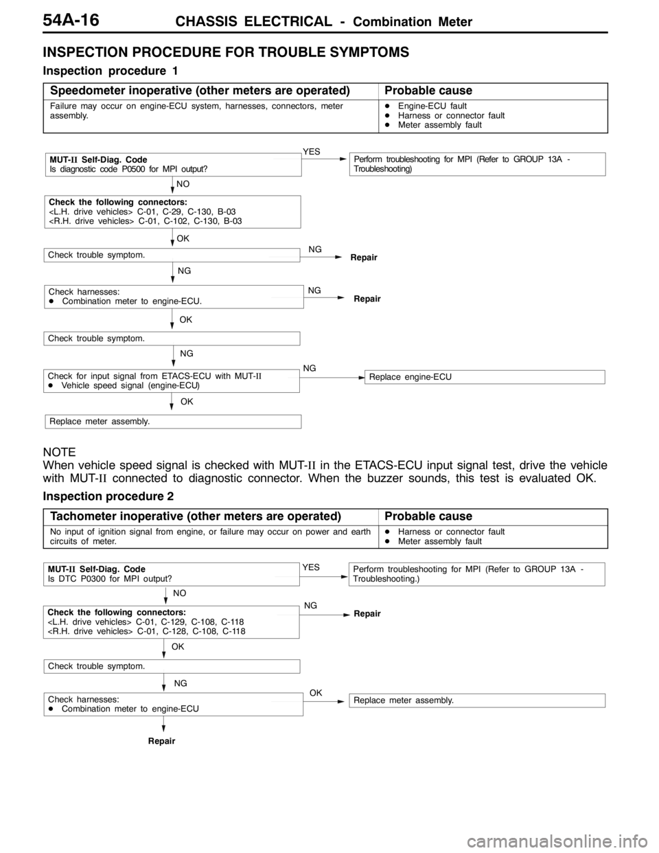
INSPECTION PROCEDURE FOR TROUBLE SYMPTOMS
Inspection procedure 1
Speedometer inoperative (other meters are operated)
Probable cause
Failure may occur on engine-ECU system, harnesses, connectors, meter
assembly.DEngine-ECU fault
DHarness or connector fault
DMeter assembly fault
NO
MUT-IISelf-Diag. Code
Is diagnostic code P0500 for MPI output?YESPerform troubleshooting for MPI (Refer to GROUP 13A -
Troubleshooting)
OK
NG
Check the following connectors:
C-01, C-29, C-130, B-03
C-01, C-102, C-130, B-03
Repair
OK
Check trouble symptom.
NG
NG
RepairCheck harnesses:
DCombination meter to engine-ECU.
Check trouble symptom.
NG
Replace meter assembly.
OK
Check for input signal from ETACS-ECU with MUT-II
DVehicle speed signal (engine-ECU)NGReplace engine-ECU
NOTE
When vehicle speed signal is checked with MUT-IIin the ETACS-ECU input signal test, drive the vehicle
with MUT-IIconnected to diagnostic connector. When the buzzer sounds, this test is evaluated OK.
Inspection procedure 2
Tachometer inoperative (other meters are operated)
Probable cause
No input of ignition signal from engine, or failure may occur on power and earth
circuits of meter.DHarness or connector fault
DMeter assembly fault
OK
NO
MUT-IISelf-Diag. Code
Is DTC P0300 for MPI output?YESPerform troubleshooting for MPI (Refer to GROUP 13A -
Troubleshooting.)
NG
NG
RepairRepair
Check trouble symptom.
OK
Check the following connectors:
C-01, C-129, C-108, C-118
C-01, C-128, C-108, C-118
Replace meter assembly.Check harnesses:
DCombination meter to engine-ECU
Page 1340 of 1449

CHASSIS ELECTRICAL -Combination Meter54A-20
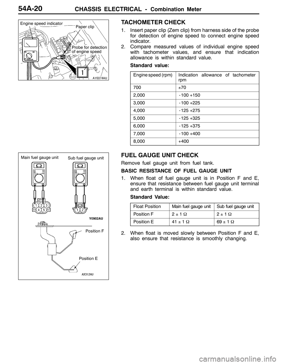
TACHOMETER CHECK
1. Insert paper clip (Zem clip) from harness side of the probe
for detection of engine speed to connect engine speed
indicator.
2. Compare measured values of individual engine speed
with tachometer values, and ensure that indication
allowance is within standard value.
Standard value:
Engine speed (rpm)Indication allowance of tachometer
rpm
700±70
2,000- 100 +150
3,000- 100 +225
4,000- 125 +275
5,000- 125 +325
6,000- 125 +375
7,000- 100 +400
8,000+400
FUEL GAUGE UNIT CHECK
Remove fuel gauge unit from fuel tank.
BASIC RESISTANCE OF FUEL GAUGE UNIT
1. When float of fuel gauge unit is in Position F and E,
ensure that resistance between fuel gauge unit terminal
and earth terminal is within standard value.
Standard Value:
Float PositionMain fuel gauge unitSub fuel gauge unit
Position F2±1Ω2±1Ω
Position E41±1Ω69±1Ω
2. When float is moved slowly between Position F and E,
also ensure that resistance is smoothly changing.
Paper clipEngine speed indicator
Probe for detection
of engine speed
Position F
Position E Main fuel gauge unit
Sub fuel gauge unit
Page 1341 of 1449

CHASSIS ELECTRICAL -Combination Meter54A-21
FLOAT HEIGHT OF FUEL GAUGE UNIT
When float is moved to contact float arm on stopper,
ensure that Position F (A) and E (B) are within standard
value.
Standard Value:
FloatPositionMainfuelgaugeunitSubfuelgaugeunitFloatPositionMainfuelgaugeunitSubfuelgaugeunit
Position F (A)33.3 mm10.7 mm
Position E (B)121.9 mm138.6 mm
ENGINE COOLANT TEMPERATURE GAUGE
UNIT CHECK
1. Drain coolant. (Refer to GROUP 14 - On-vehicle Service)
2. Remove water temperature gauge unit.
3. Put water temperature gauge unit into the hot water in
specified temperature, and ensure that basic resistance
is within standard value.
Standard value: 70_C 104±13.5Ω
Reference value:
TemperatureResistanceΩ
50_C230
60_C155
80_C73
4. After inspection, apply specified sealant at threads of
water temperature gauge unit, and tighten to the specified
torque.
Semi-drying sealant: 3M ATD Part No.1215 or
equivalent
5. Refill coolant. (Refer to GROUP 14 - On-vehicle Service.)
Main fuel gauge unit
Sub fuel gauge unit
A
B
A
B
ThermometerCircuit tester
11±1 N·m
Page 1348 of 1449

CHASSIS ELECTRICAL -Headlamp Assembly54A-28
HEADLAMP INTENSITY MEASUREMENT
1. Using a photometer, and following its manufacture’s
instruction manual.
2. Maintain an engine speed of 2,000 r/min., with the battery
in the charging condition
3. Set the headlamps to high beam
4. Measure the headlamp centre intensity (a point of H line
and V line) and check to be sure that the limit value
is satisfied.
Limit:
High beam 30,000 cd or more per one headlamp
NOTE
1. There may be special local regulations pertaining to
headlamp intensity, be sure to make any adjustments
necessary to satisfy such regulations.
2. If an illuminometer is used to make the measurements,
convert its values to photometer values by using the
following formula.
I=Er
2Where:
I=intensity (cd)
E=illumination (lux)
r=distance (m) from headlamps to illuminometer
Caution
1. On the headlamp not yet adjusted, perform aiming
with connector removed and the lamps switched off,
if applicable. In addition, care should be taken to
prevent a change of optical axis when connector is
reconnected.
2. Plastic outer lens are equipped with headlamps. When
lens surface is covered with materials for not
penetrating light, headlamp operation time should be
within 3 minutes. In addition, masking such as taping
should not be performed.
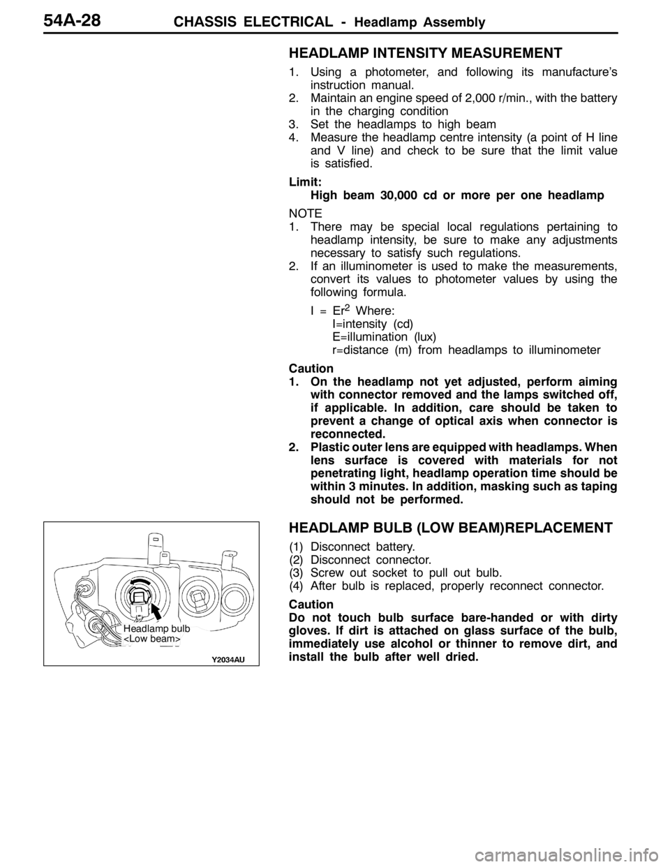
HEADLAMP BULB (LOW BEAM)REPLACEMENT
(1) Disconnect battery.
(2) Disconnect connector.
(3) Screw out socket to pull out bulb.
(4) After bulb is replaced, properly reconnect connector.
Caution
Do not touch bulb surface bare-handed or with dirty
gloves. If dirt is attached on glass surface of the bulb,
immediately use alcohol or thinner to remove dirt, and
install the bulb after well dried.
Headlamp bulb