Page 859 of 1449

MANUAL TRANSMISSION - Transfer Assembly22A-51
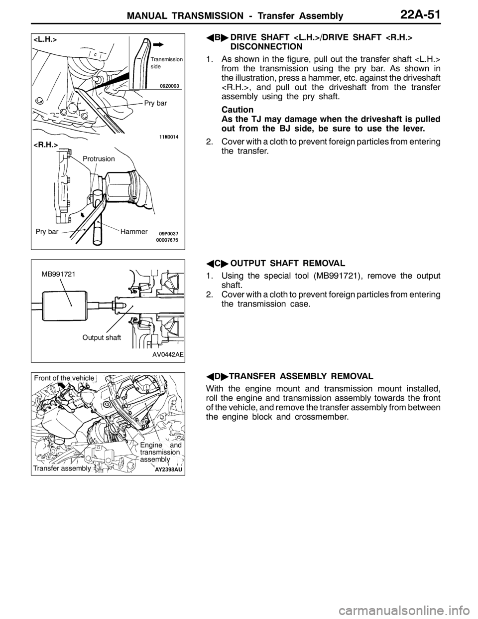
AB"DRIVE SHAFT /DRIVE SHAFT
DISCONNECTION
1. As shown in the figure, pull out the transfer shaft
from the transmission using the pry bar. As shown in
the illustration, press a hammer, etc. against the driveshaft
, and pull out the driveshaft from the transfer
assembly using the pry shaft.
Caution
As the TJ may damage when the driveshaft is pulled
out from the BJ side, be sure to use the lever.
2. Cover with a cloth to prevent foreign particles from entering
the transfer.
AC"OUTPUT SHAFT REMOVAL
1. Using the special tool (MB991721), remove the output
shaft.
2. Cover with a cloth to prevent foreign particles from entering
the transmission case.
AD"TRANSFER ASSEMBLY REMOVAL
With the engine mount and transmission mount installed,
roll the engine and transmission assembly towards the front
of the vehicle, and remove the transfer assembly from between
the engine block and crossmember.
Transmission
side
Pry bar
Pry barHammer
Protrusion
MB991721
Output shaft
Engine and
transmission
assembly
Transfer assembly
Front of the vehicle
Page 860 of 1449
MANUAL TRANSMISSION - Transmission Assembly22A-52
TRANSMISSION ASSEMBLY
REMOVAL AND INSTALLATION
Pre-removal and Post-installation Operation
DTransfer Assembly Removal and Installation (Refer to P.22A-49.)
DStarter Motor Removal and Installation (Refer to GROUP 16.)
DAir Cleaner Bracket Removal and Installation (Refer to GROUP 15 - Air Cleaner.)
DRear Roll Rod Assembly and Rear Roll Rod Bracket , Rear Roll Mount
Removal and Installation (Refer to GROUP 32 - Engine Roll Stopper.)
1
2
3 45
5 6
7
18±3 N·m18±3 N·m
18±3 N·m
70±10 N·m
Removal steps
1. Transmission harness clamp
2. Back-up lamp switch connector
connection
3. Vehicle speed sensor connector
connection
4. Clutch release cylinder and clutch
oil pipe5. Snap pin
6. Shift cable and select cable as-
sembly connection
7. Rear roll mount bracket
AA"DEngine and transmission
assembly supporting
Page 861 of 1449
MANUAL TRANSMISSION - Transmission Assembly22A-53
10
10 11
9
1412 88
13
48±5 N·m
48±5 N·m
48±5 N·m
48±5 N·m
9.0±1.0 N·m
26±5 N·m
82±7 N·m*
47±7 N·m*
8. Transmission assembly upper part
coupling bolts
AA"9. Transmission mount assembly
"AA10. Transmission mount stopper
11. Transmission mount bracket
AB"DEngine assembly supporting
AC"DClutch release bearing connection
12. Bell housing cover13. Transmission assembly lower part
coupling bolts
14. Transmission assembly
Caution
*: Indicates parts which should be initially tightened,
and then fully tightened after placing the vehicle
horizontally and loading the full weight of the engine
on the vehicle body.
REMOVAL SERVICE POINTS
AA"ENGINE AND TRANSMISSION ASSEMBLY
SUPPORTING/TRANSMISSION MOUNT
ASSEMBLY REMOVAL
While supporting the engine and transmission assembly with
a garage jack, remove the transmission mount assembly.Engine and transmission
assembly
Garage jack
Page 862 of 1449

MANUAL TRANSMISSION - Transmission Assembly22A-54
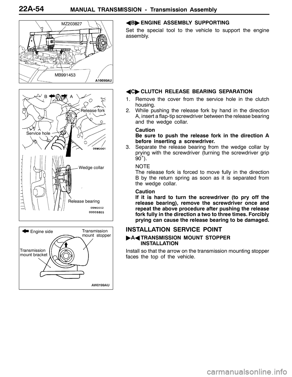
AB"ENGINE ASSEMBLY SUPPORTING
Set the special tool to the vehicle to support the engine
assembly.
AC"CLUTCH RELEASE BEARING SEPARATION
1. Remove the cover from the service hole in the clutch
housing.
2. While pushing the release fork by hand in the direction
A, insert a flap-tip screwdriver between the release bearing
and the wedge collar.
Caution
Be sure to push the release fork in the direction A
before inserting a screwdriver.
3. Separate the release bearing from the wedge collar by
prying with the screwdriver (turning the screwdriver grip
90˚).
NOTE
The release fork is forced to move fully in the direction
B by the return spring as soon as it is separated from
the wedge collar.
Caution
If it is hard to turn the screwdriver (to pry off the
release bearing), remove the screwdriver once and
repeat the above procedure after pushing the release
fork fully in the direction a two to three times. Forcibly
prying can cause the release bearing to be damaged.
INSTALLATION SERVICE POINT
"AATRANSMISSION MOUNT STOPPER
INSTALLATION
Install so that the arrow on the transmission mounting stopper
faces the top of the vehicle.
MZ203827
MB991453
BA
Service hole
Release fork
Wedge collar
Release bearing
Transmission
mount bracket
Transmission
mount stopper Engine side
Page 872 of 1449

MANUAL TRANSMISSION OVERHAUL -Specifications/Service Specifications22B-6
SPECIFICATIONS
TRANSMISSION MODEL TABLE
Transmission
modelGear ratioSpeedometer
gear ratioFinal
reduction
ratioFront LSDVehicle modelEngine model
W5M51 - 2 - X5BA28/364.529CT9A4G63 - I/C•T/C
W5M51 - 2 - X5B1B28/364.529Not providedCT9A4G63 - I/C •T/C
W5M51 - 2 - X5B2C28/364.529ProvidedCT9A4G63 - I/C •T/C
W5M51 - 2 - X5B3B28/364.529Not providedCT9A4G63 - I/C •T/C
W5M51 - 2 - X5B4C28/364.529ProvidedCT9A4G63 - I/C •T/C
GEAR RATIO TABLE
ABC
1st2.9282.785←
2nd1.950←←
3rd1.407←1.444
4th1.031←1.096
5th0.720←0.825
Reverse3.416←←
Transfer gear ratio0.3018←←
SERVICE SPECIFICATIONS
ItemsStandard value mmLimit value mm
Input shaft end play0.05 loose to 0.17 loose-
Input shaft front bearing end play0.01 tight to 0.12 loose-
Input shaft rear bearing end play0.01 tight to 0.12 loose-
Input shaft 5th speed gear end play0.01 tight to 0.09 loose-
Output shaft preload0.13 tight to 0.18 tight-
Output shaft bearing end play0.01 tight to 0.09 loose-
Output shaft 3rd speed gear end play0.01 tight to 0.09 loose-
Center differential case preload0.05 tight to 0.11 tight-
Center differential case pinion backlash0.025 - 0.150-
Clearance between synchronizer ring rear surface and gears-0.5
Provided
Page 954 of 1449

REAR AXLE -Special Tools/Troubleshooting 27B-8
NumberNameO.D.mm
BoxMB990551Box–
CBaseMB990989Base–
ABCBase
MB990990Tool A25A
Tool
MB990991Tool B28
ToolMB990992Tool C31
Installer adapterBrass bar
Bar (one-touch type) AB
C
Toolbox
Tool numberO.D.mmTool numberO.D.mm
AMB99092639AMB99093363.5
MB99092745MB99093467.5
MB99092849.5MB99093571.5
MB99092951MB99093675.5
MB99093054MB99093779
MB99093157BMB990938-
MB99093261CMB990939-
TROUBLESHOOTING
BASIC TROUBLESHOOTING CONDITIONS
Refer to GROUP 00 – How to Use Troubleshooting/Inspection Service Points.
NOTE
Before starting the troubleshooting procedure, make sure that the following items have been checked
okay.
DThe correct steering wheel has been properly installed in the neutral position of the steering column
shaft.
DTire and wheel sizes are correct with correct specifications. Inflation pressure, balance, and wear
conditions are okay.
DWheel alignment is correct.
DThe engine, suspension, and other parts have not been remodeled so as to affect the AYC system.
DIAGNOSIS FUNCTION
READING THE DIAGNOSIS CODES
Read the diagnosis code using MUT-IIor ACD mode indicator
lamp. (Refer to GROUP 00 – How to Use Troubleshooting/
Inspection Service Points.)
NOTE
Connect the MUT-IIto the 16-pin diagnosis connector.
Page 960 of 1449

REAR AXLE -Troubleshooting REAR AXLE -Troubleshooting 27B-14
INSPECTION CHART FOR TROUBLE SYMPTOMS
Trouble symptomInspection
procedure No.Reference
page
Communication between MUT-IIand the whole system is not possible.1Refer to
GROUP22
Communication between MUT-IIand 4WD-ECU is not possible.2
GROUP22.
3 ACD mode indicator lamps do not light up when the ignition key is turned to “ON”
(engine stationary).3
3 ACD mode indicator lamps remain lit up after the engine has started.4
AYC is inoperative.
Unable to start or accelerate on slippery road surfaces.527B-14
Rear tires are noisy during low-speed cornering.
Vehicle skews.627B-15
Noise is produced from the torque transfer differential during turning.727B-15
INSPECTION PROCEDURE FOR TROUBLE SYMPTOMS
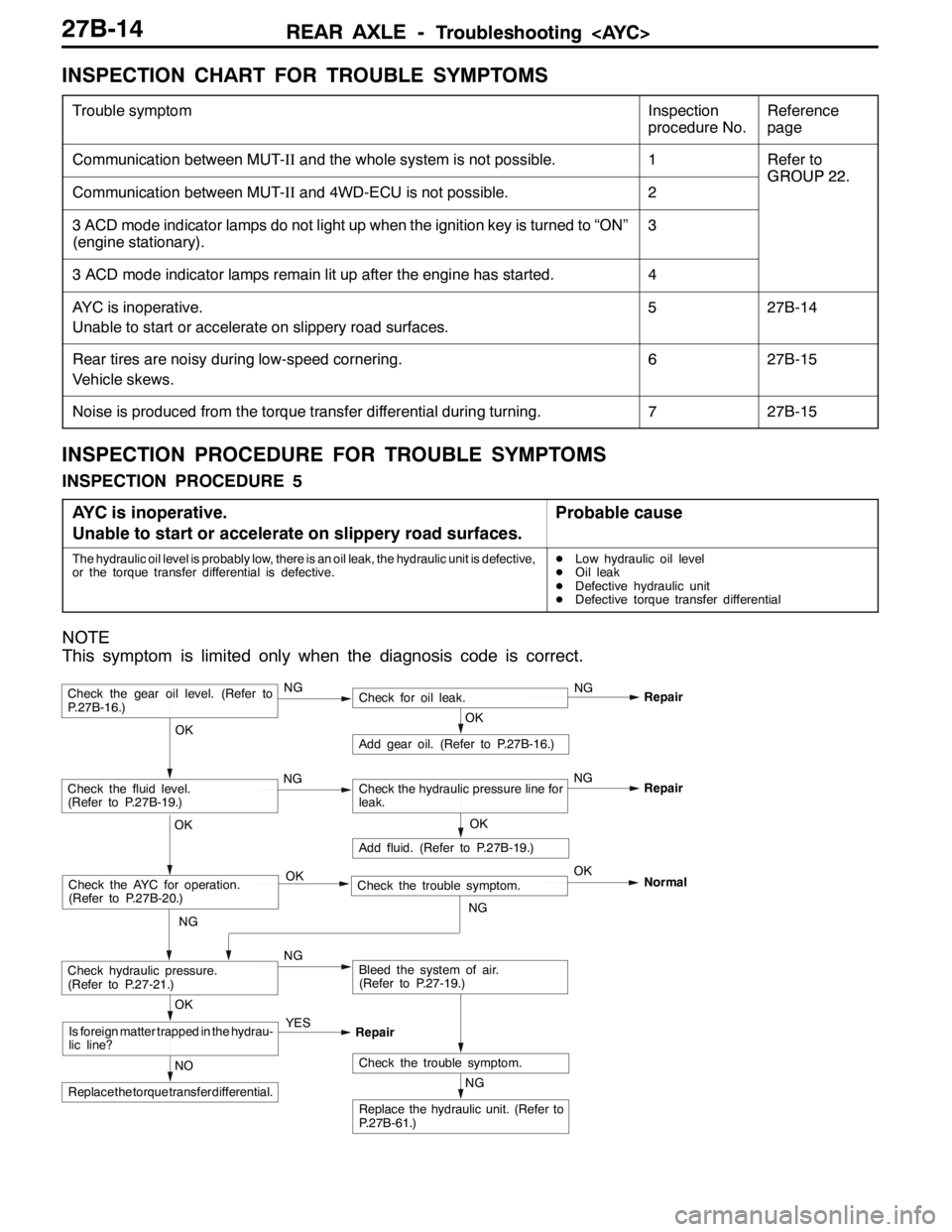
INSPECTION PROCEDURE 5
AYC is inoperative.
Unable to start or accelerate on slippery road surfaces.
Probable cause
The hydraulic oil level is probably low, there is an oil leak, the hydraulic unit is defective,
or the torque transfer differential is defective.DLow hydraulic oil level
DOil leak
DDefective hydraulic unit
DDefective torque transfer differential
NOTE
This symptom is limited only when the diagnosis code is correct.
NG
Replace the hydraulic unit. (Refer to
P.27B-61.)
NG
Add fluid. (Refer to P.27B-19.)
OKRepair
Check the trouble symptom.NO
Replace the torque transfer differential.
OK
Is foreign matter trapped in the hydrau-
lic line?YES
Repair
OK
Check the fluid level.
(Refer to P.27B-19.)Check the hydraulic pressure line for
leak.
OK
Add gear oil. (Refer to P.27B-16.)
OK
Check hydraulic pressure.
(Refer to P.27-21.)NGBleed the system of air.
(Refer to P.27-19.)
Check the gear oil level. (Refer to
P.27B-16.)NGCheck for oil leak.NG
Repair
Check the AYC for operation.
(Refer to P.27B-20.)Check the trouble symptom. OKOK
NGNormal
NGNG
Page 966 of 1449

REAR AXLE -On-vehicle Service27B-20
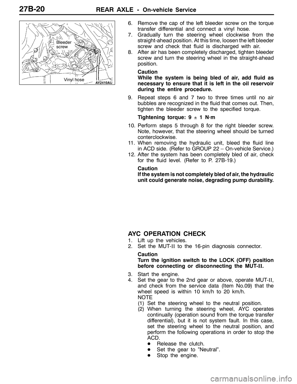
6. Remove the cap of the left bleeder screw on the torque
transfer differential and connect a vinyl hose.
7. Gradually turn the steering wheel clockwise from the
straight-ahead position. At this time, loosen the left bleeder
screw and check that fluid is discharged with air.
8. After air has been completely discharged, tighten bleeder
screw and turn the steering wheel in the straight-ahead
position.
Caution
While the system is being bled of air, add fluid as
necessary to ensure that it is left in the oil reservoir
during the entire procedure.
9. Repeat steps 6 and 7 two to three times until no air
bubbles are recognized in the fluid that comes out. Then,
tighten the bleeder screw to the specified torque.
Tightening torque: 9±1 N·m
10. Perform steps 5 through 8 for the right bleeder screw.
Note, however, that the steering wheel should be turned
conterclockwise.
11. When removing the hydraulic unit, bleed the fluid line
in ACD side. (Refer to GROUP 22 – On-vehicle Service.)
12. After the system has been completely bled of air, check
for the fluid level. (Refer to P. 27B-19.)
Caution
If the system is not completely bled of air, the hydraulic
unit could generate noise, degrading pump durability.
AYC OPERATION CHECK
1. Lift up the vehicles.
2. Set the MUT-IIto the 16-pin diagnosis connector.
Caution
Turn the ignition switch to the LOCK (OFF) position
before connecting or disconnecting the MUT-II.
3. Start the engine.
4. Set the gear to the 2nd gear or above, operate MUT-II,
and check from the service data (Item No.09) that the
wheel speed is within 10 km/h to 20 km/h.
NOTE
(1) Set the steering wheel to the neutral position.
(2) When turning the steering wheel, AYC operates
continually (operation sound from the torque transfer
differential), but it is not system fault. In this case,
set the steering wheel to the neutral position, and
perform the following operations in order to stop the
ACD.
DRelease the clutch.
DSet the gear to ”Neutral”.
DStop the engine.
Bleeder
screw
Vinyl hose