Page 788 of 1449
ENGINE AND EMISSION CONTROL -Emission Control System17-18
CANISTER
REMOVAL AND INSTALLATION
Pre-removal and Post-installation Operation
DAir Pipe C, Air Hose D Removal and Installation (Refer to GROUP 15 - Inter Cooler.)
DBattery and Battery Tray Removal and Installation
DAir Cleaner Assembly Removal and Installation (Refer to GROUP 15 - Air Cleaner.)
1 2
3 4
5
67
89
Canister removal steps
1. Purge hose
2. Check valve
3. Vapor hose
4. Vent connector
5. Vapor hose6. Hose clamp
7. Canister
8. Fuel high pressure hose
9. Canister bracket assembly
Page 789 of 1449
ENGINE AND EMISSION CONTROL -Emission Control System17-19
CATALYTIC CONVERTER
GENERAL INFORMATION
The three-way catalytic converter, together with
the closed loop air-fuel ratio control based on the
oxygen sensor signal, oxidizes carbon monoxides
(CO) and hydrocarbons (HC) and reduces nitrogen
oxides (NOx).When the mixture is controlled at stoichiometric
air-fuel ratio, the three-way catalytic converter
provides the highest purification against the three
constituents, namely, CO, HC and NOx.
REMOVAL AND INSTALLATION
Pre-removal and Post-installation Operation
DUnder Cover Removal and Installation (Refer to GROUP 51 - Front Bumper.)
DCrossmember Bar Removal and Installation (Refer to GROUP 32 - Engine Roll Stopper, Centermember.)
123
49±10N·m
13±2N·m 13±2N·m
59±10N·m
50±5N·m
Removal steps
1. Spring
2. Front exhaust pipe
3. Catalytic converter
Page 795 of 1449
CLUTCH -On-Vehicle Service/Clutch Pedal21A-5
5. Fix the clutch pedal position switch by rotating approx.
quarter turn to clockwise in the position as shown in the
illustration.
6. Connect the connector to the clutch pedal position switch.
7. Check that the engine starts when the clutch is released.
CLUTCH PEDAL
REMOVAL AND INSTALLATION
Post-installation Operation
DClutch Pedal Adjustment (Refer to P.21A-2.)
DClutch Pedal Position Switch Adjustment (Refer to
P.21A-4.)
6713±2 N·m
1
12±2 N·m
8
11
2459
12±2 N·m
67
13±2 N·m
10 8
12 13
3145 910
1112 13
14
Full stroke
position of
clutch pedal
Approx.
3.5 mm
Page 811 of 1449

MANUAL TRANSMISSION -General/General Information/
Service Specification/Lubricants22A-3
GENERAL
OUTLINE OF CHANGE
With the addition of the EVOLUTION-VII, the W5M51 transmission service adjustment procedure has
been set as follows.
GENERAL INFORMATION
ItemsSpecifications
GradeRS, RS IIRS, RS II (With super cross gear)
Transmission modelW5M51
Engine model4G63-DOHC-T/C
Type5-speed, floor-shift
Gear ratio1st2.7852.785
2nd1.9501.950
3rd1.4071.444
4th1.0311.096
5th0.7200.825
Reverse3.4163.416
Final reduction ratio
(Differential gear ratio)4.5294.529
Front limited-slip differential
(Helical-gear type)Not providedProvided
TransferReduction ratio3.3073.307
Limited-slipdifferentialVCU or hydraulic multi plate
clutch (ACD)VCU or hydraulic multi plate
clutch (ACD)
SERVICE SPECIFICATION
ItemStandard value
Hydraulic unit generation oil pressureMPa1.0 - 1.6
LUBRICANTS
ItemSpecified lubricantQuantity L
Transmission oilGear oil SAE 75W-90 or 75W-85W conforming to API GL-42.8
Transfer
oilVehicles without ACD or ve-
hicles without ACD and AYCMITSUBISHI Genuine Gear Oil Part No.8149630 EX,
CASTROL HYPOY LS (GL-5, SAE 90), SHELL-LSD
(GL 5SAE80W90)orequivalent
0.55
Vehicles with ACD or vehicles
with ACD and AYC(GL-5, SAE 80W - 90) or equivalent0.6
FluidPiping between ACD and
hydraulic unitDIA QUEEN ATF SP III0.9
Pipes between ACD and hy-
draulic unit and between AYC
and hydraulic unit1.0
Page 812 of 1449
MANUAL TRANSMISSION - Special Tools22A-4
SPECIAL TOOLS
ToolNumberNameUse
MB991502MUT-IISub as-
semblyDiagnosis code checking
MB991529Diagnosis code
checking harness
MB991348Test harness setGsensor check
MD998330
(including
MD998331)Oil pressure gauge
(3.0 MPa)Hydraulic pressure measurement
MB991705Adapter
MB990635,
MB991113 or
MB991406
Steering linkage
pullerTie rod end and lower disconnection
GENERAL
SERVICE
TOOL
MZ203827Engine lifterSupporting the engine assembly during
removal and installation of the transmission
MB991453Engine hangerat-
tachment set
MB991721Slide hammerOutput shaft removal
Page 813 of 1449

MANUAL TRANSMISSION - Troubleshooting 22A-5
TROUBLESHOOTING
BASIC TROUBLESHOOTING CONDITIONS
Refer to GROUP 00 - How to Use Troubleshooting/Inspection Service Points.
NOTE
Before starting the troubleshooting procedure, make sure that the following items have been checked
okay.
DIs the appropriate steering wheel installed at the center of the steering column shaft correctly?
DAre the tire, wheel size, specifications, air pressure, balance, and wear state normal?
DIs the wheel alignment normal?
DHas the engine, suspension, etc. been remodeled in such a way that it will affect the ACD and AYC
systems?
DIAGNOSIS FUNCTION
READING DIAGNOSIS CODE
Read a diagnosis code by the MUT-IIor ACD mode indicator
lamp. (Refer to GROUP 00 - How to Use Troubleshooting/
Inspection Service Points.)
NOTE
Connect the MUT-IIto the diagnosis connector (16-pin).
ERASING DIAGNOSIS CODES
When using the MUT-II
Connect the MUT-IIto the diagnosis connector (16-pin) and
erase the diagnosis code.
Caution
Turn the ignition switch to the “LOCK”(OFF) position
before connecting or disconnecting the MUT-II.
ACDmode indicator lamp
Page 839 of 1449

MANUAL TRANSMISSION - Troubleshooting 22A-31
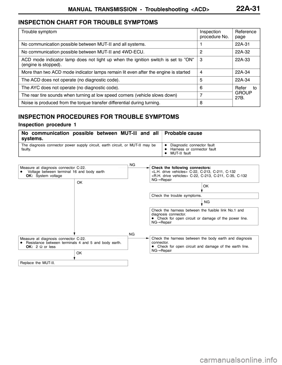
INSPECTION CHART FOR TROUBLE SYMPTOMS
Trouble symptomInspection
procedure No.Reference
page
No communication possible between MUT-IIand all systems.122A-31
No communication possible between MUT-IIand 4WD-ECU.222A-32
ACD mode indicator lamp does not light up when the ignition switch is set to ”ON“
(engine is stopped).322A-33
More than two ACD mode indicator lamps remain lit even after the engine is started422A-34
The ACD does not operate (no diagnostic code).522A-34
The AYC does not operate (no diagnostic code).6Refer to
GROUPThe rear tire sounds when turning at low speed corners (vehicle slows down)7GROUP
27B.
Noise is produced from the torque transfer differential during turning.8
27B.
INSPECTION PROCEDURES FOR TROUBLE SYMPTOMS
Inspection procedure 1
No communication possible between MUT-IIand all
systems.
Probable cause
The diagnosis connector power supply circuit, earth circuit, or MUT-IImay be
faulty.DDiagnostic connector fault
DHarness or connector fault
DMUT-IIfault
OK
NG
NG
Check the harness between the fusible link No.1 and
diagnosis connector.
DCheck for open circuit or damage of the power line.
NG→Repair
OK
Check the trouble symptoms.
Measure at diagnosis connector C-22.
DVoltage between terminal 16 and body earth
OK:System voltageNGCheck the following connectors:
C-22, C-213, C-211, C-132
C-22, C-213, C-211, C-35, C-132
NG→Repair
Check the harness between the body earth and diagnosis
connector.
DCheck for open circuit and damage of the earth line.
NG→Repair
OK
Replace the MUT-II.
Measure at diagnosis connector C-22.
DResistance between terminals 4 and 5 and body earth.
OK:2Ωor less
Page 841 of 1449

MANUAL TRANSMISSION - Troubleshooting 22A-33
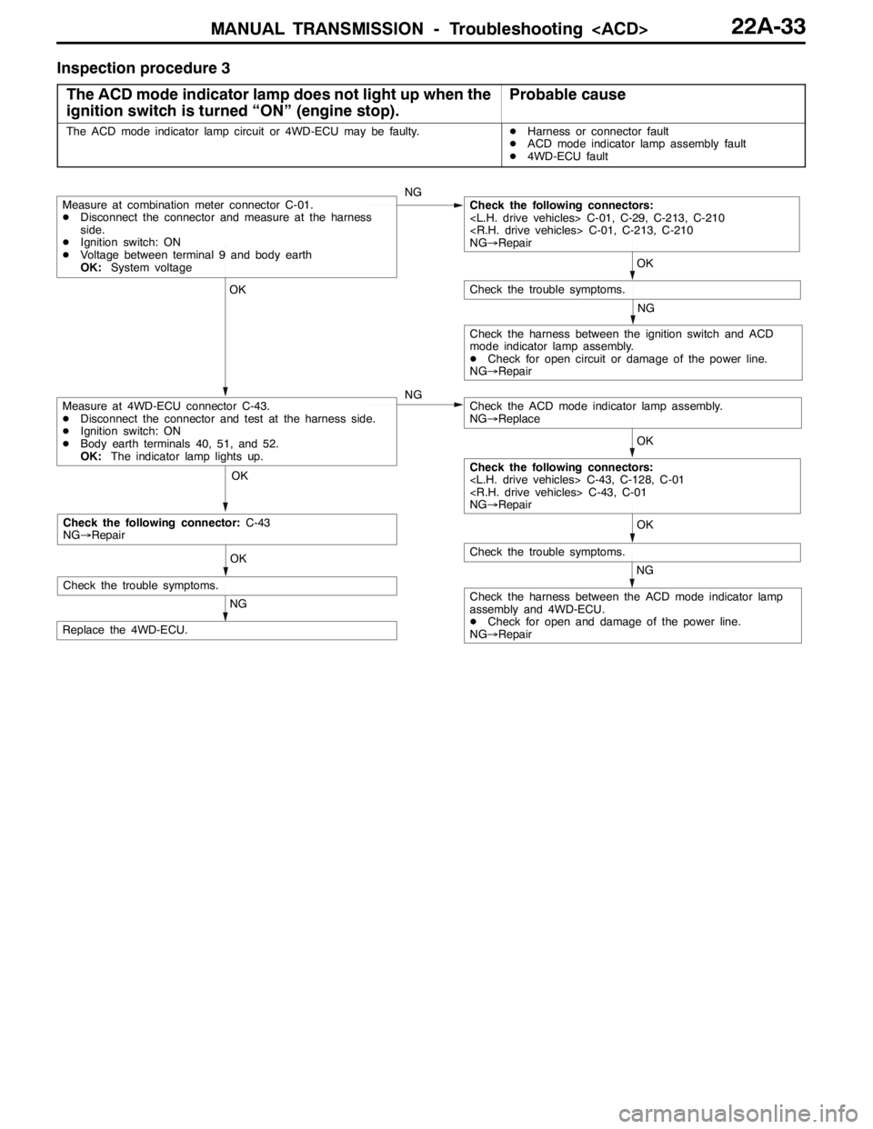
Inspection procedure 3
The ACD mode indicator lamp does not light up when the
ignition switch is turned “ON” (engine stop).
Probable cause
The ACD mode indicator lamp circuit or 4WD-ECU may be faulty.DHarness or connector fault
DACD mode indicator lamp assembly fault
D4WD-ECU fault
OK OK OKOK
NG
OK
NG
NG
NG
Check the harness between the ACD mode indicator lamp
assembly and 4WD-ECU.
DCheck for open and damage of the power line.
NG→Repair
Replace the 4WD-ECU.
Measure at 4WD-ECU connector C-43.
DDisconnect the connector and test at the harness side.
DIgnition switch: ON
DBody earth terminals 40, 51, and 52.
OK:The indicator lamp lights up.
Check the trouble symptoms.
Measure at combination meter connector C-01.
DDisconnect the connector and measure at the harness
side.
DIgnition switch: ON
DVoltage between terminal 9 and body earth
OK:System voltageCheck the following connectors:
C-01, C-29, C-213, C-210
C-01, C-213, C-210
NG→Repair
Check the trouble symptoms.
Check the ACD mode indicator lamp assembly.
NG→Replace
Check the harness between the ignition switch and ACD
mode indicator lamp assembly.
DCheck for open circuit or damage of the power line.
NG→Repair
Check the following connectors:
C-43, C-128, C-01
C-43, C-01
NG→Repair
OK
NG
Check the trouble symptoms.
Check the following connector:C-43
NG→Repair