Page 519 of 1449

ENGINE OVERHAUL -Crankshaft and Cylinder Block11B-65
INSTALLATION SERVICE POINTS
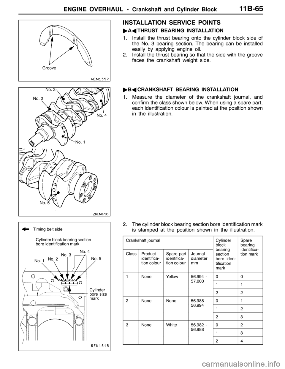
"AATHRUST BEARING INSTALLATION
1. Install the thrust bearing onto the cylinder block side of
the No. 3 bearing section. The bearing can be installed
easily by applying engine oil.
2. Install the thrust bearing so that the side with the groove
faces the crankshaft weight side.
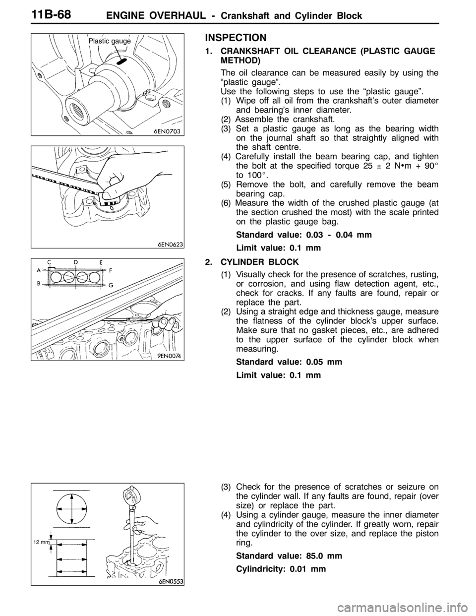
"BACRANKSHAFT BEARING INSTALLATION
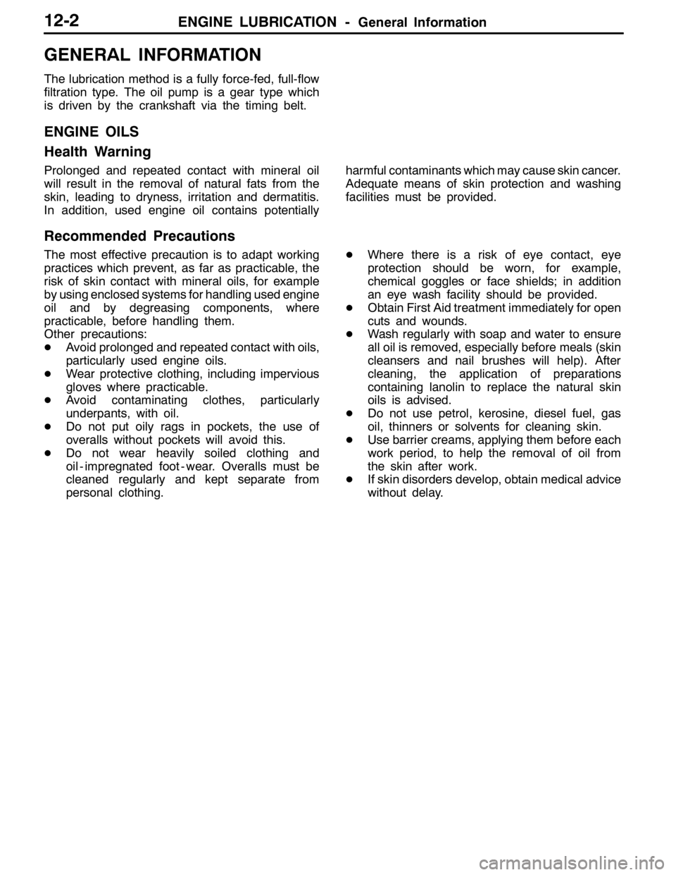
1. Measure the diameter of the crankshaft journal, and
confirm the class shown below. When using a spare part,
each identification colour is painted at the position shown
in the illustration.
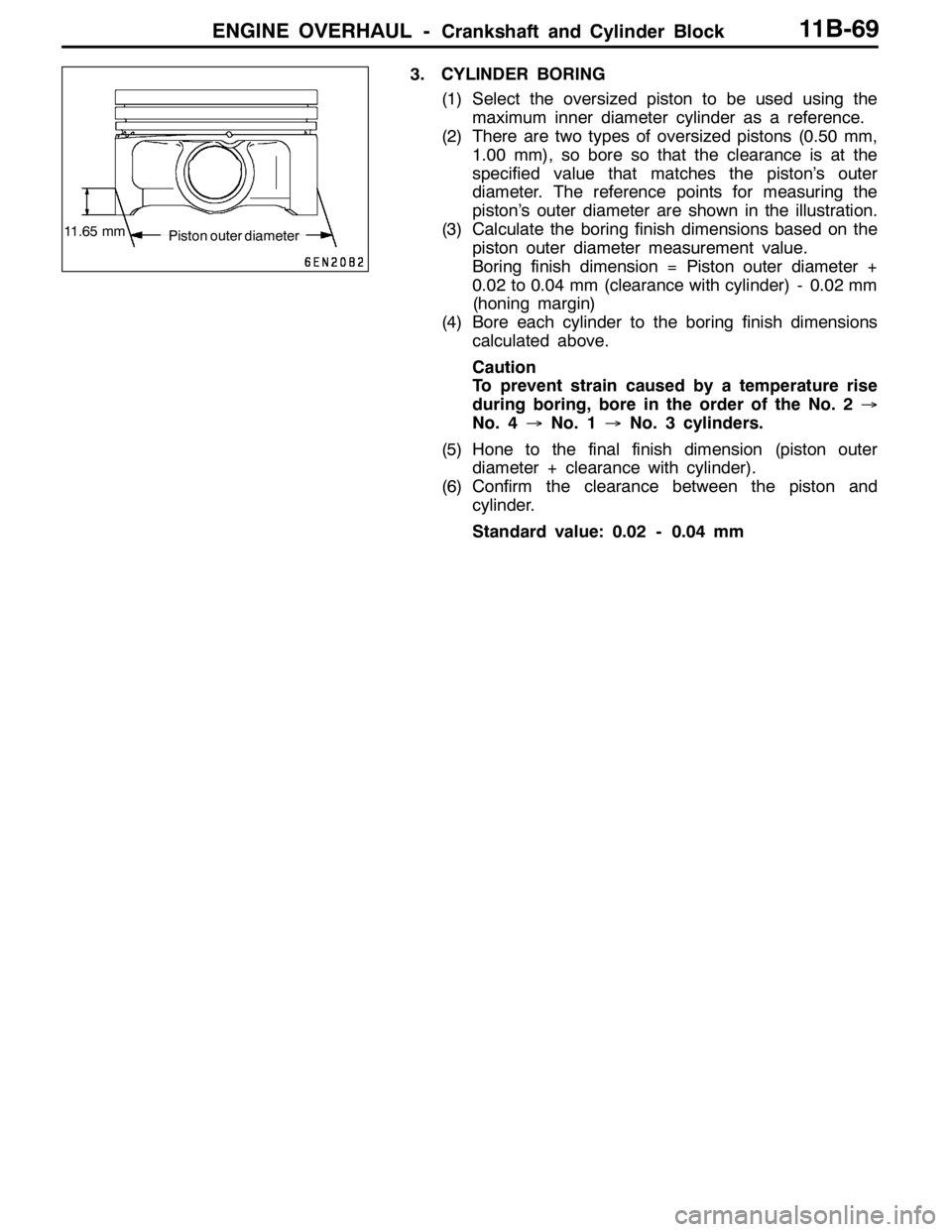
2. The cylinder block bearing section bore identification mark
is stamped at the position shown in the illustration.
Crankshaft journalCylinder
block
bearing
Spare
bearing
identificaClassProduct
identifica-
tion colourSpare part
identifica-
tion colourJournal
diameter
mmbearing
section
bore iden-
tification
markidentifica-
tion mark
1NoneYellow56.994 -57 0000057.00011
22
2NoneNone56.988 -56 9940156.99412
23
3NoneWhite56.982 -56 9880256.98813
24
Groove
No. 2
No. 1No. 4
No. 5No. 3
Timing belt side
Cylinder block bearing section
bore identification mark
No. 1No. 2No. 3No. 4
No. 5
Cylinder
bore size
mark
Page 520 of 1449
![MITSUBISHI LANCER EVOLUTION 2007 Service Repair Manual ENGINE OVERHAUL -Crankshaft and Cylinder Block11B-66
3. Select the bearing from the above table according to
the identification confirmed in steps 1 and 2.
[Example of selecting bearing]
(1) If the me MITSUBISHI LANCER EVOLUTION 2007 Service Repair Manual ENGINE OVERHAUL -Crankshaft and Cylinder Block11B-66
3. Select the bearing from the above table according to
the identification confirmed in steps 1 and 2.
[Example of selecting bearing]
(1) If the me](/manual-img/19/57084/w960_57084-519.png)
ENGINE OVERHAUL -Crankshaft and Cylinder Block11B-66
3. Select the bearing from the above table according to
the identification confirmed in steps 1 and 2.
[Example of selecting bearing]
(1) If the measured outer diameter of the crankshaft
journal is 57.000 mm, Class 1 applies, and the
identification colour is yellow.
(2) If the cylinder block bearing bore identification mark
is 0, select identification mark 0 in consideration of
step (1).
4. Install the grooved bearing on the cylinder block side.
5. Install the bearing with no oil groove onto the beam bearing
cap side.
"CABEAM BEARING CAP/BEARING CAP BOLT
INSTALLATION
1. Install the beam bearing cap with the arrow facing the
timing belt side.
2. Before installing the bearing cap bolt, confirm that the
bolt’s underhead length is less than the limit value.
Replace the bolt if it exceeds the limit value.
Limit value: 71.1 mm
3. Apply engine oil on the bolt threads and bolt surface.
4. Following the tightening order, tighten the bearing cap
bolt at 25±2N•m.
5. Make paint marks on the bolt head.
6. Using the position of the mark painted on the bolt head
as reference, make paint marks on the seat surface at
the 90_to 100_positions in the tightening direction.
7. Following the tightening order, tighten the bolt by 90_
to 100_, and confirm that the paint marks made on the
bolt and seat surface match.
Caution
(1) If the tightening angle is less than 90_, the
connection performance may not be attained, so
take special care when tightening.
(2) If the tightening angle exceeds 100_, completely
loosen the nut, and start again from step 1.Crankshaft bearing side
identification mark position
Identification
mark
Groove
Upper bearing
Lower bearing
Underhead length
Arrow
84159
732610
Paint marksPaint marks
90°- 100°
Page 521 of 1449
ENGINE OVERHAUL -Crankshaft and Cylinder Block11B-67
8. After installing the beam bearing cap, inspect the end
play of the crankshaft. If the end play exceeds the limit
value, replace the crankshaft bearing.
Standard value: 0.05 - 0.25 mm
Limit value: 0.4 mm
"DAREAR OIL SEAL INSTALLATION
Press in the rear oil seal using the special tool.
"EAREAR OIL SEAL CASE INSTALLATION
1. Apply form-in-place gasket onto the rear oil seal case
at the position shown in the illustration.
Form-in-place gasket
Specified gasket:
Mitsubishi Genuine Part No. MD970389 or
equivalent
Caution
Evenly squeeze out the form-in-place gasket so that
it is not insufficient or excessive.
2. Apply an appropriate amount of engine oil on the entire
periphery of the oil seal lip, and install on the cylinder
block.
MB990938
MD998776
Page 522 of 1449

ENGINE OVERHAUL -Crankshaft and Cylinder Block11B-68
INSPECTION
1. CRANKSHAFT OIL CLEARANCE (PLASTIC GAUGE
METHOD)
The oil clearance can be measured easily by using the
“plastic gauge”.
Use the following steps to use the “plastic gauge”.
(1) Wipe off all oil from the crankshaft’s outer diameter
and bearing’s inner diameter.
(2) Assemble the crankshaft.
(3) Set a plastic gauge as long as the bearing width
on the journal shaft so that straightly aligned with
the shaft centre.
(4) Carefully install the beam bearing cap, and tighten
the bolt at the specified torque 25±2N•m+90_
to 100_.
(5) Remove the bolt, and carefully remove the beam
bearing cap.
(6) Measure the width of the crushed plastic gauge (at
the section crushed the most) with the scale printed
on the plastic gauge bag.
Standard value: 0.03 - 0.04 mm
Limit value: 0.1 mm
2. CYLINDER BLOCK
(1) Visually check for the presence of scratches, rusting,
or corrosion, and using flaw detection agent, etc.,
check for cracks. If any faults are found, repair or
replace the part.
(2) Using a straight edge and thickness gauge, measure
the flatness of the cylinder block’s upper surface.
Make sure that no gasket pieces, etc., are adhered
to the upper surface of the cylinder block when
measuring.
Standard value: 0.05 mm
Limit value: 0.1 mm
(3) Check for the presence of scratches or seizure on
the cylinder wall. If any faults are found, repair (over
size) or replace the part.
(4) Using a cylinder gauge, measure the inner diameter
and cylindricity of the cylinder. If greatly worn, repair
the cylinder to the over size, and replace the piston
ring.
Standard value: 85.0 mm
Cylindricity: 0.01 mm
Plastic gauge
12 mm
Page 523 of 1449

ENGINE OVERHAUL -Crankshaft and Cylinder Block11B-69
3. CYLINDER BORING
(1) Select the oversized piston to be used using the
maximum inner diameter cylinder as a reference.
(2) There are two types of oversized pistons (0.50 mm,
1.00 mm), so bore so that the clearance is at the
specified value that matches the piston’s outer
diameter. The reference points for measuring the
piston’s outer diameter are shown in the illustration.
(3) Calculate the boring finish dimensions based on the
piston outer diameter measurement value.
Boring finish dimension = Piston outer diameter +
0.02 to 0.04 mm (clearance with cylinder) - 0.02 mm
(honing margin)
(4) Bore each cylinder to the boring finish dimensions
calculated above.
Caution
To prevent strain caused by a temperature rise
during boring, bore in the order of the No. 2→
No. 4→No. 1→No. 3 cylinders.
(5) Hone to the final finish dimension (piston outer
diameter + clearance with cylinder).
(6) Confirm the clearance between the piston and
cylinder.
Standard value: 0.02 - 0.04 mm
Piston outer diameter 11.65 mm
Page 525 of 1449
12-1
ENGINE
LUBRICATION
CONTENTS
GENERAL INFORMATION 2..................
SERVICE SPECIFICATIONS 3.................
SEALANT 3..................................
LUBRICANTS 3..............................
SPECIAL TOOL 3............................ON-VEHICLE SERVICE 4.....................
Engine Oil Check 4............................
Engine Oil Replacement 4.......................
Oil Filter Replacement 5........................
Oil Pressure Check 5..........................
ENGINE OIL COOLER 7......................
Page 526 of 1449

ENGINE LUBRICATION -General Information12-2
GENERAL INFORMATION
The lubrication method is a fully force-fed, full-flow
filtration type. The oil pump is a gear type which
is driven by the crankshaft via the timing belt.
ENGINE OILS
Health Warning
Prolonged and repeated contact with mineral oil
will result in the removal of natural fats from the
skin, leading to dryness, irritation and dermatitis.
In addition, used engine oil contains potentiallyharmful contaminants which may cause skin cancer.
Adequate means of skin protection and washing
facilities must be provided.
Recommended Precautions
The most effective precaution is to adapt working
practices which prevent, as far as practicable, the
risk of skin contact with mineral oils, for example
by using enclosed systems for handling used engine
oil and by degreasing components, where
practicable, before handling them.
Other precautions:
DAvoid prolonged and repeated contact with oils,
particularly used engine oils.
DWear protective clothing, including impervious
gloves where practicable.
DAvoid contaminating clothes, particularly
underpants, with oil.
DDo not put oily rags in pockets, the use of
overalls without pockets will avoid this.
DDo not wear heavily soiled clothing and
oil - impregnated foot - wear. Overalls must be
cleaned regularly and kept separate from
personal clothing.DWhere there is a risk of eye contact, eye
protection should be worn, for example,
chemical goggles or face shields; in addition
an eye wash facility should be provided.
DObtain First Aid treatment immediately for open
cuts and wounds.
DWash regularly with soap and water to ensure
all oil is removed, especially before meals (skin
cleansers and nail brushes will help). After
cleaning, the application of preparations
containing lanolin to replace the natural skin
oils is advised.
DDo not use petrol, kerosine, diesel fuel, gas
oil, thinners or solvents for cleaning skin.
DUse barrier creams, applying them before each
work period, to help the removal of oil from
the skin after work.
DIf skin disorders develop, obtain medical advice
without delay.
Page 527 of 1449
ENGINE LUBRICATION -Service Specifications/Sealant/Lubricants/Special Tool12-3
SERVICE SPECIFICATIONS
ItemsStandard value
Oil pressure kPaat idle29 or more
at 3,500 r/min294 - 686
SEALANT
ItemsSpecified sealantRemark
Oil pressure switch3M ATD Part No. 8660 or equivalentSemi-drying sealant
LUBRICANTS
ItemsSpecifications
Engine oil ACEA classificationFor EuropeA1, A2, A3
Engine oil API classificationFor EuropeSG or higher
For General ExportSE or higher
Engine oil quantity LOil filter0.3
Oil cooler0.3
Total5.1
SPECIAL TOOL
ToolNumberNameUse
MD998054Oil pressure switch
wrenchRemoval and installation of oil pressure switch