2007 MITSUBISHI LANCER EVOLUTION engine
[x] Cancel search: enginePage 548 of 1449
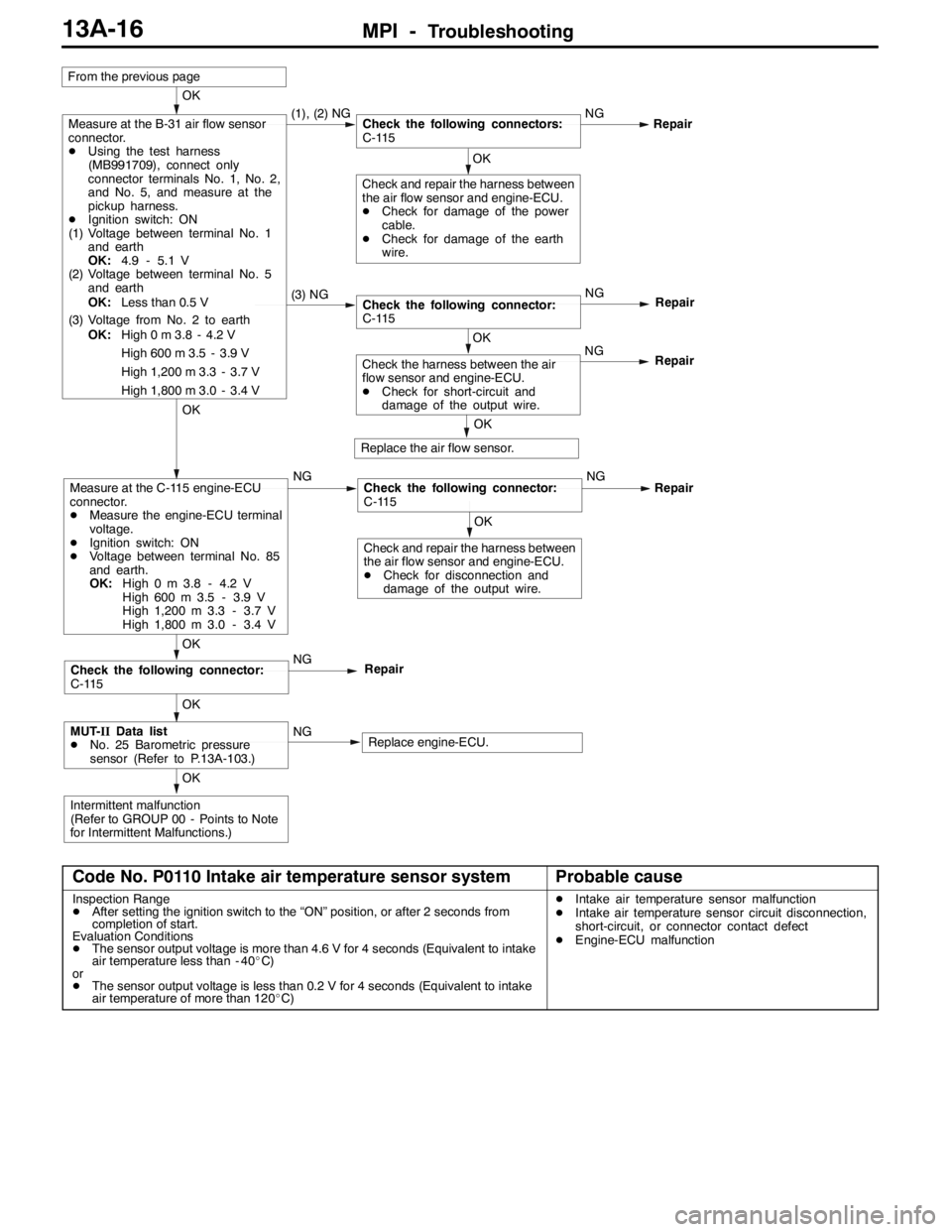
MPI -Troubleshooting13A-16
OK
Intermittent malfunction
(Refer to GROUP 00 - Points to Note
for Intermittent Malfunctions.)
OK
MUT-IIData list
DNo. 25 Barometric pressure
sensor (Refer to P.13A-103.)NGReplace engine-ECU.
OK
Check the following connector:
C-115NG
Repair
OK
Check and repair the harness between
the air flow sensor and engine-ECU.
DCheck for disconnection and
damage of the output wire.
OK
Measure at the C-115 engine-ECU
connector.
DMeasure the engine-ECU terminal
voltage.
DIgnition switch: ON
DVoltage between terminal No. 85
and earth.
OK:High 0 m 3.8 - 4.2 V
High 600 m 3.5 - 3.9 V
High 1,200 m 3.3 - 3.7 V
High 1,800 m 3.0 - 3.4 VNGCheck the following connector:
C-115NGRepair
OK
Replace the air flow sensor.
OK
Check the harness between the air
flow sensor and engine-ECU.
DCheck for short-circuit and
damage of the output wire.NG
Repair
(3) NGCheck the following connector:
C-115NG
Repair
OK
Check and repair the harness between
the air flow sensor and engine-ECU.
DCheck for damage of the power
cable.
DCheck for damage of the earth
wire.
OK
Measure at the B-31 air flow sensor
connector.
DUsing the test harness
(MB991709), connect only
connector terminals No. 1, No. 2,
and No. 5, and measure at the
pickup harness.
DIgnition switch: ON
(1) Voltage between terminal No. 1
and earth
OK:4.9 - 5.1 V
(2) Voltage between terminal No. 5
and earth
OK:Less than 0.5 V
(3) Voltage from No. 2 to earth
OK:High 0 m 3.8 - 4.2 V
High 600 m 3.5 - 3.9 V
High 1,200 m 3.3 - 3.7 V
High 1,800 m 3.0 - 3.4 V(1), (2) NGCheck the following connectors:
C-115NGRepair
From the previous page
Code No. P0110 Intake air temperature sensor systemProbable cause
Inspection Range
DAfter setting the ignition switch to the “ON” position, or after 2 seconds from
completion of start.
Evaluation Conditions
DThe sensor output voltage is more than 4.6 V for 4 seconds (Equivalent to intake
air temperature less than - 40_C)
or
DThe sensor output voltage is less than 0.2 V for 4 seconds (Equivalent to intake
air temperature of more than 120_C)DIntake air temperature sensor malfunction
DIntake air temperature sensor circuit disconnection,
short-circuit, or connector contact defect
DEngine-ECU malfunction
Page 549 of 1449
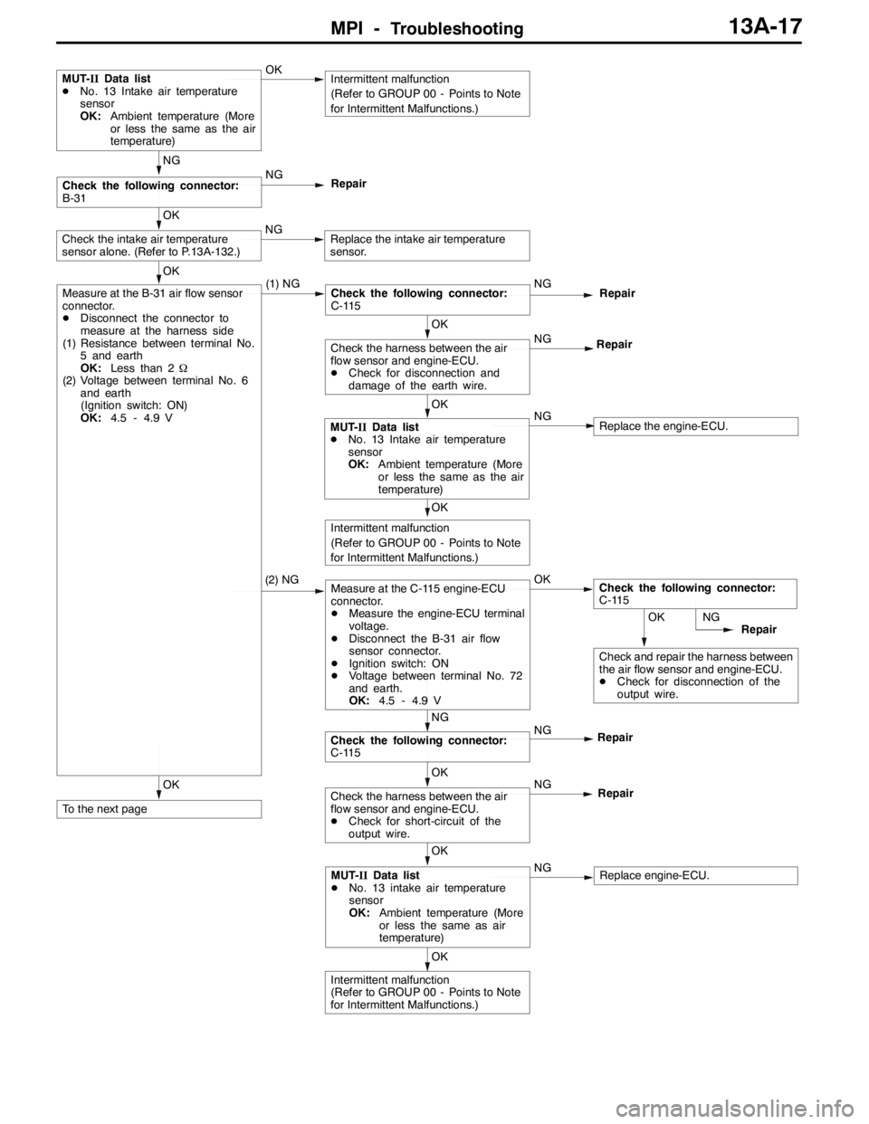
MPI -Troubleshooting13A-17
OK
Check the intake air temperature
sensor alone. (Refer to P.13A-132.)NGReplace the intake air temperature
sensor.
OK
Intermittent malfunction
(Refer to GROUP 00 - Points to Note
for Intermittent Malfunctions.)
OK
To the next page
OK
Intermittent malfunction
(Refer to GROUP 00 - Points to Note
for Intermittent Malfunctions.)
OK
MUT-IIData list
DNo. 13 intake air temperature
sensor
OK:Ambient temperature (More
or less the same as air
temperature)NGReplace engine-ECU.
OK
Check the harness between the air
flow sensor and engine-ECU.
DCheck for short-circuit of the
output wire.NG
Repair
OK
Check and repair the harness between
the air flow sensor and engine-ECU.
DCheck for disconnection of the
output wire.NG
Repair
NG
Check the following connector:
C-115NG
Repair
(2) NGMeasure at the C-115 engine-ECU
connector.
DMeasure the engine-ECU terminal
voltage.
DDisconnect the B-31 air flow
sensor connector.
DIgnition switch: ON
DVoltage between terminal No. 72
and earth.
OK:4.5 - 4.9 VOKCheck the following connector:
C-115
OK
MUT-IIData list
DNo. 13 Intake air temperature
sensor
OK:Ambient temperature (More
or less the same as the air
temperature)NGReplace the engine-ECU.
OK
Check the harness between the air
flow sensor and engine-ECU.
DCheck for disconnection and
damage of the earth wire.NG
Repair
OK
Measure at the B-31 air flow sensor
connector.
DDisconnect the connector to
measure at the harness side
(1) Resistance between terminal No.
5 and earth
OK:Less than 2Ω
(2) Voltage between terminal No. 6
and earth
(Ignition switch: ON)
OK:4.5 - 4.9 V(1) NGCheck the following connector:
C-115NGRepair
NG
Check the following connector:
B-31NG
Repair
MUT-IIData list
DNo. 13 Intake air temperature
sensor
OK:Ambient temperature (More
or less the same as the air
temperature)OKIntermittent malfunction
(Refer to GROUP 00 - Points to Note
for Intermittent Malfunctions.)
Page 550 of 1449
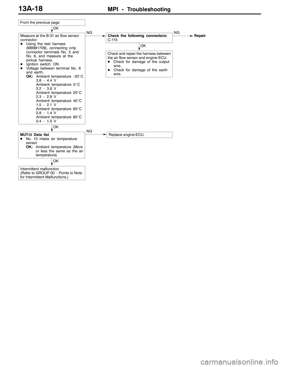
MPI -Troubleshooting13A-18
OK
Intermittent malfunction
(Refer to GROUP 00 - Points to Note
for Intermittent Malfunctions.)
OK
MUT-IIData list
DNo. 13 intake air temperature
sensor
OK:Ambient temperature (More
or less the same as the air
temperature)NGReplace engine-ECU.
OK
Check and repair the harness between
the air flow sensor and engine-ECU.
DCheck for damage of the output
wire.
DCheck for damage of the earth
wire.
OK
Measure at the B-31 air flow sensor
connector.
DUsing the test harness
(MB991709), connecting only
connector terminals No. 5 and
No. 6, and measure at the
pickup harness.
DIgnition switch: ON
DVoltage between terminal No. 6
and earth.
OK:Ambient temperature - 20_C
3.8 - 4.4 V
Ambient temperature 0_C
3.2 - 3.8 V
Ambient temperature 20_C
2.3 - 2.9 V
Ambient temperature 40_C
1.5 - 2.1 V
Ambient temperature 60_C
0.8 - 1.4 V
Ambient temperature 80_C
0.4 - 1.0 VNGCheck the following connectors:
C-115NGRepair
From the previous page
Page 551 of 1449
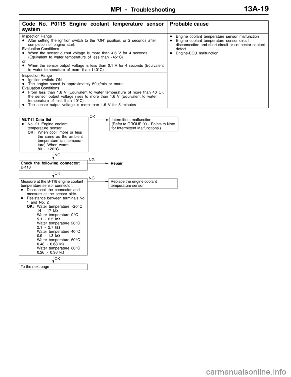
MPI -Troubleshooting13A-19
Code No. P0115 Engine coolant temperature sensor
systemProbable cause
Inspection Range
DAfter setting the ignition switch to the “ON” position, or 2 seconds after
completion of engine start.
Evaluation Conditions
DWhen the sensor output voltage is more than 4.6 V for 4 seconds
(Equivalent to water temperature of less than - 45_C)
or
DWhen the sensor output voltage is less than 0.1 V for 4 seconds (Equivalent
to water temperature of more than 140_C)DEngine coolant temperature sensor malfunction
DEngine coolant temperature sensor circuit
disconnection and short-circuit or connector contact
defect
DEngine-ECU malfunction
Inspection Range
DIgnition switch: ON
DThe engine speed is approximately 50 r/min or more.
Evaluation Conditions
DFrom less than 1.6 V (Equivalent to water temperature of more than 40_C),
the sensor output voltage rises to more than 1.6 V (Equivalent to water
temperature of less than 40_C)
DThe sensor output voltage is more than 1.6 V for 5 minutes
OK
To the next page
OK
Measure at the B-118 engine coolant
temperature sensor connector.
DDisconnect the connector and
measure at the sensor side.
DResistance between terminals No.
1 and No. 2
OK:Water temperature - 20_C
14 - 17 kΩ
Water temperature 0_C
5.1 - 6.5 kΩ
Water temperature 20_C
2.1 - 2.7 kΩ
Water temperature 40_C
0.9 - 1.3 kΩ
Water temperature 60_C
0.48 - 0.68 kΩ
Water temperature 80_C
0.26 - 0.36 kΩNGReplace the engine coolant
temperature sensor.
NG
Check the following connector:
B-118NG
Repair
MUT-IIData list
DNo. 21 Engine coolant
temperature sensor
OK:When cool, more or less
the same as the ambient
temperature (air tempera-
ture) When warm
80 - 120_COKIntermittent malfunction
(Refer to GROUP 00 - Points to Note
for Intermittent Malfunctions.)
Page 552 of 1449
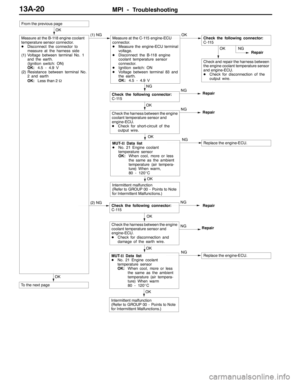
MPI -Troubleshooting13A-20
OK
To the next page
OK
Intermittent malfunction
(Refer to GROUP 00 - Points to Note
for Intermittent Malfunctions.)
OK
MUT-IIData list
DNo. 21 Engine coolant
temperature sensor
OK:When cool, more or less
the same as the ambient
temperature (air tempera-
ture) When warm
80 - 120_CNGReplace the engine-ECU.
OK
Check the harness between the engine
coolant temperature sensor and
engine-ECU.
DCheck for disconnection and
damage of the earth wire.NG
Repair
Check the following connector:
C-115NGRepair (2) NG
OK
Intermittent malfunction
(Refer to GROUP 00 - Points to Note
for Intermittent Malfunctions.)
OK
MUT-IIData list
DNo. 21 Engine coolant
temperature sensor
OK:When cool, more or less
the same as the ambient
temperature (air tempera-
ture) When warm,
80 - 120_CNGReplace the engine-ECU.
OK
Check the harness between the engine
coolant temperature sensor and
engine-ECU.
DCheck for short-circuit of the
output wire.NG
Repair
NG
Check the following connector:
C-115NG
Repair
OK
Check and repair the harness between
the engine coolant temperature sensor
and engine-ECU.
DCheck for disconnection of the
output wire.NG
Repair
OK
Measure at the B-118 engine coolant
temperature sensor connector.
DDisconnect the connector to
measure at the harness side
(1) Voltage between terminal No. 1
and the earth.
(Ignition switch: ON)
OK:4.5 - 4.9 V
(2) Resistance between terminal No.
2 and earth
OK:Less than 2Ω(1) NGMeasure at the C-115 engine-ECU
connector.
DMeasure the engine-ECU terminal
voltage.
DDisconnect the B-118 engine
coolant temperature sensor
connector.
DIgnition switch: ON
DVoltage between terminal 83 and
the earth.
OK:4.5 - 4.9 VOKCheck the following connector:
C-115
From the previous page
Page 553 of 1449
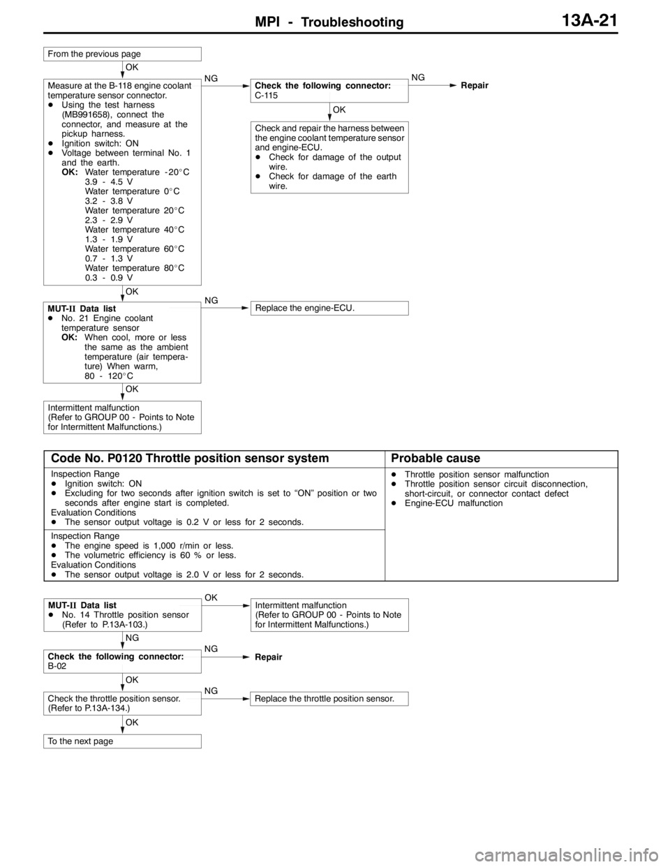
MPI -Troubleshooting13A-21
OK
Intermittent malfunction
(Refer to GROUP 00 - Points to Note
for Intermittent Malfunctions.)
OK
MUT-IIData list
DNo. 21 Engine coolant
temperature sensor
OK:When cool, more or less
the same as the ambient
temperature (air tempera-
ture) When warm,
80 - 120_CNGReplace the engine-ECU.
OK
Check and repair the harness between
the engine coolant temperature sensor
and engine-ECU.
DCheck for damage of the output
wire.
DCheck for damage of the earth
wire.
OK
Measure at the B-118 engine coolant
temperature sensor connector.
DUsing the test harness
(MB991658), connect the
connector, and measure at the
pickup harness.
DIgnition switch: ON
DVoltage between terminal No. 1
and the earth.
OK:Water temperature - 20_C
3.9 - 4.5 V
Water temperature 0_C
3.2 - 3.8 V
Water temperature 20_C
2.3 - 2.9 V
Water temperature 40_C
1.3 - 1.9 V
Water temperature 60_C
0.7 - 1.3 V
Water temperature 80_C
0.3 - 0.9 VNGCheck the following connector:
C-115NG
Repair
From the previous page
Code No. P0120 Throttle position sensor systemProbable cause
Inspection Range
DIgnition switch: ON
DExcluding for two seconds after ignition switch is set to “ON” position or two
seconds after engine start is completed.
Evaluation Conditions
DThe sensor output voltage is 0.2 V or less for 2 seconds.DThrottle position sensor malfunction
DThrottle position sensor circuit disconnection,
short-circuit, or connector contact defect
DEngine-ECU malfunction
Inspection Range
DThe engine speed is 1,000 r/min or less.
DThe volumetric efficiency is 60 % or less.
Evaluation Conditions
DThe sensor output voltage is 2.0 V or less for 2 seconds.
OK
To the next page
OK
Check the throttle position sensor.
(Refer to P.13A-134.)NGReplace the throttle position sensor.
NG
Check the following connector:
B-02NG
Repair
MUT-IIData list
DNo. 14 Throttle position sensor
(Refer to P.13A-103.)OKIntermittent malfunction
(Refer to GROUP 00 - Points to Note
for Intermittent Malfunctions.)
Page 554 of 1449
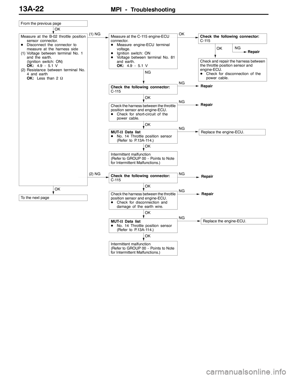
MPI -Troubleshooting13A-22
OK
To the next page
OK
Intermittent malfunction
(Refer to GROUP 00 - Points to Note
for Intermittent Malfunctions.)
OK
MUT-IIData list
DNo. 14 Throttle position sensor
(Refer to P.13A-114.)NGReplace the engine-ECU.
OK
Check the harness between the throttle
position sensor and engine-ECU.
DCheck for disconnection and
damage of the earth wire.NG
Repair
Check the following connector:
C-115NGRepair (2) NG
OK
Intermittent malfunction
(Refer to GROUP 00 - Points to Note
for Intermittent Malfunctions.)
OK
MUT-IIData list
DNo. 14 Throttle position sensor
(Refer to P.13A-114.)NGReplace the engine-ECU.
OK
Check the harness between the throttle
position sensor and engine-ECU.
DCheck for short-circuit of the
power cable.NG
Repair
NG
Check the following connector:
C-115NG
Repair
OK
Check and repair the harness between
the throttle position sensor and
engine-ECU.
DCheck for disconnection of the
power cable.NG
Repair
From the previous page
OK
Measure at the B-02 throttle position
sensor connector.
DDisconnect the connector to
measure at the harness side
(1) Voltage between terminal No. 1
and the earth.
(Ignition switch: ON)
OK:4.9 - 5.1 V
(2) Resistance between terminal No.
4 and earth
OK:Less than 2Ω(1) NGMeasure at the C-115 engine-ECU
connector.
DMeasure engine-ECU terminal
voltage.
DIgnition switch: ON
DVoltage between terminal No. 81
and earth.
OK:4.9 - 5.1 VOKCheck the following connector:
C-115
Page 555 of 1449
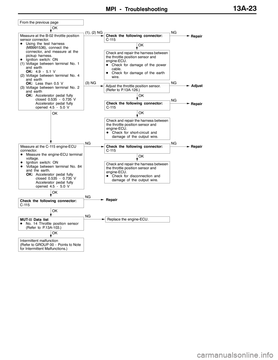
MPI -Troubleshooting13A-23
(3) NGAdjust the throttle position sensor.
(Refer to P.13A-126.)NG
Adjust
OK
Intermittent malfunction
(Refer to GROUP 00 - Points to Note
for Intermittent Malfunctions.)
From the previous page
OK
Check and repair the harness between
the throttle position sensor and
engine-ECU.
DCheck for disconnection and
damage of the output wire.
OK
Measure at the C-115 engine-ECU
connector.
DMeasure the engine-ECU terminal
voltage.
DIgnition switch: ON
DVoltage between terminal No. 84
and the earth.
OK:Accelerator pedal fully
closed 0.535 - 0.735 V
Accelerator pedal fully
opened 4.5 - 5.0 VNGCheck the following connector:
C-115NGRepair
OK
MUT-IIData list
DNo. 14 Throttle position sensor
(Refer to P.13A-103.)NGReplace the engine-ECU.
OK
Check the following connector:
C-115NG
Repair
OK
Check and repair the harness between
the throttle position sensor and
engine-ECU.
DCheck for short-circuit and
damage of the output wire.
OK
Check the following connector:
C-115NG
Repair
OK
Check and repair the harness between
the throttle position sensor and
engine-ECU.
DCheck for damage of the power
cable.
DCheck for damage of the earth
wire.
OK
Measure at the B-02 throttle position
sensor connector.
DUsing the test harness
(MB991536), connect the
connector, and measure at the
pickup harness.
DIgnition switch: ON
(1) Voltage between terminal No. 1
and earth
OK:4.9 - 5.1 V
(2) Voltage between terminal No. 4
and earth
OK:Less than 0.5 V
(3) Voltage between terminal No. 2
and earth
OK:Accelerator pedal fully
closed 0.535 - 0.735 V
Accelerator pedal fully
opened 4.5 - 5.0 V(1), (2) NGCheck the following connector:
C-115NGRepair