2007 MITSUBISHI LANCER EVOLUTION engine
[x] Cancel search: enginePage 580 of 1449

MPI -Troubleshooting13A-48
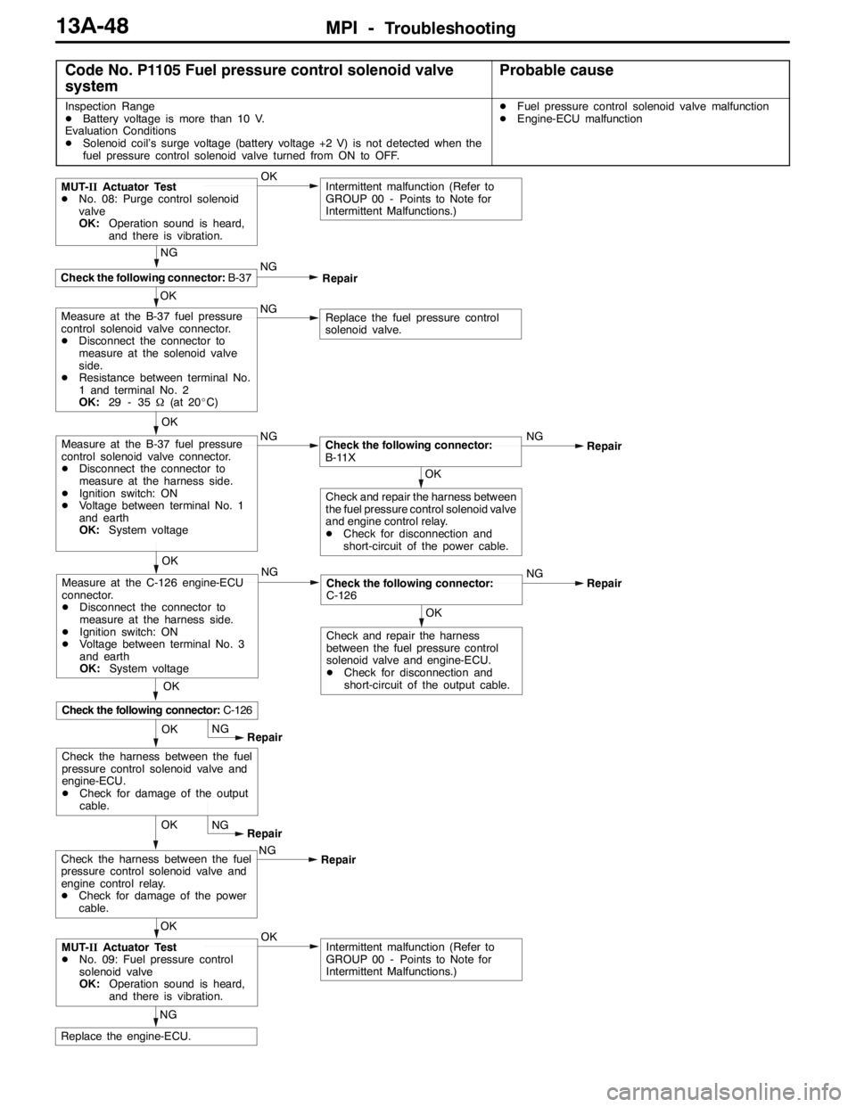
Code No. P1105 Fuel pressure control solenoid valve
systemProbable cause
Inspection Range
DBattery voltage is more than 10 V.
Evaluation Conditions
DSolenoid coil’s surge voltage (battery voltage +2 V) is not detected when the
fuel pressure control solenoid valve turned from ON to OFF.DFuel pressure control solenoid valve malfunction
DEngine-ECU malfunction
OK
NG
Replace the engine-ECU.
OKIntermittent malfunction (Refer to
GROUP 00 - Points to Note for
Intermittent Malfunctions.)MUT-IIActuator Test
DNo. 09: Fuel pressure control
solenoid valve
OK:Operation sound is heard,
and there is vibration.OKNG
Repair
OK
NG
Intermittent malfunction (Refer to
GROUP 00 - Points to Note for
Intermittent Malfunctions.)
OK
Check the following connector:B-37
MUT-IIActuator Test
DNo. 08: Purge control solenoid
valve
OK:Operation sound is heard,
and there is vibration.
NG
Repair
NGNG
Repair
OK
OK
Check and repair the harness
between the fuel pressure control
solenoid valve and engine-ECU.
DCheck for disconnection and
short-circuit of the output cable.
Check the following connector:
C-126
OK
Check the following connector:C-126
Measure at the C-126 engine-ECU
connector.
DDisconnect the connector to
measure at the harness side.
DIgnition switch: ON
DVoltage between terminal No. 3
and earth
OK:System voltageNG
Replace the fuel pressure control
solenoid valve.Measure at the B-37 fuel pressure
control solenoid valve connector.
DDisconnect the connector to
measure at the solenoid valve
side.
DResistance between terminal No.
1 and terminal No. 2
OK:29 - 35Ω(at 20_C)
OK
NG
Measure at the B-37 fuel pressure
control solenoid valve connector.
DDisconnect the connector to
measure at the harness side.
DIgnition switch: ON
DVoltage between terminal No. 1
and earth
OK:System voltage
OKNG
Repair
OK
OKCheck and repair the harness between
the fuel pressure control solenoid valve
and engine control relay.
DCheck for disconnection and
short-circuit of the power cable.
Check the following connector:
B-11X
NG
RepairCheck the harness between the fuel
pressure control solenoid valve and
engine control relay.
DCheck for damage of the power
cable.NG
Repair
OK
Check the harness between the fuel
pressure control solenoid valve and
engine-ECU.
DCheck for damage of the output
cable.
Page 581 of 1449

MPI -Troubleshooting13A-49
Code No. P1500 Alternator FR terminal systemProbable cause
Inspection Range
DEngine speed: More than 50 r/min
Evaluation Conditions
DThe input voltage from the alternator FR terminal is between 4.8 V and 5.2 V
or is the battery voltage for 20 seconds.DOpen circuit in the alternator FR terminal circuit
DMalfunction of engine-ECU
OK
Intermittent Malfunction
(Refer to GROUP 00 - Points to
Note for Intermittent Malfunction.)
OK
Check the trouble symptoms.NGReplace the engine-ECU.
OK
Intermittent Malfunction
(Refer to GROUP 00 - Points to
Note for Intermittent Malfunction.)
OK
Check the trouble symptoms.NGReplace the alternator. NG
OK
Check the harness between the middle
connector and engine-ECU.
DCheck for damage of the output
wire.Repair NG
OK
Check the harness between the
alternator and middle connector.
DCheck for damage of the output
wire.Repair
OK
Measure at the B-14 middle
connector.
DUsing the test harness
(MB991658), connect the
connector and measure at the
pickup harness.
DEngine: Idling (After warm-up)
DRadiator fan: OFF
DVoltage between terminal No. 5
and earth.
OK:The voltage drops when
the headlamp is turned
from OFF to ON.NGCheck the following connector:
B-22NG
Repair
OK
Replace the alternator.NG
OK
Check the harness between the
alternator and middle connector.
DCheck for short circuit of the
output wire.Repair
OK
Measure at the B-14 middle
connector.
DUsing the test harness
(MB991658), connect the
connector and measure at the
pickup harness.
DIgnition switch: ON
DVoltage between terminal No.5
and earth.
OK:5-6VNGCheck the following connector:
B-22NG
Repair
OK
Intermittent Malfunction
(Refer to GROUP 00 - Points to
Note for Intermittent Malfunction.)
OK
Check the trouble symptoms.NGReplace the engine-ECU. NG
OK
Check the harness between the
middle connector and engine-ECU.
DCheck for short circuit of the
output wire.Repair
OK
Measure at the B-14 middle
connector.
DDisconnect the connector to
measure at the female connector
side.
DIgnition switch: ON
DVoltage between terminal No.5
and earth.
OK:4.9 - 5.1 VNGCheck the following connector:
C-122NG
Repair
Check the following connector:
B-14NG
Repair
Page 582 of 1449

MPI -Troubleshooting13A-50
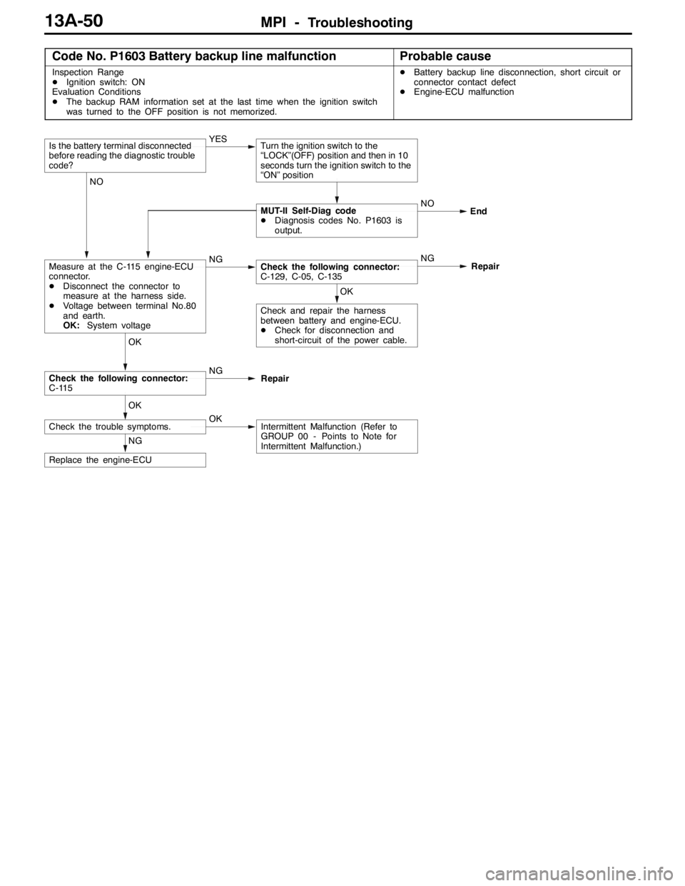
Code No. P1603 Battery backup line malfunctionProbable cause
Inspection Range
DIgnition switch: ON
Evaluation Conditions
DThe backup RAM information set at the last time when the ignition switch
was turned to the OFF position is not memorized.DBattery backup line disconnection, short circuit or
connector contact defect
DEngine-ECU malfunction
NG
Replace the engine-ECU
OK
Check the trouble symptoms.OKIntermittent Malfunction (Refer to
GROUP 00 - Points to Note for
Intermittent Malfunction.)
OK
Check the following connector:
C-115NG
Repair
OK
Check and repair the harness
between battery and engine-ECU.
DCheck for disconnection and
short-circuit of the power cable.
NGCheck the following connector:
C-129, C-05, C-135NG
Repair NO
MUT-II Self-Diag code
DDiagnosis codes No. P1603 is
output.End
NO
Measure at the C-115 engine-ECU
connector.
DDisconnect the connector to
measure at the harness side.
DVoltage between terminal No.80
and earth.
OK:System voltageYES
Turn the ignition switch to the
“LOCK”(OFF) position and then in 10
seconds turn the ignition switch to the
“ON” positionIs the battery terminal disconnected
before reading the diagnostic trouble
code?
Page 583 of 1449

MPI -Troubleshooting13A-51
Code No.P1610 Immobilizer system
Inspection Range
DIgnition switch: ON
Set Conditions
DImproper communication between the engine-ECU and the immobilizer-ECUDOpen or short circuit, or loose connector contact
DMalfunction of the immobilizer-ECU
DMalfunction of the engine-ECU
NOTE
(1) If the registered ignition keys are close each other when starting the engine, radio interference may
cause this code to be displayed.
(2) This code may be displayed when registering the key encrypted code.
NG
Replace the engine-ECU.
Check the trouble symptoms.
NG
Replace the immobilizer-ECU
OK
Check the trouble symptoms.
OK
Check the harness wire between the
immobilizer-ECU and the
engine-ECU, and repair if necessary.NG
Replace
Check the following connectors:
C-202, C-130, C-118NG
Repair
Page 584 of 1449

MPI -Troubleshooting13A-52
INSPECTION CHART FOR TROUBLE SYMPTOMS
Inspection
procedureCheck itemsReference page
1Communication between MUT-IIand entire system is not possible.13A-54
2Only communication between MUT-IIand engine-ECU is not possible.13A-55
3Engine warning lamp does not illuminate immediately after ignition switch is set to ON position.13A-56
4Engine warning lamp stays illuminated and does not turn OFF.13A-57
5Starting disabled (Starter does not rotate.)13A-58
6Starting disabled (Starter rotates but initial combustion does not occur.)13A-59
7Starting disabled (Initial combustion occurs but is incomplete.)13A-61
Improper starting (Starting time is long.)
8Unstable idling (Rough idling, hunting)13A-63
Inappropriate idling speed (High or low idling speed)
Engine stalls (Die out) during idling
9Engine stalls when starting travel. (Pass out)13A-66
10Engine stalls during deceleration13A-67
11Pulsation (Hesitation, sag)13A-68
Poor acceleration
Stumbling
Surging
12Shock during acceleration13A-70
13Shock during deceleration13A-71
14Knocking13A-72
15Deviation of ignition interval13A-73
16Run on (Dieseling)13A-74
17Abnormal odor, white smoke, black smoke, high CO or HC concentration when idling13A-75
18Battery dies13A-77
19Overheating13A-79
20Abnormal radiator fan motor rotation13A-80
21A/C ineffective13A-81
22Engine-ECU power supply, engine control relay, ignition switch-IG1 system13A-82
23Fuel pump system13A-85
24Radiator fan control relay system13A-87
25Condenser fan relay system13A-89
26A/C switch system13A-92
27A/C compressor relay system13A-93
28A/C load signal system13A-95
29Secondary air control solenoid valve system13A-96
30Intercooler water spray circuit system13A-97
31Intercooler water spray lamp system13A-99
32Ignition coil (integrated power transistor) system13A-100
Page 585 of 1449

MPI -Troubleshooting
Fig. 1
Vehicle
speedInitial ac-
celerator
pedal de-
pressionNormalHesitation
Sag
TimeFig. 2
Normal
Initial ac-
celerator
pedal de-
pression
IdlingStumble
Time Vehicle
speed
13A-53
PROBLEM SYMPTOMS TABLE (FOR YOUR INFORMATION)
ItemsSymptom
StartingWon’t startThe starter is used to crank the engine, but there is no combustion within the
cylinders, and the engine won’t start.
Fires up and diesThere is combustion within the cylinders, but then the engine soon stalls.
Hard startingEngine starts after cranking a while.
Idling
stability
HuntingEngine speed doesn’t remain constant; changes at idle.
stability
Rough idleUsually, a judgement can be based upon the movement of the tachometer
pointer, and the vibration transmitted to the steering wheel, shift lever, body, etc.
This is called rough idle.
Incorrect idle speedThe engine doesn’t idle at the usual correct speed.
Engine stall
(Die out)The engine stalls when the foot is taken from the accelerator pedal, regardless
of whether the vehicles is moving or not.
Engine stall
(Pass out)The engine stalls when the accelerator pedal is depressed or while it is being
used.
DrivingHesitation Sag“Hesitation” is the delay in response of the vehicle speed (engine speed) that
occurs when the accelerator is depressed in order to accelerate from the speed
at which the vehicle is now traveling, or a temporary drop in vehicle speed
(engine speed) during such acceleration.
Serious hesitation is called “sag”. (Refer to Fig. 1)
Poor accelerationPoor acceleration is inability to obtain an acceleration corresponding to the
degree of throttle opening, even though acceleration is smooth, or the inability
to reach maximum speed.
StumbleEngine speed increase is delayed when the accelerator pedal is initially
depressed for acceleration. (Refer to Fig. 2)
ShockThe feeling of a comparatively large impact or vibration when the engine is
accelerated or decelerated.
SurgeThis is repeated surging ahead during constant speed travel or during variable
speed travel.
KnockingA sharp sound like a hammer striking the cylinder walls during driving and which
adversely affects driving.
StoppingRun on
(“Dieseling”)The condition in which the engine continues to run after the ignition switch is
turned to “LOCK” (OFF) position. Also called “Dieseling”.
Page 587 of 1449

MPI -Troubleshooting13A-55
Inspection Procedure 2
Only communication between MUT-IIand engine-ECU is
not possible.
Probable cause
Causes shown on right are suspected.DIgnition switch malfunction
DEngine control relay malfunction
DEngine-ECU malfunction
NG
Replace the engine-ECU.
OK
Check the trouble symptoms.OKIntermittent malfunction
(Refer to GROUP 00 - Points to Note
for Intermittent Malfunctions.)
OK
Check the harness between the
diagnosis connector and engine-ECU.
DCheck for disconnection,
short-circuit and damage of the
communication cable.
DCheck for disconnection,
short-circuit and damage of the
signal cable.NG
Repair
OK
Check the following connectors:
C-26, C-130, C-118, C-108, C-28
Repair
Check the engine warning lamp.
DIgnition switch: ON
OK:Engine warning lamp is
illuminated.NGCheck the Inspection Procedure 22:
Engine-ECU power supply, engine
control relay, ignition switch-IG system.
NOTE
If the problem symptom does not disappear in the vehicle with MMCS after carrying out the above - mentioned
inspection procedure, there may be a malfunction in the multi - center display.
Page 588 of 1449

MPI -Troubleshooting13A-56
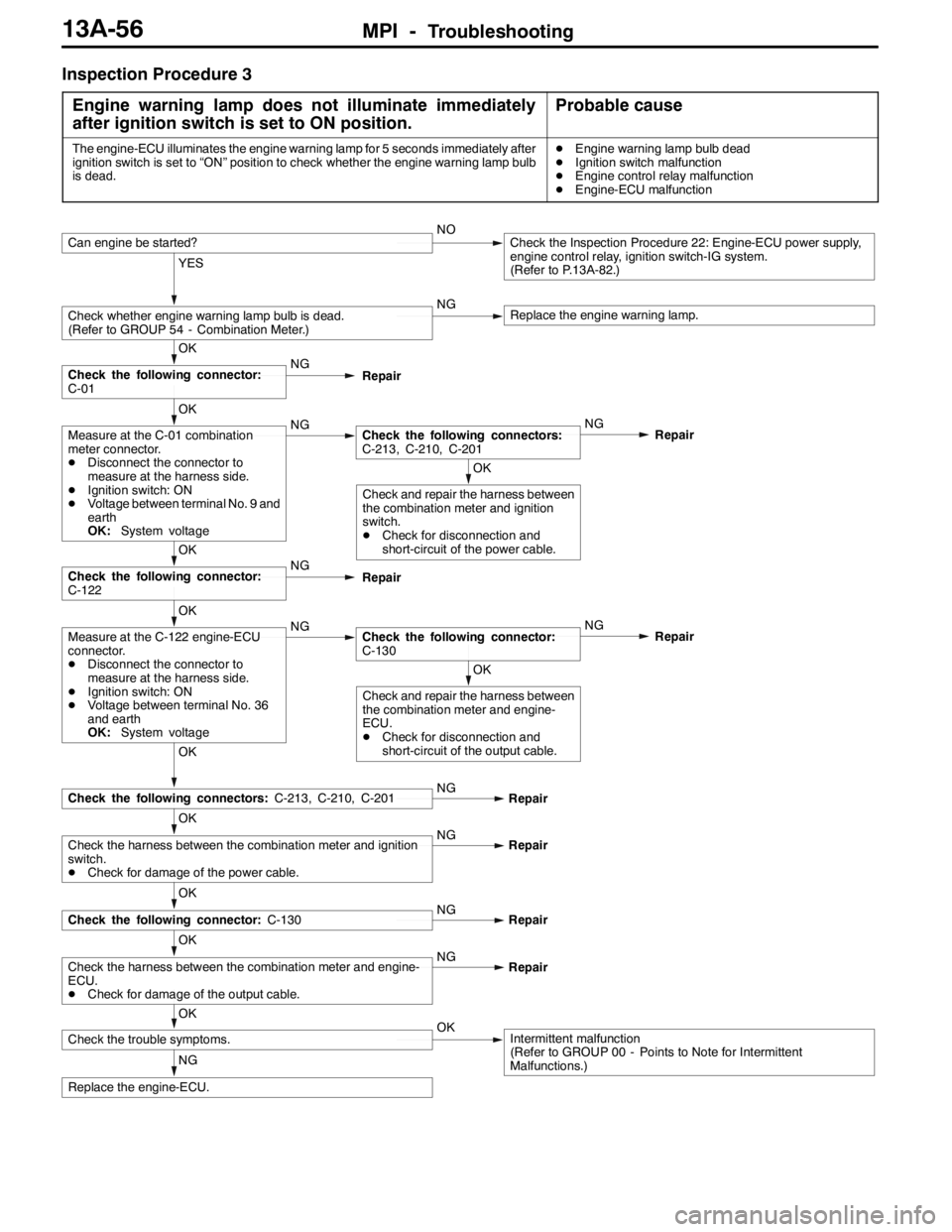
Inspection Procedure 3
Engine warning lamp does not illuminate immediately
after ignition switch is set to ON position.
Probable cause
The engine-ECU illuminates the engine warning lamp for 5 seconds immediately after
ignition switch is set to “ON” position to check whether the engine warning lamp bulb
is dead.DEngine warning lamp bulb dead
DIgnition switch malfunction
DEngine control relay malfunction
DEngine-ECU malfunction
NG
Replace the engine-ECU.
OK
Check the trouble symptoms.OKIntermittent malfunction
(Refer to GROUP 00 - Points to Note for Intermittent
Malfunctions.)
OK
Check the harness between the combination meter and engine-
ECU.
DCheck for damage of the output cable.NG
Repair
OK
Check the following connector:C-130NG
Repair
OK
Check the harness between the combination meter and ignition
switch.
DCheck for damage of the power cable.NG
Repair
OK
Check the following connectors:C-213, C-210, C-201NG
Repair
OK
Check and repair the harness between
the combination meter and engine-
ECU.
DCheck for disconnection and
short-circuit of the output cable.
OK
Measure at the C-122 engine-ECU
connector.
DDisconnect the connector to
measure at the harness side.
DIgnition switch: ON
DVoltage between terminal No. 36
and earth
OK:System voltageNGCheck the following connector:
C-130NG
Repair
OK
Check the following connector:
C-122NG
Repair
OK
Check and repair the harness between
the combination meter and ignition
switch.
DCheck for disconnection and
short-circuit of the power cable.
OK
Measure at the C-01 combination
meter connector.
DDisconnect the connector to
measure at the harness side.
DIgnition switch: ON
DVoltage between terminal No. 9 and
earth
OK:System voltageNGCheck the following connectors:
C-213, C-210, C-201NG
Repair
OK
Check the following connector:
C-01NG
Repair
YES
Check whether engine warning lamp bulb is dead.
(Refer to GROUP 54 - Combination Meter.)NGReplace the engine warning lamp.
Can engine be started?NOCheck the Inspection Procedure 22: Engine-ECU power supply,
engine control relay, ignition switch-IG system.
(Refer to P.13A-82.)