Page 606 of 1449
MPI -Troubleshooting13A-74
Inspection Procedure 16
Run on (Dieseling)
Probable cause
Causes shown on right are suspected.DInjector malfunction
DEngine-ECU malfunction
NG
Replace the engine-ECU.
Check the trouble symptoms.OK
End
Replace the injectors for all cylinders.
Page 607 of 1449

MPI -Troubleshooting13A-75
Inspection Procedure 17
Abnormal odor, white smoke, black smoke, high CO or HC
concentration when idling
Probable cause
Causes shown on right are suspected.DAir/fuel ratio control system malfunction
DIgnition system malfunction
DFuel system malfunction
DIntake and exhaust system malfunction
DExhaust gas purifier system malfunction
DImproper compression pressure
DCatalyst defect
DEngine-ECU malfunction
OK
To the next page
OK
Check the fuel pressure. (Refer to P.13A-128.)
OK
MUT-IIData list
DNo. 59: Oxygen sensor (rear)
(Refer to P.13A-105.)NGCheck the Code No. P0136: Oxygen sensor (rear) system.
(Refer to P.13A-27.)
OK
MUT-IIData list
DNo. 11: Oxygen sensor (front) (Refer to P.13A-102.)NGCheck the Code No. P0130: Oxygen sensor (front) system.
(Refer to P.13A-24.)
OK
Check for exhaust gas leaks from exhaust manifold.NG
Repair
OK
Check the air intake from the intake hose and intake manifold.NG
Repair
OK
MUT-IIData list
DNo. 12: Air flow sensor
DNo. 13: Intake air temperature sensor
DNo. 21: Engien coolant temperature sensor
DNo. 25: Barometric pressure sensor
(Refer to P.13A-102.)
Proceed to OK if all service data values are correct.
Proceed to NG if there is even one abnormal service data value.NGRefer to inspections for diagnosis code of sensor showing
abnormal service data. (Refer to P.13A-102.)
OK
Check the ignition timing.
(Refer to GROUP 11 - Engine Adjustment.)NGCheck the Inspection Procedure 15: Deviation of ignition interval
(Refer to P.13A-73.)
NO
MUT-IIActuator test
DNo. 01: No. 1 injector
DNo. 02: No. 2 injector
DNo. 03: No. 3 injector
DNo. 04: No. 4 injector
OK:The idling state changes.
DProceed to NG if the cylinder (NG cylinder) for which the idling
state did not change when injector was stopped is pinpointed.
DProceed to OK if all cylinders are OK, or if the NG cylinder
cannot be pinpointed.NGCheck the Code No. P0201: No. 1 injector system, P0202: No. 2
injector system, P0203: No. 3 injector system and P0204: No. 4
injector system. (Refer to P.13A-30, 31, 32, 33.)
MUT-IISelf-Diag code
DIs a diagnosis code output?YESINSPECTION CHART FOR DIAGNOSIS CODE
(Refer to P.13A-12.)
Page 608 of 1449

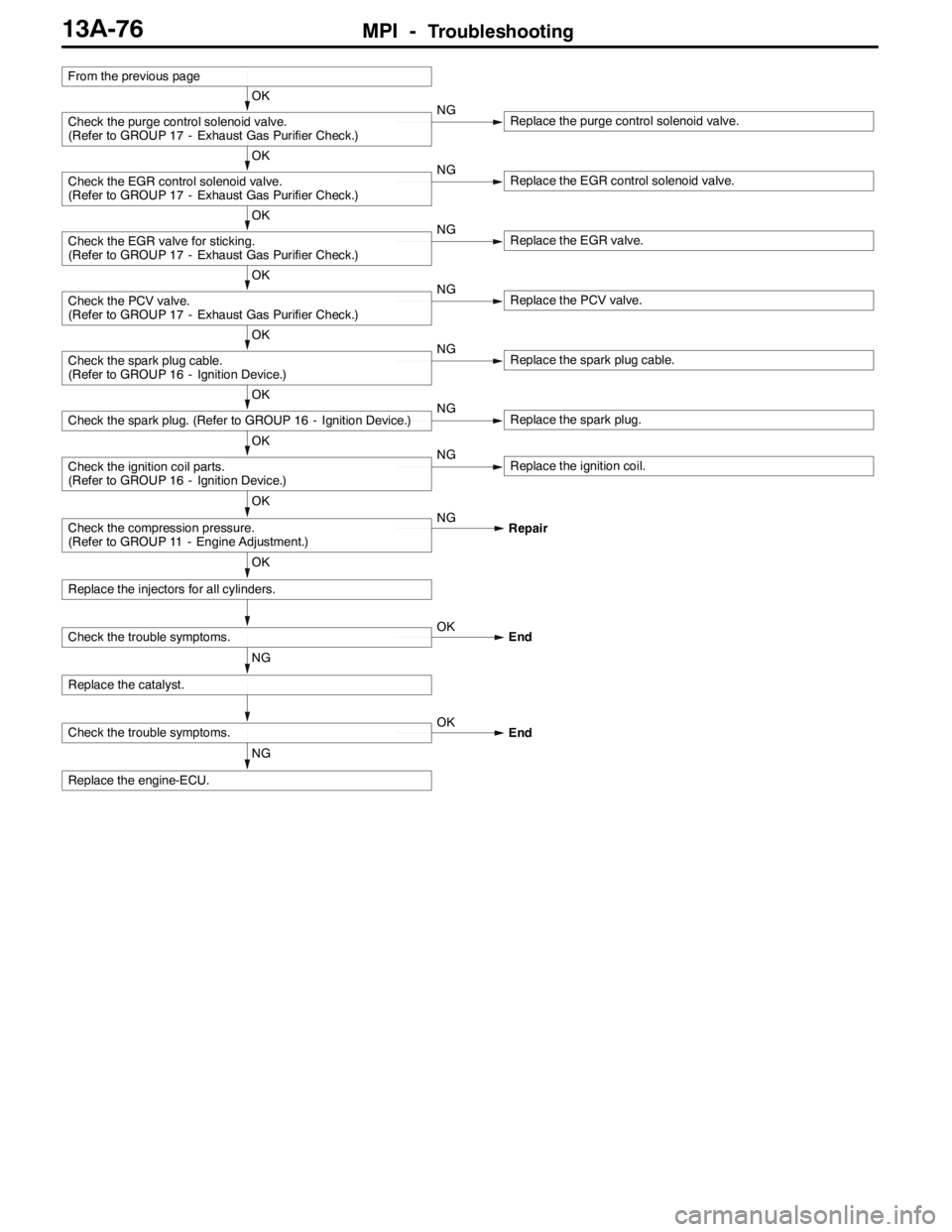
MPI -Troubleshooting13A-76
NG
Replace the engine-ECU.
Check the trouble symptoms.OK
End
NG
Replace the catalyst.
Check the trouble symptoms.OK
End
OK
Replace the injectors for all cylinders.
OK
Check the compression pressure.
(Refer to GROUP 11 - Engine Adjustment.)NG
Repair
OK
Check the ignition coil parts.
(Refer to GROUP 16 - Ignition Device.)NGReplace the ignition coil.
OK
Check the spark plug. (Refer to GROUP 16 - Ignition Device.)NGReplace the spark plug.
OK
Check the spark plug cable.
(Refer to GROUP 16 - Ignition Device.)NGReplace the spark plug cable.
OK
Check the PCV valve.
(Refer to GROUP 17 - Exhaust Gas Purifier Check.)NGReplace the PCV valve.
OK
Check the EGR valve for sticking.
(Refer to GROUP 17 - Exhaust Gas Purifier Check.)NGReplace the EGR valve.
OK
Check the EGR control solenoid valve.
(Refer to GROUP 17 - Exhaust Gas Purifier Check.)NGReplace the EGR control solenoid valve.
OK
Check the purge control solenoid valve.
(Refer to GROUP 17 - Exhaust Gas Purifier Check.)NGReplace the purge control solenoid valve.
From the previous page
Page 609 of 1449

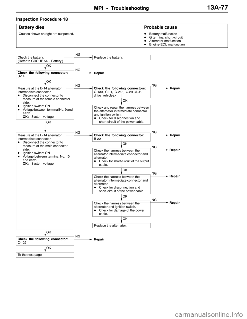
MPI -Troubleshooting13A-77
Inspection Procedure 18
Battery dies
Probable cause
Causes shown on right are suspected.DBattery malfunction
DG terminal short - circuit
DAlternator malfunction
DEngine-ECU malfunction
OK
To the next page
OK
Check the following connector:
C-122NG
Repair
OK
Replace the alternator.NG
OK
Check the harness between the
alternator and ignition switch.
DCheck for damage of the power
cable.Repair NG
OK
Check the harness between the
alternator intermediate connector and
alternator.
DCheck for disconnection and
short-circuit of the power cable.Repair NG
OK
Check the harness between the
alternator intermediate connector and
alternator.
DCheck for short-circuit of the output
cable.Repair
OK
Measure at the B-14 alternator
intermediate connector.
DDisconnect the connector to
measure at the male connector
side.
DIgnition switch: ON
DVoltage between terminal No. 10
and earth
OK:System voltageNGCheck the following connector:
B-22NG
Repair
OK
Check and repair the harness between
the alternator intermediate connector
and ignition switch.
DCheck for disconnection and
short-circuit of the power cable.
OK
Measure at the B-14 alternator
intermediate connector.
DDisconnect the connector to
measure at the female connector
side.
DIgnition switch: ON
DVoltage between terminal No. 9 and
earth
OK:System voltageNGCheck the following connectors:
C-130, C-01, C-213, C-29
drive vehicles>NG
Repair
OK
Check the following connector:
B-14NG
Repair
Check the battery.
(Refer to GROUP 54 - Battery.)NGReplace the battery.
Page 610 of 1449
MPI -Troubleshooting13A-78
NG
Replace the engine-ECU.
OK
Check the trouble symptoms.OKIntermittent malfunction
(Refer to GROUP 00 - Points to Note
for Intermittent Malfunctions.)
OK
Measure at the C-122 engine-ECU
connector.
DMeasure the engine-ECU terminal
voltage.
DEngine: Idling (after warm-up)
DRadiator fan: Stopped
DVoltage between terminal No. 33
and earth
OK:Voltage rises 0.2 to 3.5 V
when headlamp is turned
OFF and ON.NGCheck the charging device.
(Refer to GROUP 16 - Charging
Device.)
OK
Measure at the C-122 engine-ECU
connector.
DDisconnect the connector to
measure at the harness side.
DIgnition switch: ON
DVoltage between terminal No. 33
and earth
OK:System voltageNGCheck and repair the harness between
the alternator intermediate connector
and engine-ECU.
DCheck for short-circuit of output
cable.
From the previous page
Page 611 of 1449

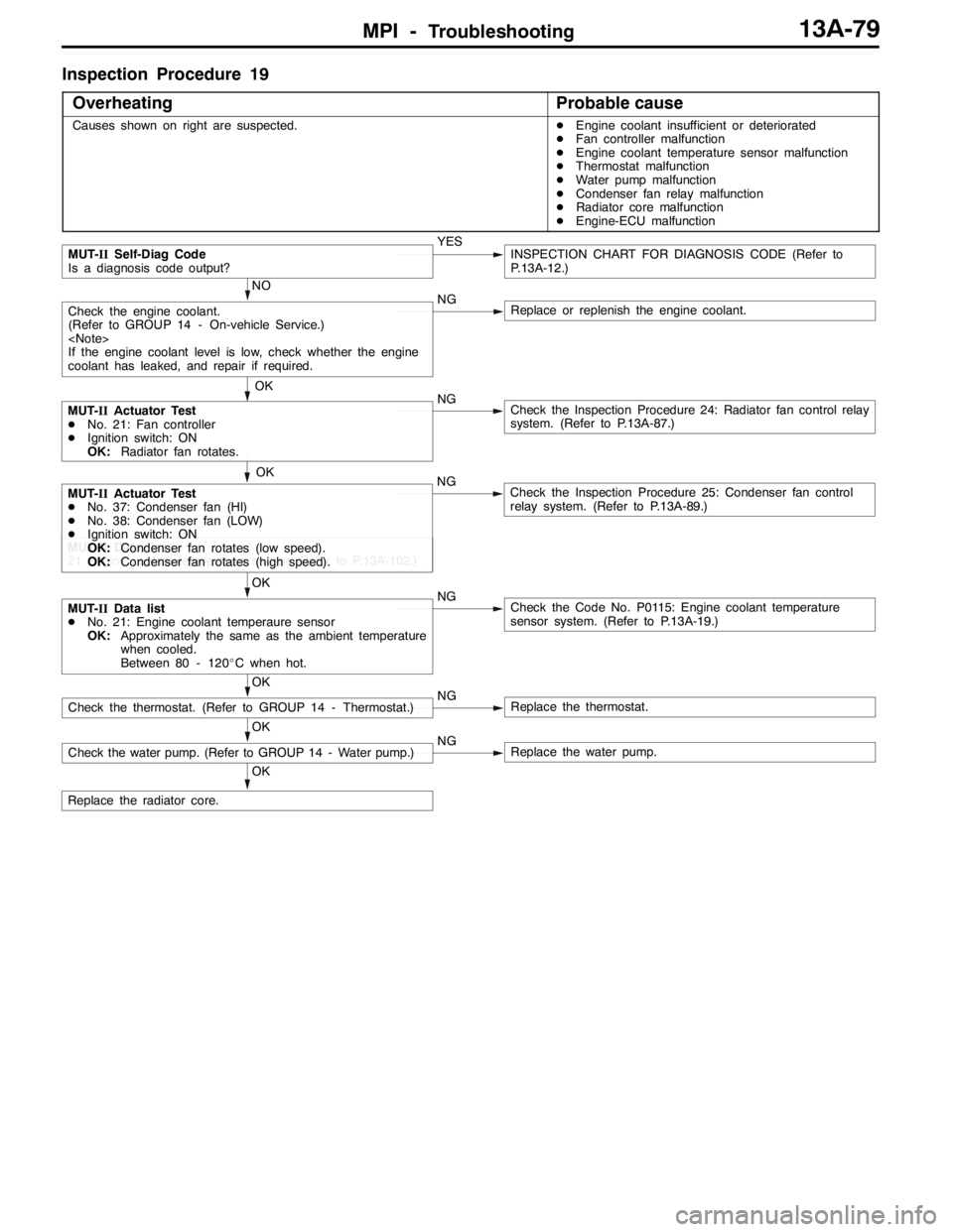
MPI -Troubleshooting13A-79
Inspection Procedure 19
Overheating
Probable cause
Causes shown on right are suspected.DEngine coolant insufficient or deteriorated
DFan controller malfunction
DEngine coolant temperature sensor malfunction
DThermostat malfunction
DWater pump malfunction
DCondenser fan relay malfunction
DRadiator core malfunction
DEngine-ECU malfunction
NO
NG
Replace or replenish the engine coolant.
OK
Replace the radiator core.
OK
Check the water pump. (Refer to GROUP 14 - Water pump.)NGReplace the water pump.
OK
Check the thermostat. (Refer to GROUP 14 - Thermostat.)NGReplace the thermostat.
OK
MUT-IIData list
DNo. 21: Engine coolant temperaure sensor
OK:Approximately the same as the ambient temperature
when cooled.
Between 80 - 120_C when hot.NGCheck the Code No. P0115: Engine coolant temperature
sensor system. (Refer to P.13A-19.)
MUT-IIData list
21 Engine coolant temperature sensor (Refer to P.13A-102.)
OK
MUT-IIActuator Test
DNo. 37: Condenser fan (HI)
DNo. 38: Condenser fan (LOW)
DIgnition switch: ON
OK:Condenser fan rotates (low speed).
OK:Condenser fan rotates (high speed).NGCheck the Inspection Procedure 25: Condenser fan control
relay system. (Refer to P.13A-89.)
MUT-IIActuator Test
DNo. 21: Fan controller
DIgnition switch: ON
OK:Radiator fan rotates.NGCheck the Inspection Procedure 24: Radiator fan control relay
system. (Refer to P.13A-87.)
OK
Check the engine coolant.
(Refer to GROUP 14 - On-vehicle Service.)
If the engine coolant level is low, check whether the engine
coolant has leaked, and repair if required.
MUT-IISelf-Diag Code
Is a diagnosis code output?YESINSPECTION CHART FOR DIAGNOSIS CODE (Refer to
P.13A-12.)
Page 612 of 1449
MPI -Troubleshooting13A-80
Inspection Procedure 20
Abnormal radiator fan motor rotation
Probable cause
Causes shown on right are suspected.DFan controller malfunction
DEngine-ECU malfunction
Intermittent malfunction (Refer to
GROUP 00 - Points to Note for
Intermittent Malfunctions.)OK
Replace the engine-ECU.
OK
Check the radiator fan motor drive.
DDisconnect the C-126
engine-ECU connector.
DShort-circuit terminal No. 21 with
the earth.
DIgnition switch: ON
OK:Radiator fan motor stops.NGCheck the trouble symptoms.
Check the following connector:
C-126NG
Repair
OK
NG
Measure at the C-126 engine-ECU connector.
DDisconnect the connector to measure at the harness side.
DIgnition switch: ON
DVoltage between terminal No. 21 and earth
OK:4.9 - 5.1VReplace the fan controller. NG
OK
NG
Repair
NGRepair
Replace the fan controller.
Check the following connectors:A-13, A-21
Check the harness between the fan controller and engine-ECU.
DCheck for disconnection of the output cable.OK
OK
Page 613 of 1449

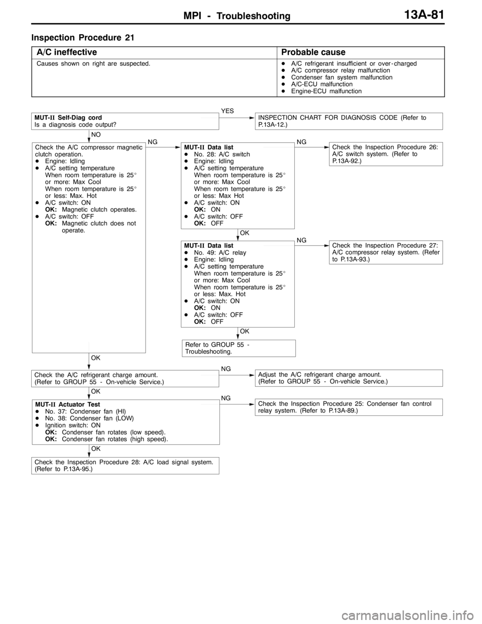
MPI -Troubleshooting13A-81
Inspection Procedure 21
A/C ineffective
Probable cause
Causes shown on right are suspected.DA/C refrigerant insufficient or over - charged
DA/C compressor relay malfunction
DCondenser fan system malfunction
DA/C-ECU malfunction
DEngine-ECU malfunction
NGCheck the Inspection Procedure 25: Condenser fan control
relay system. (Refer to P.13A-89.)
NGAdjust the A/C refrigerant charge amount.
(Refer to GROUP 55 - On-vehicle Service.)
MUT-IISelf-Diag cord
Is a diagnosis code output?YESINSPECTION CHART FOR DIAGNOSIS CODE (Refer to
P.13A-12.)
Refer to GROUP 55 -
Troubleshooting.
OK
OK
Check the A/C compressor magnetic
clutch operation.
DEngine: Idling
DA/C setting temperature
When room temperature is 25_
or more: Max Cool
When room temperature is 25_
or less: Max. Hot
DA/C switch: ON
OK:Magnetic clutch operates.
DA/C switch: OFF
OK:Magnetic clutch does not
operate.NGMUT-IIData list
DNo. 28: A/C switch
DEngine: Idling
DA/C setting temperature
When room temperature is 25_
or more: Max Cool
When room temperature is 25_
or less: Max Hot
DA/C switch: ON
OK:ON
DA/C switch: OFF
OK:OFFNGCheck the Inspection Procedure 26:
A/C switch system. (Refer to
P.13A-92.)
NO
OK
MUT-IIData list
DNo. 49: A/C relay
DEngine: Idling
DA/C setting temperature
When room temperature is 25_
or more: Max Cool
When room temperature is 25_
or less: Max. Hot
DA/C switch: ON
OK:ON
DA/C switch: OFF
OK:OFFNGCheck the Inspection Procedure 27:
A/C compressor relay system. (Refer
to P.13A-93.)
Check the A/C refrigerant charge amount.
(Refer to GROUP 55 - On-vehicle Service.)
OK
OK
Check the Inspection Procedure 28: A/C load signal system.
(Refer to P.13A-95.)
MUT-IIActuator Test
DNo. 37: Condenser fan (HI)
DNo. 38: Condenser fan (LOW)
DIgnition switch: ON
OK:Condenser fan rotates (low speed).
OK:Condenser fan rotates (high speed).